EP0446370B1 - Non-contact profile control apparatus - Google Patents
Non-contact profile control apparatus Download PDFInfo
- Publication number
- EP0446370B1 EP0446370B1 EP90913890A EP90913890A EP0446370B1 EP 0446370 B1 EP0446370 B1 EP 0446370B1 EP 90913890 A EP90913890 A EP 90913890A EP 90913890 A EP90913890 A EP 90913890A EP 0446370 B1 EP0446370 B1 EP 0446370B1
- Authority
- EP
- European Patent Office
- Prior art keywords
- contact
- tracing
- model
- contact distance
- normal direction
- Prior art date
- Legal status (The legal status is an assumption and is not a legal conclusion. Google has not performed a legal analysis and makes no representation as to the accuracy of the status listed.)
- Expired - Lifetime
Links
Images


Classifications
-
- B—PERFORMING OPERATIONS; TRANSPORTING
- B23—MACHINE TOOLS; METAL-WORKING NOT OTHERWISE PROVIDED FOR
- B23Q—DETAILS, COMPONENTS, OR ACCESSORIES FOR MACHINE TOOLS, e.g. ARRANGEMENTS FOR COPYING OR CONTROLLING; MACHINE TOOLS IN GENERAL CHARACTERISED BY THE CONSTRUCTION OF PARTICULAR DETAILS OR COMPONENTS; COMBINATIONS OR ASSOCIATIONS OF METAL-WORKING MACHINES, NOT DIRECTED TO A PARTICULAR RESULT
- B23Q35/00—Control systems or devices for copying directly from a pattern or a master model; Devices for use in copying manually
- B23Q35/04—Control systems or devices for copying directly from a pattern or a master model; Devices for use in copying manually using a feeler or the like travelling along the outline of the pattern, model or drawing; Feelers, patterns, or models therefor
- B23Q35/08—Means for transforming movement of the feeler or the like into feed movement of tool or work
- B23Q35/12—Means for transforming movement of the feeler or the like into feed movement of tool or work involving electrical means
- B23Q35/127—Means for transforming movement of the feeler or the like into feed movement of tool or work involving electrical means using non-mechanical sensing
-
- G—PHYSICS
- G05—CONTROLLING; REGULATING
- G05B—CONTROL OR REGULATING SYSTEMS IN GENERAL; FUNCTIONAL ELEMENTS OF SUCH SYSTEMS; MONITORING OR TESTING ARRANGEMENTS FOR SUCH SYSTEMS OR ELEMENTS
- G05B19/00—Programme-control systems
- G05B19/02—Programme-control systems electric
- G05B19/42—Recording and playback systems, i.e. in which the programme is recorded from a cycle of operations, e.g. the cycle of operations being manually controlled, after which this record is played back on the same machine
- G05B19/4202—Recording and playback systems, i.e. in which the programme is recorded from a cycle of operations, e.g. the cycle of operations being manually controlled, after which this record is played back on the same machine preparation of the programme medium using a drawing, a model
- G05B19/4207—Recording and playback systems, i.e. in which the programme is recorded from a cycle of operations, e.g. the cycle of operations being manually controlled, after which this record is played back on the same machine preparation of the programme medium using a drawing, a model in which a model is traced or scanned and corresponding data recorded
-
- G—PHYSICS
- G05—CONTROLLING; REGULATING
- G05B—CONTROL OR REGULATING SYSTEMS IN GENERAL; FUNCTIONAL ELEMENTS OF SUCH SYSTEMS; MONITORING OR TESTING ARRANGEMENTS FOR SUCH SYSTEMS OR ELEMENTS
- G05B2219/00—Program-control systems
- G05B2219/30—Nc systems
- G05B2219/37—Measurements
- G05B2219/37425—Distance, range
-
- G—PHYSICS
- G05—CONTROLLING; REGULATING
- G05B—CONTROL OR REGULATING SYSTEMS IN GENERAL; FUNCTIONAL ELEMENTS OF SUCH SYSTEMS; MONITORING OR TESTING ARRANGEMENTS FOR SUCH SYSTEMS OR ELEMENTS
- G05B2219/00—Program-control systems
- G05B2219/30—Nc systems
- G05B2219/50—Machine tool, machine tool null till machine tool work handling
- G05B2219/50356—Tool perpendicular, normal to 3-D surface
Definitions
- the present invention relates to a noncontact tracing control system, and more particularly, to a noncontact tracing control system using distance detectors having a high measuring accuracy.
- a noncontact tracing control system using a noncontact distance detector as a tracer head has been developed, and, for example, an optical distance detector is used for this noncontact distance detector, and a model is traced by using this detector to detect the distance to the model surface.
- This system eliminates fears of damage to the model, and therefore, a soft material can be used for a model, which will enable a wider applicability thereof for machining and digitizing.
- the conventional noncontact tracing control system has a problem in that the tracing accuracy is lowered at portions of a model where an inclination thereof is large. Namely, at this portion, an optical measuring axis of a distance detector is not at a right angle to the model surface, and accordingly, the spot of light on the model surface is distorted into the shape of an ellipse, and thus the resolution of the distance detector is lowered and the tracing accuracy becomes low. Particularly, for a trigonometrical distance detector, a measurement sometimes becomes impossible because the optical measuring axis interferes with the model surface due to the angle thereof.
- EP-A-0436735 tracing accuracy is improved by acquiring a normal vector of a model surface based on measured values of a sampling taken at this time and at the previous time by two non-contact distance detectors of a tracer head, and by controlling the rotation of the tracer head in the direction of the projection of this normal vector when projected on a predetermined plane, to thereby carry out a distance measuring with a high accuracy.
- the optical measuring axis of the non-contact distance detector cannot be made to conform perfectly to the normal direction, depending on an inclination of the model surface, and thus in some cases, the measuring accuracy cannot be improved as much as expected.
- EP-A-0313801 discloses a machine for defining the surface of three-dimensional models in which a tracing head is moved over the surface of the model and maintained at right angles to the model surface.
- the present invention has been made in view of the aforesaid drawbacks, and an object of the present invention is to provide a non-contact tracing control system having an improved tracing accuracy by obtaining measured values with a higher accuracy from non-contact distance detectors.
- a non-contact tracing control system for machining or digitising a workpiece through tracing the shape of a model without contact therewith, the system comprising: a tracing head having first and second non-contact distance detectors for measuring the distance to a model surface without contact therewith; sampling means for sampling measured values of each of the first and second non-contact distance detectors at predetermined sampling times; storing means for storing a first measured value of the first non-contact distance detector and a second measured value of the second non-contact distance detector at the previous sampling; and, normal direction calculating means for obtaining a normal direction of the model surface; characterised by: the normal direction calculating means using at least three of the first measured value, the second measured value, a third measured value of the first non-contact distance detector, and a fourth measured value of the second non-contact distance detector of the present sampling, the normal direction calculating means calculating the normal direction by obtaining coordinate values of three points on the model surface using the three measured values, by obtaining first and second
- a coordinate value of each vertex of a micro quadrangle on the model surface is obtained from the measured values at the sampling of the previous time and the present time from two non-contact distance detectors, and a normal direction is acquired using three necessary vertex coordinate values thereof to control the rotation of two axes of the tracer head in this direction. Accordingly, the optical measuring axis of the non-contact distance detector is always at a right angle to the model surface, and thus a distance measuring with a high accuracy can be obtained.
- FIG. 1 is a block diagram showing a noncontact tracing control system and the peripheral constitution thereof according to the present invention.
- a processor 11 reads a system program stored in a ROM 12, through a bus 10, and controls the overall operation of a tracing control system 1 according to this system program.
- a RAM 13 is used as a data temporary storing device and stores measured values from distance detectors, which will be described later, and other temporary data.
- a nonvolatile memory 14 is constituted by a CMOS backed up by a battery, and stores various parameters such as a tracing direction and tracing speed, etc. input from a control panel 2 through an interface 15.
- a tracer head 4 of a tracing machine 3 is constituted by distance detectors 5a and 5b.
- a reflected light amount type distance detector using a semiconductor laser or a light emitting diode as a light source is used for the distance detectors 5a and 5b, each of which measures a distance to a model 6 without a contact therewith.
- Measured values La and Lb of these distance detectors are digital converted by A/D converters 16a and 16b in the tracing control system 1, and sequentially read by the processor 11.
- the processor 11 calculates displacement amounts of each axis based on the measured values La and Lb and signals from current position registers 19x, 19y, and 19z and generates speed commands Vx, Vy, and Vz of the respective axes based on these amounts of displacement, and commanded tracing direction and tracing speed, according to the known process.
- These speed commands are analog converted by D/A converters 17x, 17y, and 17z and input to servo amplifiers 18x, 18y, and 18z.
- the servo amplifiers 18x and 18y drive servomotors 32x and 32y of the tracing machine 3 based on these speed commands, to thereby move a table 31 in the X-axis direction and the Y-axis direction at right angles to the sheet surface.
- the servo amplifier 18z drives the servomotor 32z, and a column 7 is moved in the Z-axis direction to maintain a constant distance between the distance detector 5a and the model 6, as mentioned later.
- Pulse coders 33x, 33y, and 33z are provided in these servomotors 32x, 32y, and 32z for generating pulses FPx, FPy, and FPz at a predetermined amount of rotation of these servomotors.
- the current position registers 19x, 19y, and 19z store current position data Xa, Ya, and Za in each axial direction by counting up/down the detection pulses FPx, FPy, and FPz according to the respective rotation direction, and input the data to the processor 11.
- the processor 11 samples the measured values La and Lb of the distance detectors 5a and 5b at predetermined sampling times, while simultaneously controlling the above axes, acquires a normal vector on the model 6 using this sampling data, and generates a rotation command ⁇ c in the direction of an angle of a projection of the normal vector on the X-Y plane and a rotation command ⁇ b in the direction of an angle of the normal vector against the X-Y plane.
- the rotation commands ⁇ c and ⁇ b are analog converted by D/A converters 17c and 17b, respectively, and input to servo amplifiers 18c and 18b.
- the servo amplifier 18c drives a servomotor 32c and the servo amplifier 18b drives a servomotor 32b.
- the tracer head 4 is rotated in the B1 axis direction, with the rotation center of a measured point P1 being at a measuring axis 51, a predetermined distance from the distance detector 5a, through a drive mechanism 36 constituted by a pinion gear and an arc-shaped rack gear. Also, when the servomotor 32c is driven to rotate in the C1 axis direction, with the measuring axis 51 of the distance detector 5a as the center, by the drive mechanism 36, the distance detector 5b is rotated by the same angle of the circumference of a predetermined radius.
- a point P1 (intersection of the centers of the C1 and the B1 axes) is controlled to be constantly positioned on the surface of the model 6, by the above-mentioned Z-axis control, and at the same time, the table 31 is moved in the commanded tracing direction at the commanded speed to enable a workpiece 35 to be machined to the same shape as that of the model 6, by a cutter 34 attached to the column 7.
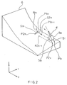
- the tracing is carried out by moving the tracer head 4 in the X-axis direction relative to the model 6 and at a predetermined speed, the measured values of the distance detectors 5a and 5b are sampled at predetermined times, and coordinate values of points P11, ... P1 n-1 , P1 n , and P21, ... P2 n-1 , P2 n on the model 6 are obtained based on these measured values and the current position data output from the current position registers.
- a surface vector S1n [X2 n - X1 n , Y2 n - Y1 n , Z2 n - Z1 n ] is obtained from the coordinate value of the point P1 n (X1 n , Y1 n , Z1 n ) and the coordinate value of the point P2 n (X2 n , Y2 n , Z2 n ), and a surface vector S2n [X1 n-1 - X1 n , Y1 n-1 - Y1 n , Z1 n-1 - Z1 n ] is obtained from the coordinate value of the point P1 n (X1 n , Y1 n , Z1 n ) and the coordinate value of the point P1 n-1 (X1 n-1 , Y1 n-1 , Z1 n-1 ).
- the measuring axes of the distance detectors 5a and 5b are always at a right angle to the surface of the model 6, and thus a distance measuring having a high accuracy is obtained.
- Figure 4 is a flow chart of a calculation processing of the rotation commands in an embodiment according to the present invention.
- the numerical values following the letter S show step numbers.
- the normal vector was obtained based on the measured value of one of the distance detectors at the previous sampling and the measured values of both of the distance detectors at the present sampling in the above embodiment, but this is not limited thereto in that the normal direction can be also obtained from at least three points by other combinations of the four measured values obtained by sampling at the present time and at the previous time.
- an optical trigonometrical type, eddy-current type, or ultrasonic type distance detector can be used as the distance detector.
- the whole shape of a model can be reproduced as numerical data by obtaining successive points on the model, and thus a tracing control system using a noncontact sensor has a greater effect when applied to a digitizing system.
- a normal direction on a model surface is obtained based on measured values from two noncontact distance detectors at the previous sampling and the present sampling and the rotation of a tracer head is controlled in this direction, and therefore, the measuring axes of the noncontact distance detectors are always at a right angle to the model surface, which enables a distance measuring with a high accuracy and improves tracing accuracy. Also, as no blind spot is generated due to interference with the model surface, a complicated three-dimensional model can be traced.
Abstract
Description
- The present invention relates to a noncontact tracing control system, and more particularly, to a noncontact tracing control system using distance detectors having a high measuring accuracy.
- Recently, a noncontact tracing control system using a noncontact distance detector as a tracer head has been developed, and, for example, an optical distance detector is used for this noncontact distance detector, and a model is traced by using this detector to detect the distance to the model surface. This system eliminates fears of damage to the model, and therefore, a soft material can be used for a model, which will enable a wider applicability thereof for machining and digitizing.
- The conventional noncontact tracing control system, however, has a problem in that the tracing accuracy is lowered at portions of a model where an inclination thereof is large. Namely, at this portion, an optical measuring axis of a distance detector is not at a right angle to the model surface, and accordingly, the spot of light on the model surface is distorted into the shape of an ellipse, and thus the resolution of the distance detector is lowered and the tracing accuracy becomes low. Particularly, for a trigonometrical distance detector, a measurement sometimes becomes impossible because the optical measuring axis interferes with the model surface due to the angle thereof.
- To solve this problem, the applicant filed a Japanese patent application no. 1-194500, entitled "NON-CONTACT TRACING CONTROL SYSTEM", on July 27, 1989, corresponding to EP-A-0436735. In EP-A-0436735, tracing accuracy is improved by acquiring a normal vector of a model surface based on measured values of a sampling taken at this time and at the previous time by two non-contact distance detectors of a tracer head, and by controlling the rotation of the tracer head in the direction of the projection of this normal vector when projected on a predetermined plane, to thereby carry out a distance measuring with a high accuracy.
- Nevertheless, the optical measuring axis of the non-contact distance detector cannot be made to conform perfectly to the normal direction, depending on an inclination of the model surface, and thus in some cases, the measuring accuracy cannot be improved as much as expected.
- EP-A-0313801 discloses a machine for defining the surface of three-dimensional models in which a tracing head is moved over the surface of the model and maintained at right angles to the model surface.
- The present invention has been made in view of the aforesaid drawbacks, and an object of the present invention is to provide a non-contact tracing control system having an improved tracing accuracy by obtaining measured values with a higher accuracy from non-contact distance detectors.
- According to the present invention, there is provided a non-contact tracing control system for machining or digitising a workpiece through tracing the shape of a model without contact therewith, the system comprising:
a tracing head having first and second non-contact distance detectors for measuring the distance to a model surface without contact therewith;
sampling means for sampling measured values of each of the first and second non-contact distance detectors at predetermined sampling times;
storing means for storing a first measured value of the first non-contact distance detector and a second measured value of the second non-contact distance detector at the previous sampling; and,
normal direction calculating means for obtaining a normal direction of the model surface; characterised by:
the normal direction calculating means using at least three of the first measured value, the second measured value, a third measured value of the first non-contact distance detector, and a fourth measured value of the second non-contact distance detector of the present sampling, the normal direction calculating means calculating the normal direction by obtaining coordinate values of three points on the model surface using the three measured values, by obtaining first and second vectors heading from one point of the three coordinate values to the other two points, and by operating a vector product between the first and second vectors;
means for controlling the inclinations of respective measuring axes of the first and second non-contact distance detectors to the model surface to be constant using first and second rotation axes which cross each other, the second axis being inclined to the first axis; and by:
rotation axis drive means for rotating the tracing head about the first rotation axis and the second rotation axis by angles determined according to said calculated normal direction. - A coordinate value of each vertex of a micro quadrangle on the model surface is obtained from the measured values at the sampling of the previous time and the present time from two non-contact distance detectors, and a normal direction is acquired using three necessary vertex coordinate values thereof to control the rotation of two axes of the tracer head in this direction. Accordingly, the optical measuring axis of the non-contact distance detector is always at a right angle to the model surface, and thus a distance measuring with a high accuracy can be obtained.
- In the drawings:
- Fig. 1 is a block diagram showing the constitution of a non-contact tracing control system according to an embodiment of the present invention;
- Fig. 2 is an explanatory view of a calculation method of a rotation command in an embodiment of the present invention;
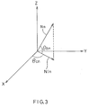
- Fig. 3 is an illustration showing an angle of a normal vector in an embodiment of the present invention; and,
- Fig. 4 is a flow chart of a calculation processing of a rotation command in an embodiment of the present invention.
- An embodiment of the present invention will hereinafter be described with reference to the drawings.
- Figure 1 is a block diagram showing a noncontact tracing control system and the peripheral constitution thereof according to the present invention. In Fig. 1, a processor 11 reads a system program stored in a
ROM 12, through abus 10, and controls the overall operation of atracing control system 1 according to this system program. ARAM 13 is used as a data temporary storing device and stores measured values from distance detectors, which will be described later, and other temporary data. Anonvolatile memory 14 is constituted by a CMOS backed up by a battery, and stores various parameters such as a tracing direction and tracing speed, etc. input from acontrol panel 2 through aninterface 15. - A tracer head 4 of a
tracing machine 3 is constituted bydistance detectors distance detectors model 6 without a contact therewith. Measured values La and Lb of these distance detectors are digital converted by A/D converters tracing control system 1, and sequentially read by the processor 11. - The processor 11 calculates displacement amounts of each axis based on the measured values La and Lb and signals from current position registers 19x, 19y, and 19z and generates speed commands Vx, Vy, and Vz of the respective axes based on these amounts of displacement, and commanded tracing direction and tracing speed, according to the known process. These speed commands are analog converted by D/
A converters 17x, 17y, and 17z and input toservo amplifiers servo amplifiers 18y drive servomotors tracing machine 3 based on these speed commands, to thereby move a table 31 in the X-axis direction and the Y-axis direction at right angles to the sheet surface. Also, the servo amplifier 18z drives theservomotor 32z, and acolumn 7 is moved in the Z-axis direction to maintain a constant distance between thedistance detector 5a and themodel 6, as mentioned later. -
Pulse coders servomotors - At the same time, the processor 11 samples the measured values La and Lb of the
distance detectors model 6 using this sampling data, and generates a rotation command Θc in the direction of an angle of a projection of the normal vector on the X-Y plane and a rotation command Θb in the direction of an angle of the normal vector against the X-Y plane. The rotation commands Θc and Θb are analog converted by D/A converters 17c and 17b, respectively, and input toservo amplifiers 18c and 18b. Theservo amplifier 18c drives aservomotor 32c and the servo amplifier 18b drives aservomotor 32b. - When the
servomotor 32b is driven, the tracer head 4 is rotated in the B1 axis direction, with the rotation center of a measured point P1 being at ameasuring axis 51, a predetermined distance from thedistance detector 5a, through adrive mechanism 36 constituted by a pinion gear and an arc-shaped rack gear. Also, when theservomotor 32c is driven to rotate in the C1 axis direction, with themeasuring axis 51 of thedistance detector 5a as the center, by thedrive mechanism 36, thedistance detector 5b is rotated by the same angle of the circumference of a predetermined radius. During this rotation, a point P1 (intersection of the centers of the C1 and the B1 axes) is controlled to be constantly positioned on the surface of themodel 6, by the above-mentioned Z-axis control, and at the same time, the table 31 is moved in the commanded tracing direction at the commanded speed to enable aworkpiece 35 to be machined to the same shape as that of themodel 6, by acutter 34 attached to thecolumn 7. - Next, the obtaining of the rotation commands Θc and Θb will be explained. In Fig. 2, the tracing is carried out by moving the tracer head 4 in the X-axis direction relative to the
model 6 and at a predetermined speed, the measured values of thedistance detectors model 6 are obtained based on these measured values and the current position data output from the current position registers. - Further, for example, a surface vector S1n [X2n - X1n, Y2n - Y1n, Z2n - Z1n] is obtained from the coordinate value of the point P1n (X1n, Y1n, Z1n) and the coordinate value of the point P2n (X2n, Y2n, Z2n), and a surface vector S2n [X1n-1 - X1n, Y1n-1 - Y1n, Z1n-1 - Z1n] is obtained from the coordinate value of the point P1n (X1n, Y1n, Z1n) and the coordinate value of the point P1n-1 (X1n-1, Y1n-1, Z1n-1).
- Next, a normal vector Nn at the point Pn is obtained by deriving an outer product of the surface vectors S1n and S2n from the following equation:

Then, an angle Θcn between the X-axis and a projection N1n of the normal vector Nn projected on the X-Y plane is obtained by the following equation, and the angle Θcn is output as a command value for the C1 axis:
In: X component of the vector Nn;
Jn: Y component of the vector Nn. - Also, an angle Θbn between the normal vector Nn and the X-Y plane is obtained by the following equation, and this angle Θbn is output as a command value for the B1 axis:

Kn: Z component of the vector Nn. - As a result, the measuring axes of the
distance detectors model 6, and thus a distance measuring having a high accuracy is obtained. - Figure 4 is a flow chart of a calculation processing of the rotation commands in an embodiment according to the present invention. In Fig. 4, the numerical values following the letter S show step numbers.
- [S1] The measured values of the
distance detectors - [S2] The surface vector S1 is obtained from the measured values of the respective distance detectors at the present time.
- [S3] The surface vector S2 is obtained from the measured values of the
distance detector 5a, at the present time and at the previous time. - [S4] The normal vector N is obtained by deriving an outer product of the surface vector S1 and the surface vector S2.
- [S5] The angle Θc between the X-axis and the projection of the normal vector N projected on the X-Y plane is calculated.
- [S6] The angle Θb between the normal vector N and the X-Y plane is calculated.
- Note, the normal vector was obtained based on the measured value of one of the distance detectors at the previous sampling and the measured values of both of the distance detectors at the present sampling in the above embodiment, but this is not limited thereto in that the normal direction can be also obtained from at least three points by other combinations of the four measured values obtained by sampling at the present time and at the previous time.
- Also, other than reflected light amount type of detector, an optical trigonometrical type, eddy-current type, or ultrasonic type distance detector can be used as the distance detector.
- Note, as a cutter has a radius but a noncontact sensor measures a "point" on a model, there is no guarantee that the same point as the measured point will be cut, but if the cutter diameter is small enough, the difference between the measured point and the cutting point can be ignored.
- On the other hand, for the digitising, the whole shape of a model can be reproduced as numerical data by obtaining successive points on the model, and thus a tracing control system using a noncontact sensor has a greater effect when applied to a digitizing system.
- According to the present invention as described above, a normal direction on a model surface is obtained based on measured values from two noncontact distance detectors at the previous sampling and the present sampling and the rotation of a tracer head is controlled in this direction, and therefore, the measuring axes of the noncontact distance detectors are always at a right angle to the model surface, which enables a distance measuring with a high accuracy and improves tracing accuracy. Also, as no blind spot is generated due to interference with the model surface, a complicated three-dimensional model can be traced.
Claims (3)
- A non-contact tracing control system for machining or digitising a workpiece through tracing the shape of a model (6) without contact therewith, the system comprising:
a tracing head (4) having first and second non-contact distance detectors (5a,5b) for measuring the distance to a model surface without contact therewith;
sampling means (11) for sampling measured values of each of the first and second non-contact distance detectors at predetermined sampling times;
storing means (13) for storing a first measured value of the first non-contact distance detector and a second measured value of the second non-contact distance detector at the previous sampling; and,
normal direction calculating means (11) for obtaining a normal direction of the model surface; characterised by:
the normal direction calculating means using at least three of (i) the first measured value, (ii) the second measured value, (iii) a third measured value of the first non-contact distance detector, and (iv) a fourth measured value of the second non-contact distance detector of the present sampling, the normal direction calculating means calculating the normal direction by obtaining coordinate values of three points on the model surface using the three measured values, by obtaining first and second vectors heading from one point of the three coordinate values to the other two points, and by operating a vector product between the first and second vectors;
means for controlling the inclinations of respective measuring axes of the first and second non-contact distance detectors to the model surface to be constant using first and second rotation axes (C1,B1) which cross each other, the second axis (B1) being inclined to the first axis (C1); and by:
rotation axis drive means (32c,32b) for rotating the tracing head (4) about the first rotation axis (C1) and the second rotation axis (B1) by angles determined according to said calculated normal direction. - A system according to claim 1, wherein the tracing machining or digitising is executed by calculating a displacement amount based on measured values of at least one of the first and second non-contact distance detectors.
- A system according to claim 1 or claim 2, wherein the first and second non-contact distance detectors are optical distance detectors.
Applications Claiming Priority (3)
| Application Number | Priority Date | Filing Date | Title |
|---|---|---|---|
| JP259824/89 | 1989-10-04 | ||
| JP1259824A JPH03121754A (en) | 1989-10-04 | 1989-10-04 | Noncontact tracing control device |
| PCT/JP1990/001226 WO1991004833A1 (en) | 1989-10-04 | 1990-09-21 | Non-contact profile control apparatus |
Publications (3)
| Publication Number | Publication Date |
|---|---|
| EP0446370A1 EP0446370A1 (en) | 1991-09-18 |
| EP0446370A4 EP0446370A4 (en) | 1992-03-04 |
| EP0446370B1 true EP0446370B1 (en) | 1995-07-19 |
Family
ID=17339503
Family Applications (1)
| Application Number | Title | Priority Date | Filing Date |
|---|---|---|---|
| EP90913890A Expired - Lifetime EP0446370B1 (en) | 1989-10-04 | 1990-09-21 | Non-contact profile control apparatus |
Country Status (5)
| Country | Link |
|---|---|
| US (1) | US5241485A (en) |
| EP (1) | EP0446370B1 (en) |
| JP (1) | JPH03121754A (en) |
| DE (1) | DE69021041T2 (en) |
| WO (1) | WO1991004833A1 (en) |
Families Citing this family (12)
| Publication number | Priority date | Publication date | Assignee | Title |
|---|---|---|---|---|
| JPH0482658A (en) * | 1990-07-25 | 1992-03-16 | Fanuc Ltd | Non-contact profile control unit |
| JPH04115854A (en) * | 1990-09-07 | 1992-04-16 | Fanuc Ltd | Noncontact profile control unit |
| JPH04241603A (en) * | 1991-01-14 | 1992-08-28 | Fanuc Ltd | Non-contact digitizing method |
| JPH04256554A (en) * | 1991-02-06 | 1992-09-11 | Fanuc Ltd | Non-contact digitizing control unit |
| JPH0531653A (en) * | 1991-07-26 | 1993-02-09 | Fanuc Ltd | Non-contact profile control method |
| JPH05104413A (en) * | 1991-10-16 | 1993-04-27 | Fanuc Ltd | Digitizing control device |
| US5550330A (en) * | 1991-10-16 | 1996-08-27 | Fanuc Limited | Digitizing control apparatus |
| US6535794B1 (en) | 1993-02-23 | 2003-03-18 | Faro Technologoies Inc. | Method of generating an error map for calibration of a robot or multi-axis machining center |
| JP4216211B2 (en) | 2004-03-10 | 2009-01-28 | ファナック株式会社 | Processing apparatus and processing method |
| JP2006007369A (en) * | 2004-06-25 | 2006-01-12 | Nippei Toyama Corp | Surface shape determining device for object to be measured in machine tool |
| US20060206233A1 (en) * | 2005-03-09 | 2006-09-14 | Carpenter David A | Method and apparatus for cutting a workpiece |
| JP5936039B2 (en) | 2012-02-29 | 2016-06-15 | 三菱重工業株式会社 | Normal detection method, normal detection device, and processing machine with normal detection function |
Family Cites Families (12)
| Publication number | Priority date | Publication date | Assignee | Title |
|---|---|---|---|---|
| JPS61274853A (en) * | 1985-05-28 | 1986-12-05 | Shin Meiwa Ind Co Ltd | Layout line follow-up device |
| JPS61274852A (en) * | 1985-05-28 | 1986-12-05 | Agency Of Ind Science & Technol | Non-contact curved surface copying sensor |
| JPS6215063A (en) * | 1985-07-10 | 1987-01-23 | Shin Meiwa Ind Co Ltd | Distance and attitude controller of ruled line followup device |
| JPH0729257B2 (en) * | 1987-07-31 | 1995-04-05 | ファナック株式会社 | Digitizing device |
| JP2542631B2 (en) * | 1987-09-02 | 1996-10-09 | ファナック株式会社 | Non-contact tracing method |
| JP2594578B2 (en) * | 1987-10-23 | 1997-03-26 | ファナック株式会社 | Non-contact profile control device |
| JPH01109057A (en) * | 1987-10-23 | 1989-04-26 | Fanuc Ltd | Digitizing method |
| IT212380Z2 (en) * | 1987-10-26 | 1989-07-04 | Advanced Data Processing | MACHINE FOR THE DETECTION AND MATHEMATIZATION OF THE SURFACE OF THREE-DIMENSIONAL MODELS I PARTICULARLY PART FOR THE CONSTRUCTION OF MOLDS WITH NUMERICALLY CONTROLLED TOOL MACHINES |
| JP2807461B2 (en) * | 1988-01-08 | 1998-10-08 | ファナック 株式会社 | Three-dimensional shape processing laser device |
| JPH0248152A (en) * | 1988-08-03 | 1990-02-16 | Osaka Kiko Co Ltd | Non-contact measuring apparatus |
| JPH0288152A (en) * | 1988-09-24 | 1990-03-28 | Toshiba Corp | Positioning device |
| JP2810709B2 (en) * | 1989-07-27 | 1998-10-15 | ファナック 株式会社 | Non-contact profile control device |
-
1989
- 1989-10-04 JP JP1259824A patent/JPH03121754A/en active Pending
-
1990
- 1990-09-21 WO PCT/JP1990/001226 patent/WO1991004833A1/en active IP Right Grant
- 1990-09-21 DE DE69021041T patent/DE69021041T2/en not_active Expired - Fee Related
- 1990-09-21 EP EP90913890A patent/EP0446370B1/en not_active Expired - Lifetime
-
1991
- 1991-09-21 US US07/689,933 patent/US5241485A/en not_active Expired - Fee Related
Also Published As
| Publication number | Publication date |
|---|---|
| JPH03121754A (en) | 1991-05-23 |
| EP0446370A1 (en) | 1991-09-18 |
| DE69021041D1 (en) | 1995-08-24 |
| EP0446370A4 (en) | 1992-03-04 |
| DE69021041T2 (en) | 1995-11-30 |
| US5241485A (en) | 1993-08-31 |
| WO1991004833A1 (en) | 1991-04-18 |
Similar Documents
| Publication | Publication Date | Title |
|---|---|---|
| EP0436735B1 (en) | Noncontact profile control unit | |
| EP0446370B1 (en) | Non-contact profile control apparatus | |
| EP0428739B1 (en) | Digitizing controller | |
| EP0510208B1 (en) | Digitizing control device | |
| EP0511399B1 (en) | Equipment for controlling digitizing | |
| KR950014515B1 (en) | Device for controlling non-contact digitizing | |
| EP0506966B1 (en) | Non-contact copy control device | |
| EP0494314B1 (en) | Non-contact copy control device | |
| EP0520075B1 (en) | Non-contact digitizing method | |
| EP0563407B1 (en) | Digitizing controller | |
| US5209618A (en) | Method of setting tracing zone | |
| JPS6056848A (en) | Machining data producing system | |
| WO1994004311A1 (en) | Non-contact profile control method | |
| JPH0679588A (en) | Noncontact tractor controller | |
| JPH04189453A (en) | Profile control device |
Legal Events
| Date | Code | Title | Description |
|---|---|---|---|
| PUAI | Public reference made under article 153(3) epc to a published international application that has entered the european phase |
Free format text: ORIGINAL CODE: 0009012 |
|
| 17P | Request for examination filed |
Effective date: 19910621 |
|
| AK | Designated contracting states |
Kind code of ref document: A1 Designated state(s): DE FR GB IT |
|
| A4 | Supplementary search report drawn up and despatched |
Effective date: 19920115 |
|
| AK | Designated contracting states |
Kind code of ref document: A4 Designated state(s): DE FR GB IT |
|
| 17Q | First examination report despatched |
Effective date: 19921002 |
|
| GRAA | (expected) grant |
Free format text: ORIGINAL CODE: 0009210 |
|
| AK | Designated contracting states |
Kind code of ref document: B1 Designated state(s): DE FR GB IT |
|
| PG25 | Lapsed in a contracting state [announced via postgrant information from national office to epo] |
Ref country code: FR Effective date: 19950719 |
|
| ITF | It: translation for a ep patent filed |
Owner name: JACOBACCI & PERANI S.P.A. |
|
| REF | Corresponds to: |
Ref document number: 69021041 Country of ref document: DE Date of ref document: 19950824 |
|
| PG25 | Lapsed in a contracting state [announced via postgrant information from national office to epo] |
Ref country code: GB Effective date: 19951019 |
|
| EN | Fr: translation not filed | ||
| PLBE | No opposition filed within time limit |
Free format text: ORIGINAL CODE: 0009261 |
|
| STAA | Information on the status of an ep patent application or granted ep patent |
Free format text: STATUS: NO OPPOSITION FILED WITHIN TIME LIMIT |
|
| GBPC | Gb: european patent ceased through non-payment of renewal fee |
Effective date: 19951019 |
|
| 26N | No opposition filed | ||
| PGFP | Annual fee paid to national office [announced via postgrant information from national office to epo] |
Ref country code: DE Payment date: 19960927 Year of fee payment: 7 |
|
| PG25 | Lapsed in a contracting state [announced via postgrant information from national office to epo] |
Ref country code: DE Free format text: LAPSE BECAUSE OF NON-PAYMENT OF DUE FEES Effective date: 19980603 |
|
| PG25 | Lapsed in a contracting state [announced via postgrant information from national office to epo] |
Ref country code: IT Free format text: LAPSE BECAUSE OF NON-PAYMENT OF DUE FEES;WARNING: LAPSES OF ITALIAN PATENTS WITH EFFECTIVE DATE BEFORE 2007 MAY HAVE OCCURRED AT ANY TIME BEFORE 2007. THE CORRECT EFFECTIVE DATE MAY BE DIFFERENT FROM THE ONE RECORDED. Effective date: 20050921 |