EP0446080A1 - Method and device for elemental analysis of a sample by mass spectrometry coupled to a high frequency induced plasma - Google Patents
Method and device for elemental analysis of a sample by mass spectrometry coupled to a high frequency induced plasma Download PDFInfo
- Publication number
- EP0446080A1 EP0446080A1 EP91400001A EP91400001A EP0446080A1 EP 0446080 A1 EP0446080 A1 EP 0446080A1 EP 91400001 A EP91400001 A EP 91400001A EP 91400001 A EP91400001 A EP 91400001A EP 0446080 A1 EP0446080 A1 EP 0446080A1
- Authority
- EP
- European Patent Office
- Prior art keywords
- plasma
- sample
- cones
- installation
- gas
- Prior art date
- Legal status (The legal status is an assumption and is not a legal conclusion. Google has not performed a legal analysis and makes no representation as to the accuracy of the status listed.)
- Granted
Links
- 238000000034 method Methods 0.000 title claims abstract description 7
- 238000004949 mass spectrometry Methods 0.000 title claims abstract description 5
- 238000000921 elemental analysis Methods 0.000 title abstract 2
- 238000009434 installation Methods 0.000 claims abstract description 19
- 239000010936 titanium Substances 0.000 claims abstract description 13
- 230000006872 improvement Effects 0.000 claims abstract description 9
- RTAQQCXQSZGOHL-UHFFFAOYSA-N Titanium Chemical compound [Ti] RTAQQCXQSZGOHL-UHFFFAOYSA-N 0.000 claims abstract description 4
- 229910052735 hafnium Inorganic materials 0.000 claims abstract description 4
- VBJZVLUMGGDVMO-UHFFFAOYSA-N hafnium atom Chemical compound [Hf] VBJZVLUMGGDVMO-UHFFFAOYSA-N 0.000 claims abstract description 4
- 229910052719 titanium Inorganic materials 0.000 claims abstract description 4
- 230000008021 deposition Effects 0.000 claims abstract 2
- 239000007789 gas Substances 0.000 claims description 21
- XKRFYHLGVUSROY-UHFFFAOYSA-N Argon Chemical compound [Ar] XKRFYHLGVUSROY-UHFFFAOYSA-N 0.000 claims description 14
- 238000005070 sampling Methods 0.000 claims description 13
- 238000004458 analytical method Methods 0.000 claims description 8
- 239000001257 hydrogen Substances 0.000 claims description 8
- 229910052739 hydrogen Inorganic materials 0.000 claims description 8
- 229910052786 argon Inorganic materials 0.000 claims description 7
- 229910045601 alloy Inorganic materials 0.000 claims description 6
- 239000000956 alloy Substances 0.000 claims description 6
- 238000002347 injection Methods 0.000 claims description 6
- 239000007924 injection Substances 0.000 claims description 6
- 239000000463 material Substances 0.000 claims description 5
- 230000008569 process Effects 0.000 claims description 4
- 230000015572 biosynthetic process Effects 0.000 claims description 3
- 238000003754 machining Methods 0.000 claims description 2
- 125000004435 hydrogen atom Chemical group [H]* 0.000 claims 1
- 229910001257 Nb alloy Inorganic materials 0.000 abstract description 2
- 150000002500 ions Chemical class 0.000 description 17
- PXHVJJICTQNCMI-UHFFFAOYSA-N Nickel Chemical compound [Ni] PXHVJJICTQNCMI-UHFFFAOYSA-N 0.000 description 12
- BLRPTPMANUNPDV-UHFFFAOYSA-N Silane Chemical compound [SiH4] BLRPTPMANUNPDV-UHFFFAOYSA-N 0.000 description 7
- XUIMIQQOPSSXEZ-UHFFFAOYSA-N Silicon Chemical compound [Si] XUIMIQQOPSSXEZ-UHFFFAOYSA-N 0.000 description 5
- 239000000203 mixture Substances 0.000 description 5
- 229910052759 nickel Inorganic materials 0.000 description 5
- 229910000077 silane Inorganic materials 0.000 description 5
- 229910052710 silicon Inorganic materials 0.000 description 5
- 239000010703 silicon Substances 0.000 description 5
- UFHFLCQGNIYNRP-UHFFFAOYSA-N Hydrogen Chemical compound [H][H] UFHFLCQGNIYNRP-UHFFFAOYSA-N 0.000 description 4
- 238000009616 inductively coupled plasma Methods 0.000 description 4
- 238000005259 measurement Methods 0.000 description 4
- 239000000243 solution Substances 0.000 description 4
- XEEYBQQBJWHFJM-UHFFFAOYSA-N Iron Chemical compound [Fe] XEEYBQQBJWHFJM-UHFFFAOYSA-N 0.000 description 3
- 125000004429 atom Chemical group 0.000 description 3
- 238000001514 detection method Methods 0.000 description 3
- 150000002431 hydrogen Chemical class 0.000 description 3
- 230000006698 induction Effects 0.000 description 3
- 239000010955 niobium Substances 0.000 description 3
- 239000010453 quartz Substances 0.000 description 3
- VYPSYNLAJGMNEJ-UHFFFAOYSA-N silicon dioxide Inorganic materials O=[Si]=O VYPSYNLAJGMNEJ-UHFFFAOYSA-N 0.000 description 3
- 239000011575 calcium Substances 0.000 description 2
- 230000000694 effects Effects 0.000 description 2
- 230000005284 excitation Effects 0.000 description 2
- INQOMBQAUSQDDS-UHFFFAOYSA-N iodomethane Chemical compound IC INQOMBQAUSQDDS-UHFFFAOYSA-N 0.000 description 2
- 230000003902 lesion Effects 0.000 description 2
- 239000007788 liquid Substances 0.000 description 2
- 229910052751 metal Inorganic materials 0.000 description 2
- 230000009467 reduction Effects 0.000 description 2
- 239000004065 semiconductor Substances 0.000 description 2
- 239000011734 sodium Substances 0.000 description 2
- ZOXJGFHDIHLPTG-UHFFFAOYSA-N Boron Chemical compound [B] ZOXJGFHDIHLPTG-UHFFFAOYSA-N 0.000 description 1
- OYPRJOBELJOOCE-UHFFFAOYSA-N Calcium Chemical compound [Ca] OYPRJOBELJOOCE-UHFFFAOYSA-N 0.000 description 1
- DGAQECJNVWCQMB-PUAWFVPOSA-M Ilexoside XXIX Chemical compound C[C@@H]1CC[C@@]2(CC[C@@]3(C(=CC[C@H]4[C@]3(CC[C@@H]5[C@@]4(CC[C@@H](C5(C)C)OS(=O)(=O)[O-])C)C)[C@@H]2[C@]1(C)O)C)C(=O)O[C@H]6[C@@H]([C@H]([C@@H]([C@H](O6)CO)O)O)O.[Na+] DGAQECJNVWCQMB-PUAWFVPOSA-M 0.000 description 1
- WHXSMMKQMYFTQS-UHFFFAOYSA-N Lithium Chemical compound [Li] WHXSMMKQMYFTQS-UHFFFAOYSA-N 0.000 description 1
- FLHROXIJCMGCJH-UHFFFAOYSA-N [Ti].[Hf].[Nb] Chemical compound [Ti].[Hf].[Nb] FLHROXIJCMGCJH-UHFFFAOYSA-N 0.000 description 1
- 229910052785 arsenic Inorganic materials 0.000 description 1
- RQNWIZPPADIBDY-UHFFFAOYSA-N arsenic atom Chemical compound [As] RQNWIZPPADIBDY-UHFFFAOYSA-N 0.000 description 1
- 238000000889 atomisation Methods 0.000 description 1
- 230000008901 benefit Effects 0.000 description 1
- 238000009835 boiling Methods 0.000 description 1
- 229910052796 boron Inorganic materials 0.000 description 1
- 229910052791 calcium Inorganic materials 0.000 description 1
- 230000008859 change Effects 0.000 description 1
- 229910052729 chemical element Inorganic materials 0.000 description 1
- 230000002301 combined effect Effects 0.000 description 1
- 238000001816 cooling Methods 0.000 description 1
- 239000012809 cooling fluid Substances 0.000 description 1
- 238000000151 deposition Methods 0.000 description 1
- 238000004807 desolvation Methods 0.000 description 1
- 230000006870 function Effects 0.000 description 1
- 230000001771 impaired effect Effects 0.000 description 1
- 239000012535 impurity Substances 0.000 description 1
- 230000010354 integration Effects 0.000 description 1
- 229910052742 iron Inorganic materials 0.000 description 1
- 239000006193 liquid solution Substances 0.000 description 1
- 229910052744 lithium Inorganic materials 0.000 description 1
- 238000004519 manufacturing process Methods 0.000 description 1
- 239000002184 metal Substances 0.000 description 1
- 239000003595 mist Substances 0.000 description 1
- 229910052758 niobium Inorganic materials 0.000 description 1
- GUCVJGMIXFAOAE-UHFFFAOYSA-N niobium atom Chemical compound [Nb] GUCVJGMIXFAOAE-UHFFFAOYSA-N 0.000 description 1
- 238000005086 pumping Methods 0.000 description 1
- 150000003377 silicon compounds Chemical class 0.000 description 1
- 229910052708 sodium Inorganic materials 0.000 description 1
- 239000000758 substrate Substances 0.000 description 1
- XLYOFNOQVPJJNP-UHFFFAOYSA-N water Substances O XLYOFNOQVPJJNP-UHFFFAOYSA-N 0.000 description 1
Images
Classifications
-
- H—ELECTRICITY
- H01—ELECTRIC ELEMENTS
- H01J—ELECTRIC DISCHARGE TUBES OR DISCHARGE LAMPS
- H01J49/00—Particle spectrometers or separator tubes
- H01J49/02—Details
- H01J49/10—Ion sources; Ion guns
- H01J49/105—Ion sources; Ion guns using high-frequency excitation, e.g. microwave excitation, Inductively Coupled Plasma [ICP]
-
- H—ELECTRICITY
- H01—ELECTRIC ELEMENTS
- H01J—ELECTRIC DISCHARGE TUBES OR DISCHARGE LAMPS
- H01J49/00—Particle spectrometers or separator tubes
- H01J49/02—Details
- H01J49/04—Arrangements for introducing or extracting samples to be analysed, e.g. vacuum locks; Arrangements for external adjustment of electron- or ion-optical components
- H01J49/0468—Arrangements for introducing or extracting samples to be analysed, e.g. vacuum locks; Arrangements for external adjustment of electron- or ion-optical components with means for heating or cooling the sample
-
- H—ELECTRICITY
- H01—ELECTRIC ELEMENTS
- H01J—ELECTRIC DISCHARGE TUBES OR DISCHARGE LAMPS
- H01J49/00—Particle spectrometers or separator tubes
- H01J49/02—Details
- H01J49/06—Electron- or ion-optical arrangements
- H01J49/067—Ion lenses, apertures, skimmers
-
- G—PHYSICS
- G01—MEASURING; TESTING
- G01N—INVESTIGATING OR ANALYSING MATERIALS BY DETERMINING THEIR CHEMICAL OR PHYSICAL PROPERTIES
- G01N30/00—Investigating or analysing materials by separation into components using adsorption, absorption or similar phenomena or using ion-exchange, e.g. chromatography or field flow fractionation
- G01N30/02—Column chromatography
- G01N30/62—Detectors specially adapted therefor
- G01N30/72—Mass spectrometers
- G01N30/7206—Mass spectrometers interfaced to gas chromatograph
Definitions
- the present invention relates to an improvement to the known method of analysis of a gas sample by a plasma induced by high frequency, forming a source of ions taken from a mass spectrometer and also relates to an improvement made to the installation. necessary for the implementation of this process.
- the process consists in particular, from a torch formed of a quartz tube receiving a sample to analyze gas or solution previously nebulized and a plasmagenic medium delivered in a ring around the central injection of the sample in the axis of the torch, to establish the plasma by means of a high frequency induction device coaxial with the torch, allowing the output of the latter to excite the gas mixture and to collect a flow of ions, which is then delivered to a sampling device, itself in relation to a mass spectrometer.
- this device comprises two successive cones, generally made of nickel, these cones arranged one behind the other along the axis of the torch, each being provided with an axial orifice to collect a fraction of the flow of ions to be analyzed.
- the first, more open cone is called the sampling cone and is joined to a support member, generally cooled by a continuous circulation of an appropriate refrigerating medium, the second cone, located downstream of the first, being designated under the sampling cone term.
- a majority fraction of the gas flow is evacuated by a pump or the like while the remainder, after passing through the second cone, is admitted into a chamber placed under a high vacuum, of sufficient dimensions to allow the free passage of ions which are then collected by the mass spectrometer where they are detected as a function of the ratio of their mass to their charge.
- the present invention relates to an improvement made to the elementary analysis method of a sample by mass spectrometry, coupled to a plasma induced by high frequency, which overcomes the aforementioned drawback, by limiting the plugging of the cone through orifices. of the installation and a reduction in the signal supplied by the mass spectrometer, a reduction in signal which could possibly be slightly offset by a change in the settings of the ion optics, which cannot however be modified during an analysis.
- the improvement considered is characterized in that it consists in adding to the sample injected into the plasma a given quantity of a make-up gas, with high calorific value, so as to raise the temperature of the plasma for locally heat the sampling cones in order to avoid depositing on them the components of the sample, present in the plasma.
- the temperature of the plasma formed which depends on its electronic density and on its composition, can be appreciably increased by the introduction into the plasma medium and / or the sample injected into the plasma, of an additional contribution d '' a gas with high calorific value, providing in particular an improvement in energy transfers between the plasma and the components of the sample.
- the excitation temperature of the plasma can thus be increased from 5000 to 7000 ° K, simply by adding an appropriate flow of hydrogen.
- the effect of the increase in plasma temperatures is combined with that which results from an appropriate choice of the material of cones carrying out the sampling and the admission of a fraction of the sample to the mass spectrometer.
- the material of the cones is determined so that it has refractory properties at high temperature and satisfactory machining properties for producing the necessary profiles of these cones.
- the cones are made of an alloy of niobium Nb, hafnium Hf, titanium Ti, the relative proportions of these three metallic elements being close to 89% (Nb), 10% respectively. (Hf) and 1% (Ti).
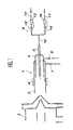
- the installation shown in the figures repeats arrangements known in the art in conventional installations of the ICP / MS type, comprising in particular an injection torch 1, placed opposite a connection structure 2 with a mass spectrometer, not shown in the drawing.
- the torch 1 mainly comprises a quartz tube 3, associated in its outer surface with a high frequency induction coil 4, allowing the creation of a plasma inductively coupled with a gaseous medium injected into the torch with an appropriate flow rate.
- the torch 1 comprises means of admission, of the sample and of the plasmagenic medium, consisting of a tube 5, arranged concentrically in the tube 3 and itself comprising axially an inlet pipe 6.
- the plasmagenic medium is introduced by a connection 7, between the tubing 5 and the internal surface of the quartz tube 3, another connection 8 also making it possible to introduce, inside the tubing 5, an auxiliary flow another gas or the same gas as that which constitutes the plasma medium, in order to adjust the conditions of plasma formation in the torch, in line with the induction coil 4.
- the axial pipe 6 is connected to an assembly 9 for introducing the sample into the installation, comprising two parallel lines, respectively 10 and 11, joined together to a single connection line 12 with the pipe 6.
- the gaseous sample to be analyzed is delivered by line 10 through a valve 12 provided with a servo-control and flow-regulating device 13.
- This sample can be of any kind and, in addition, be in gaseous form or in the form of a liquid solution, the latter being previously nebulized to constitute a mist of very fine droplets.
- an auxiliary flow of a gas with high calorific value preferably from the second line 11, also provided with a valve 14 and a servo-control 15, is introduced. hydrogen, which thus mixes with the sample in the connection line 12 before being injected into the pipe 6 in the axis of the torch 1.
- the gas sample intimately mixed with the additional hydrogen thus supplied is injected into the plasma, part of which is taken to be sent to the connection structure 2 with the mass spectrometer, performing the desired quantitative elementary analysis of the components of the sample.
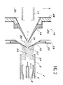
- the sampling of the necessary fraction of the sample is carried out through an interface 16, arranged at the outlet of the torch 1 and before the first electrodes 17 of the electronic optics, making it possible to convey this sampling to spectrometer.
- the interface 16 comprises two successive cones, respectively 18 and 19, placed coaxially one behind the other, the first cone 18 being called the sampling cone, while the second is designated by the term cone direct debit.
- the cones 18 and 19 each have a central orifice, respectively 20 and 21, the sampling cone 18 having a larger aperture at the top than the sampling cone 19.
- the cone 18 is secured to a support jacket 22, hollowed out internally at 23 to allow the circulation of a cone cooling fluid, generally water.
- the cone 19 is carried by a mounting structure 24 which closes a chamber 25 in which the ions taken through the orifices 20 and 21 are taken up by the electrodes 17 which accelerate them towards the spectrometer.
- the chamber 25 is placed under a high vacuum.
- a space 26 also placed under vacuum but lower than that prevailing in the chamber 25, this space 26 being joined to a pumping installation (not shown).
- the plasma jet 27 thus leaving the torch 1 surrounds an axial zone 28, where the gas sample coming from the pipe 6 is strongly ionized; a large fraction of the sample is removed outward along the surface of the first cone 18, while the remainder enters through the orifice 20 into the space 26 where it forms an expansion zone 29, the part central of it entering the chamber 25 through the orifice 21.
- the addition of a gas with high calorific value, in particular hydrogen, in the initial gas sample makes it possible to raise the temperature of the plasma and consequently to locally heat the successive cones 18 and 19, in particular by preventing the orifices 20 and 21 from being progressively obstructed by the deposits of the components of the sample, the temperature of these cones being, in all cases, substantially lower than that which prevails within the plasma.
- a gas with high calorific value in particular hydrogen
- the cones 18 and 19 are thus made of a niobium (89%), hafnium (10%), titanium (1%) alloy.
- the deposits formed on the apertures of the cones are also the main cause of the low value of the average intensity of the 127I ion in the case of cones made of Ni.
- a gain of a factor of 5 is obtained with respect to the intensity of the 127I ion, found with the nickel cones.
Landscapes
- Chemical & Material Sciences (AREA)
- Analytical Chemistry (AREA)
- Physics & Mathematics (AREA)
- Engineering & Computer Science (AREA)
- Plasma & Fusion (AREA)
- Other Investigation Or Analysis Of Materials By Electrical Means (AREA)
- Electron Tubes For Measurement (AREA)
- Investigating, Analyzing Materials By Fluorescence Or Luminescence (AREA)
- Plasma Technology (AREA)
- Sampling And Sample Adjustment (AREA)
Abstract
Description
La présente invention se rapporte à un perfectionnement au procédé connu d'analyse d'un échantillon de gaz par un plasma induit par haute fréquence, formant une source d'ions prélevés dans un spectromètre de masse et concerne également une amélioration apportée à l'installation nécessaire à la mise en oeuvre de ce procédé.The present invention relates to an improvement to the known method of analysis of a gas sample by a plasma induced by high frequency, forming a source of ions taken from a mass spectrometer and also relates to an improvement made to the installation. necessary for the implementation of this process.
On sait que l'analyse élémentaire de certains échantillons, en particulier de composants gazeux ou en solution, est de plus en en plus souvent rendue nécessaire avec des moyens très précis, afin de contrôler de manière extrêmement approfondie la pureté de ces composants. Plus particulièrement mais de façon non exclusive, on sait que dans certaines applications de l'électronique, notamment pour la fabrication de produits semi-conducteurs à très haute intégration, il est indispensable de réaliser des dépôts de silicium extrêmement purs et dont la composition doit rester rigoureusement constante dans le temps. Généralement, on obtient de tels dépôts à partir d'un composé de silicium, notamment de silane, de formule SiH4, évaporé et déposé sous vide sur un substrat. Or, la qualité du dépôt réalisé peut être gravement altérée par la présence dans le silane d'éléments chimiques tels que le lithium Li, le sodium Na, le fer Fe, le calcium Ca, l'arsenic As, le bore B, etc..., qui modifient les propriétés semi-conductrices du dépôt de silicium, parfois de façon considérable, même avec des concentrations relativement très faibles. On conçoit donc l'intérêt de pouvoir, à tout moment, faire une analyse élémentaire très poussée du gaz ou de la solution utilisés.It is known that the elementary analysis of certain samples, in particular of gaseous components or in solution, is more and more often made necessary with very precise means, in order to control in an extremely thorough way the purity of these components. More particularly but not exclusively, it is known that in certain applications of electronics, in particular for the manufacture of semiconductor products with very high integration, it is essential to make deposits of extremely pure silicon and the composition of which must remain rigorously constant over time. Generally, such deposits are obtained from a silicon compound, in particular silane, of formula SiH4, evaporated and deposited under vacuum on a substrate. However, the quality of the deposit produced can be seriously impaired by the presence in the silane of chemical elements such as lithium Li, sodium Na, iron Fe, calcium Ca, arsenic As, boron B, etc. .., which modify the semiconductor properties of the silicon deposit, sometimes considerably, even with relatively very low concentrations. We can therefore understand the advantage of being able, at any time, to make a very thorough elementary analysis of the gas or solution used.
Dans ce but, il est classique d'utiliser pour effectuer une telle mesure, un spectromètre de masse couplé à un plasma induit par haute fréquence, ce système étant connu dans la technique sous le terme de ICP/MS, intiales de l'expression en langue anglaise "Inductively Coupled Plasma Mass Spectrometer". Le processus consiste en particulier, à partir d'une torche formée d'un tube de quartz recevant un échantillon à analyser du gaz ou de la solution préalablement nébulisée et un milieu plasmagène délivré en couronne autour de l'injection centrale de l'échantillon dans l'axe de la torche, à établir le plasma au moyen d'un dispositif d'induction à haute fréquence coaxial à la torche, en permettant à la sortie de celle-ci d'exciter le mélange gazeux et de recueillir un débit d'ions, qui est alors délivré à un dispositif d'échantillonnage, lui-même en relation avec un spectromètre de masse. De façon connue, ce dispositif comporte deux cônes successifs, généralement en nickel, ces cônes disposés l'un derrière l'autre selon l'axe de la torche, étant munis chacun d'un orifice axial pour recueillir une fraction du débit d'ions à analyser. Le premier cône, plus ouvert, est appelé cône d'échantillonnage et est solidarisé d'un organe de support, généralement refroidi par une circulation continue d'un milieu réfrigérant approprié, le second cône, situé en aval du premier, étant désigné sous le terme de cône de prélèvement. Entre les deux cônes, une fraction majoritaire du débit gazeux est évacuée par une pompe ou analogue tandis que le reliquat, après avoir traversé le second cône, est admis dans une chambre placée sous un vide poussé, de dimensions suffisantes pour permettre le libre passage des ions qui sont ensuite collectés par le spectromètre de masse où ils sont détectés en fonction du rapport de leur masse vis-à-vis de leur charge. Une telle installation, bien connue des spécialistes du domaine, est notamment décrite dans la revue "Analytical Chemistry, Vol. 58 N° 1, Janvier 1986 Pages 97 et seq".For this purpose, it is conventional to use to carry out such a measurement, a mass spectrometer coupled to a plasma induced by high frequency, this system being known in the art under the term of ICP / MS, initials of the expression in English language "Inductively Coupled Plasma Mass Spectrometer". The process consists in particular, from a torch formed of a quartz tube receiving a sample to analyze gas or solution previously nebulized and a plasmagenic medium delivered in a ring around the central injection of the sample in the axis of the torch, to establish the plasma by means of a high frequency induction device coaxial with the torch, allowing the output of the latter to excite the gas mixture and to collect a flow of ions, which is then delivered to a sampling device, itself in relation to a mass spectrometer. In known manner, this device comprises two successive cones, generally made of nickel, these cones arranged one behind the other along the axis of the torch, each being provided with an axial orifice to collect a fraction of the flow of ions to be analyzed. The first, more open cone is called the sampling cone and is joined to a support member, generally cooled by a continuous circulation of an appropriate refrigerating medium, the second cone, located downstream of the first, being designated under the sampling cone term. Between the two cones, a majority fraction of the gas flow is evacuated by a pump or the like while the remainder, after passing through the second cone, is admitted into a chamber placed under a high vacuum, of sufficient dimensions to allow the free passage of ions which are then collected by the mass spectrometer where they are detected as a function of the ratio of their mass to their charge. Such an installation, well known to specialists in the field, is described in particular in the review "Analytical Chemistry, Vol. 58 No. 1, January 1986 Pages 97 and seq".
Or l'expérience montre que, avec des échantillons contenant des concentrations élevées en ions du corps à analyser, tel que le silane SiH4, le transfert efficace et régulier des ions jusqu'au spectromètre de masse à travers les deux cônes d'interface, se heurte à certaines difficultés en raison du fait que dans le plasma les atomes (par exemple Si) ou les ions (par exemple Si +), créent rapidement un dépôt de silicium sur la surface externe des cônes eux-mêmes, obstruant partiellement leurs orifices de passage axiaux et perturbant dès lors très sensiblement l'analyse effectuée par le spectromètre de masse.However, experience shows that, with samples containing high concentrations of ions in the body to be analyzed, such as the silane SiH4, the efficient and regular transfer of the ions to the mass spectrometer through the two interface cones is encounters certain difficulties due to the fact that in the plasma the atoms (for example Si) or the ions (for example Si +), quickly create a deposit of silicon on the external surface of the cones themselves, partially obstructing their orifices axial passage and therefore very significantly disturbing the analysis performed by the mass spectrometer.
En effet, dans le plasma créé, consécutivement à la désolvatation de la solution dans le cas d'un échantillon liquide, dans tous les cas de l'atomisation de la molécule et de l'excitation des atomes, que l'échantillon soit liquide ou gazeux, les ions et les atomes sont nécessairement en phase gazeuse du fait de la température du plasma (généralement supérieure ou égale à 5000°K), largement plus élevée à celle de l'ébullition du corps, par exemple égale, dans le cas du silicium, à 2628°K. En revanche, du fait du refroidissement des cônes de nickel, le silicium se solidifie partiellement au contact de ces derniers, en créant ainsi un dépôt préjudiciable.In fact, in the plasma created, following the desolvation of the solution in the case of a liquid sample, in all cases of atomization of the molecule and excitation of atoms, whether the sample is liquid or gases, ions and atoms are necessarily in the gas phase due to the plasma temperature (generally greater than or equal to 5000 ° K), much higher than that of the boiling of the body, for example equal, in the case of silicon, at 2628 ° K. On the other hand, due to the cooling of the nickel cones, the silicon partially solidifies on contact with the latter, thereby creating a harmful deposit.
La présente invention a pour objet un perfectionnement apporté au procédé d'analyse élémentaire d'un échantillon par spectromètrie de masse, couplé à un plasma induit par haute fréquence, qui pallie l'inconvénient précité, en limitant le bouchage des orifices de traversée des cônes de l'installation et une diminution du signal fourni par le spectromètre de masse, diminution de signal qui pourrait être éventuellement légèrement compensée par un changement des réglages de l'optique ionique, qui ne peuvent toutefois être modifiés au cours d'une analyse.The present invention relates to an improvement made to the elementary analysis method of a sample by mass spectrometry, coupled to a plasma induced by high frequency, which overcomes the aforementioned drawback, by limiting the plugging of the cone through orifices. of the installation and a reduction in the signal supplied by the mass spectrometer, a reduction in signal which could possibly be slightly offset by a change in the settings of the ion optics, which cannot however be modified during an analysis.
A cet effet, le perfectionnement considéré se caractérise en ce qu'il consiste à ajouter à l'échantillon injecté dans le plasma une quantité donnée d'un gaz d'appoint, à haut pouvoir calorifique, de manière à élever la température du plasma pour chauffer localement les cônes de prélèvement afin d'éviter le dépôt sur ceux-ci des composants de l'échantillon, présents dans le plasma.To this end, the improvement considered is characterized in that it consists in adding to the sample injected into the plasma a given quantity of a make-up gas, with high calorific value, so as to raise the temperature of the plasma for locally heat the sampling cones in order to avoid depositing on them the components of the sample, present in the plasma.
On a constaté en effet que la température du plasma formé, qui dépend de sa densité électronique et de sa composition, peut être sensiblement augmentée par introduction dans le milieu plasmagène et/ou l'échantillon injecté dans le plasma, d'un apport complémentaire d'un gaz à haut pouvoir calorifique, procurant notamment une amélioration des transferts d'énergie entre le plasma et les composants de l'échantillon. Ainsi, avec un milieu plasmagène formé notamment d'argon, la température d'excitation du plasma peut ainsi être portée de 5000 à 7000°K, simplement par addition d'un débit approprié d'hydrogène.It has in fact been found that the temperature of the plasma formed, which depends on its electronic density and on its composition, can be appreciably increased by the introduction into the plasma medium and / or the sample injected into the plasma, of an additional contribution d '' a gas with high calorific value, providing in particular an improvement in energy transfers between the plasma and the components of the sample. Thus, with a plasmagenic medium formed in particular of argon, the excitation temperature of the plasma can thus be increased from 5000 to 7000 ° K, simply by adding an appropriate flow of hydrogen.
Par ailleurs et selon une autre caractéristique de l'invention, on combine l'effet de l'accroissement des températures du plasma à celui qui résulte d'un choix approprié du matériau de cônes réalisant le prélèvement et l'admission d'une fraction de l'échantillon vers le spectromètre de masse. De préférence le matériau des cônes est déterminé de telle sorte qu'il présente des propriétés réfractaires à haute température et des facultés satisfaisantes d'usinage pour la réalisation des profils nécessaires de ces cônes.Furthermore and according to another characteristic of the invention, the effect of the increase in plasma temperatures is combined with that which results from an appropriate choice of the material of cones carrying out the sampling and the admission of a fraction of the sample to the mass spectrometer. Preferably, the material of the cones is determined so that it has refractory properties at high temperature and satisfactory machining properties for producing the necessary profiles of these cones.
Avantageusement et dans un mode de réalisation particulier de l'invention, les cônes sont réalisés en un alliage de niobium Nb, hafnium Hf, titane Ti, les proportions relatives de ces trois éléments métalliques étant voisines respectivement de 89 % (Nb), 10 % (Hf) et 1 % (Ti).Advantageously and in a particular embodiment of the invention, the cones are made of an alloy of niobium Nb, hafnium Hf, titanium Ti, the relative proportions of these three metallic elements being close to 89% (Nb), 10% respectively. (Hf) and 1% (Ti).
D'autres caractéristiques d'une installation de spectrométrie de masse couplée à un plasma induit par haute fréquence (ICP/MS), perfectionnée conformément à l'invention, apparaîtront encore à travers la description qui suit d'un exemple de réalisation, donné ci-après à titre indicatif et non limitatif, en référence aux dessins annexés sur lesquels:
- La Figure 1 est une vue schématique en coupe tranversale de l'installation considérée,
- La Figure 2 est une vue de détail à plus grande échelle d'une partie de l'installation, illustrant plus particulièrement la structure des cônes de cette dernière.
- FIG. 1 is a schematic view in transverse section of the installation considered,
- Figure 2 is a detail view on a larger scale of a part of the installation, more particularly illustrating the structure of the cones of the latter.
L'installation représentée sur les figures reprend des dispositions connues dans la technique dans les installations classiques du type ICP/MS, comportant notamment une torche d'injection 1, placée en regard d'une structure de liaison 2 avec un spectromètre de masse, non figuré sur le dessin. La torche 1 comporte principalement un tube de quartz 3, associé dans sa surface extérieure à une bobine d'induction 4 à haute fréquence, permettant la création d'un plasma couplé inductivement avec un milieu gazeux injecté dans la torche avec un débit approprié. Avantageusement, la torche 1 comporte des moyens d'admission, de l'échantillon et du milieu plasmagène, constitués d'une tubulure 5, disposée concentriquement dans le tube 3 et comportant elle-même axialement une conduite d'admission 6. Le milieu plasmagène, généralement de l'argon, est introduit par une liaison 7, entre la tubulure 5 et la surface interne du tube de quartz 3, une autre liaison 8 permettant également d'introduire, à l'intérieur de la tubulure 5, un débit auxiliaire d'un autre gaz ou du même gaz que celui qui constitue le milieu plasmagène, afin d'ajuster les conditions de formation du plasma dans la torche, au droit de la bobine d'induction 4. La conduite axiale 6 est raccordée à un ensemble 9 d'introduction de l'échantillon dans l'installation, comportant deux lignes parallèles, respectivement 10 et 11, réunies ensemble à une ligne de liaison unique 12 avec la conduite 6.The installation shown in the figures repeats arrangements known in the art in conventional installations of the ICP / MS type, comprising in particular an
L'échantillon gazeux à analyser est délivré par la ligne 10 à travers une vanne 12 munie d'un dispositif de servo-commande et de régulation du débit 13. Cet échantillon peut être de nature quelconque et être, en outre, sous forme gazeuse ou sous forme de solution liquide, celle-ci étant préalablement nébulisée pour constituer un brouillard de très fines gouttelettes. En outre et conformément à l'invention, on introduit par la seconde ligne 11, munie également d'une vanne 14 et d'une servo-commande 15, un débit auxiliaire d'un gaz à haut pouvoir calorifique, de préférence de l'hydrogène, qui se mélange ainsi à l'échantillon dans la ligne de liaison 12 avant d'être injecté dans la conduite 6 dans l'axe de la torche 1.The gaseous sample to be analyzed is delivered by
L'échantillon de gaz intimement mélangé à l'appoint d'hydrogène ainsi fourni, est injecté dans le plasma, dont une partie de ce dernier est prélevée pour être envoyée dans la structure de liaison 2 avec le spectromètre de masse, réalisant l'analyse élémentaire quantitative souhaitée des composants de l'échantillon.The gas sample intimately mixed with the additional hydrogen thus supplied is injected into the plasma, part of which is taken to be sent to the
A cet effet, le prélèvement de la fraction nécessaire de l'échantillon est effectué à travers une interface 16, disposée à la sortie de la torche 1 et avant les premières électrodes 17 de l'optique électronique, permettant d'acheminer ce prélèvement jusqu'au spectromètre. De façon classique, l'interface 16 comporte deux cônes successifs, respectivement 18 et 19, placés coaxialement l'un derrière l'autre, le premier cône 18 étant appelé cône d'échantillonnage, tandis que le second est désigné sous le terme de cône de prélèvement. Les cônes 18 et 19 comportent chacun un orifice central, respectivement 20 et 21, le cône d'échantillonnage 18 présentant une ouverture au sommet plus importante que le cône de prélèvement 19. Le cône 18 est solidarisé d'une jaquette de support 22, évidée intérieurement en 23 pour permettre la circulation d'un fluide de refroidissement du cône, généralement de l'eau. Le cône 19 est porté par une structure de montage 24 qui ferme un chambre 25 dans laquelle les ions prélevés à travers les orifices 20 et 21, sont repris par les électrodes 17 qui les accélèrent vers le spectromètre. La chambre 25 est placée sous un vide élevé. Enfin, entre la jaquette de support 22 du premier cône 18 et la structure de montage 24 du second cône 19 est ménagé un espace 26, également placé sous vide mais moins élevé que celui qui règne dans la chambre 25, cet espace 26 étant réuni à une installation de pompage (non représentée). Le jet de plasma 27 sortant ainsi de la torche 1 entoure une zone axiale 28, où l'échantillon gazeux provenant de la conduite 6 est fortement ionisé; une large fraction de l'échantillon est élininée vers l'extérieur en suivant la surface du premier cône 18, tandis que le reliquat pénètre à travers l'orifice 20 dans l'espace 26 où il forme une zone d'expansion 29, la partie centrale de celle-ci entrant dans la chambre 25 à travers l'orifice 21.To this end, the sampling of the necessary fraction of the sample is carried out through an
Selon l'invention, l'adjonction d'un gaz à haut pouvoir calorifique, en particulier de l'hydrogène, dans l'échantillon gazeux initial, permet d'élever la température du plasma et par suite de chauffer localement les cônes successifs 18 et 19, notamment en évitant que les orifices 20 et 21 ne soient obstrués progressivement par les dépôts des composants de l'échantillon, la température de ces cônes étant, dans tous les cas, sensiblement inférieure à celle qui règne au sein du plasma.According to the invention, the addition of a gas with high calorific value, in particular hydrogen, in the initial gas sample, makes it possible to raise the temperature of the plasma and consequently to locally heat the
Bien entendu, il convient parallèlement de faire choix pour le matériau des cônes d'un métal ou d'un alliage susceptible à la fois d'être convenablement usiné et de supporter les températures envisagées qui peuvent atteindre 7000°K. Avantageusement, les cônes 18 et 19 sont ainsi réalisés en un alliage niobium (89 %), hafnium (10 %), titane (1 %).Of course, it is at the same time necessary to make a choice for the material of the cones of a metal or of an alloy capable of both being suitably machined and withstand the temperatures envisaged which can reach 7000 ° K. Advantageously, the
On donne ci-après un exemple de mise en oeuvre pratique du procédé considéré, avec un échantillon de silane dilué à 1 % (0,02 l/mn), en comparant les résultats obtenus avec des cônes en niobium-hafnium-titane (No-Hf-Ti) par rapport à des cônes, classiques en nickel, en ayant ajouté au débit d'échantillon un gaz d'appoint ici de l'hydrogène. L'échantillon de silane est pollué par une addition de iodure de méthyle CH3I, avec une concentration infime de 2 ppb/mol. On obtient les résultats suivants, permettant de bien mettre en relief l'effet combiné de l'injection d'hydrogène et de l'emploi de cônes en alliage, permettant une limite de détection plus performante et une plus grande stabilité du signal caractérisant le composant recherché (écart-type relatif plus faible que dans le cas de cônes en nickel). Dans cet exemple, développé sous forme de tableau sont pris en compte les paramètres suivants:
- le débit d'injection est le débit d'argon, permettant d'entraîner l'échantillon à anallyser dans le plasma (en 12 sur la Figure 1). Ce mélange est constitué d'argon, du gaz à analyser et d'hydrogène, lorsque les cônes sont réalisés, selon l'invention en Nb-Hf-Ti.
- l'intensité de ¹²⁷I. Les ions du plasma (Ar⁺,Si⁺,I⁺), une fois prélevés par les cônes, sont séparés dans le spectromètre de masse en fonction du rapport de la masse sur la charge (m/g), puis grâce à un détecteur placé à la suite de l'appareil, les ions ayant le même rapport m/g sont comptés. La quantité d'ions est ainsi donnée sous forme d'une intensité dont l'unité est l'"ACPS". La mesure de cette intensité met en évidence le bon fonctionnement de l'installation. Plusieurs mesures effectuées successivement permettent de calculer un écart type relatif, de formule

où
- the injection flow is the argon flow, allowing the sample to be analyzed in the plasma (at 12 in Figure 1). This mixture consists of argon, the gas to be analyzed and hydrogen, when the cones are produced, according to the invention in Nb-Hf-Ti.
- the intensity of ¹²⁷I. The plasma ions (Ar⁺, Si⁺, I⁺), once removed by the cones, are separated in the mass spectrometer according to the ratio of mass to charge (m / g), then thanks to a detector placed after the device, the ions with the same m / g ratio are counted. The quantity of ions is thus given in the form of an intensity, the unit of which is "ACPS". The measurement of this intensity highlights the proper functioning of the installation. Several measurements carried out successively make it possible to calculate a relative standard deviation, of formula
or
Cet écart type relatif tait apparaître la reproductibilité des mesures et la stabilité du système. On peut remarquer que, avec des cônes en Ni par opposition aux cônes en Nb-Hf-Ti selon l'invention, le système n'est pas stable, l'écart type étant de 29 %. Ceci est notamment dû à la formation d'un dépôt sur les ouvertures des cônes, modifiant le jet des ions à l'entrée du spectromètre de masse. En revanche, dans le cas des cônes en Nb-Hf-Ti, l'écart type relatif est de 1,5 % seulement, démontrant ainsi le gain en stabilité du signal.This relative standard deviation appeared to show the reproducibility of the measurements and the stability of the system. We can notice that, with Ni cones by as opposed to the Nb-Hf-Ti cones according to the invention, the system is not stable, the standard deviation being 29%. This is in particular due to the formation of a deposit on the openings of the cones, modifying the jet of ions at the entry of the mass spectrometer. On the other hand, in the case of Nb-Hf-Ti cones, the relative standard deviation is only 1.5%, thus demonstrating the gain in signal stability.
Les dépôts formés sur les ouvertures des cônes sont aussi la principale cause de la faible valeur de l'intensité moyenne de l'ion ¹²⁷I dans le cas des cônes en Ni. Dans le cas des cônes en alliage selon l'invention, un gain d'un facteur 5 est obtenu par rapport à l'intensité de l'ion ¹²⁷I, trouvée avec les cônes en nickel.The deposits formed on the apertures of the cones are also the main cause of the low value of the average intensity of the ¹²⁷I ion in the case of cones made of Ni. In the case of the alloy cones according to the invention, a gain of a factor of 5 is obtained with respect to the intensity of the ¹²⁷I ion, found with the nickel cones.
La conséquence de ces deux effets (augmentation de l'intensité moyenne et meilleure stabilité du signal) permet ainsi l'obtention d'une meilleure limite de détection et une détection d'une plus faible teneur en impuretés dans le gaz à analyser.

Claims (6)
Applications Claiming Priority (2)
| Application Number | Priority Date | Filing Date | Title |
|---|---|---|---|
| FR9000065 | 1990-01-05 | ||
| FR9000065A FR2656926B1 (en) | 1990-01-05 | 1990-01-05 | IMPROVEMENT IN THE METHOD OF ELEMENTARY ANALYSIS OF A SAMPLE BY MASS SPECTROMETRY COUPLED TO A PLASMA INDUCED AT HIGH FREQUENCY AND IN THE INSTALLATION FOR THE IMPLEMENTATION OF THIS PROCESS. |
Publications (2)
| Publication Number | Publication Date |
|---|---|
| EP0446080A1 true EP0446080A1 (en) | 1991-09-11 |
| EP0446080B1 EP0446080B1 (en) | 1994-11-30 |
Family
ID=9392528
Family Applications (1)
| Application Number | Title | Priority Date | Filing Date |
|---|---|---|---|
| EP19910400001 Expired - Lifetime EP0446080B1 (en) | 1990-01-05 | 1991-01-02 | Method and device for elemental analysis of a sample by mass spectrometry coupled to a high frequency induced plasma |
Country Status (5)
| Country | Link |
|---|---|
| EP (1) | EP0446080B1 (en) |
| JP (1) | JP3040495B2 (en) |
| CA (1) | CA2033439A1 (en) |
| DE (1) | DE69105307T2 (en) |
| FR (1) | FR2656926B1 (en) |
Cited By (2)
| Publication number | Priority date | Publication date | Assignee | Title |
|---|---|---|---|---|
| US6374111B1 (en) | 1999-03-12 | 2002-04-16 | Telefonaktiebolaget Lm Ericsson (Publ) | System and method for robust automatic cell retune |
| US11667992B2 (en) | 2021-07-19 | 2023-06-06 | Agilent Technologies, Inc. | Tip for interface cones |
Families Citing this family (2)
| Publication number | Priority date | Publication date | Assignee | Title |
|---|---|---|---|---|
| JP3801958B2 (en) * | 2002-06-28 | 2006-07-26 | 東芝マイクロエレクトロニクス株式会社 | ICP mass spectrometer and analysis method thereof |
| US12051584B2 (en) * | 2020-02-04 | 2024-07-30 | Perkinelmer Scientific Canada Ulc | ION interfaces and systems and methods using them |
Citations (2)
| Publication number | Priority date | Publication date | Assignee | Title |
|---|---|---|---|---|
| DE3905303A1 (en) * | 1988-02-24 | 1989-08-31 | Hitachi Ltd | DEVICE FOR GENERATING A PLASMA BY MICROWAVE |
| WO1989012313A1 (en) * | 1988-06-03 | 1989-12-14 | Vg Instruments Group Limited | High resolution plasma mass spectrometer |
Family Cites Families (2)
| Publication number | Priority date | Publication date | Assignee | Title |
|---|---|---|---|---|
| CA1246246A (en) * | 1985-04-24 | 1988-12-06 | Donald J. Douglas | Method and apparatus having rf biasing for sampling a plasma into a vacuum chamber |
| GB8602463D0 (en) * | 1986-01-31 | 1986-03-05 | Vg Instr Group | Mass spectrometer |
-
1990
- 1990-01-05 FR FR9000065A patent/FR2656926B1/en not_active Expired - Fee Related
- 1990-12-28 JP JP2418559A patent/JP3040495B2/en not_active Expired - Fee Related
- 1990-12-31 CA CA 2033439 patent/CA2033439A1/en not_active Abandoned
-
1991
- 1991-01-02 EP EP19910400001 patent/EP0446080B1/en not_active Expired - Lifetime
- 1991-01-02 DE DE69105307T patent/DE69105307T2/en not_active Expired - Fee Related
Patent Citations (2)
| Publication number | Priority date | Publication date | Assignee | Title |
|---|---|---|---|---|
| DE3905303A1 (en) * | 1988-02-24 | 1989-08-31 | Hitachi Ltd | DEVICE FOR GENERATING A PLASMA BY MICROWAVE |
| WO1989012313A1 (en) * | 1988-06-03 | 1989-12-14 | Vg Instruments Group Limited | High resolution plasma mass spectrometer |
Non-Patent Citations (3)
| Title |
|---|
| ANALYTICAL CHEMISTRY vol. 52, no. 14, décembre 1980, pages 2283-2289, Washington, US; R.S. HOUK et al.: "Inductively Coupled Argon Plasma as an Ion Source for Mass Spectrometric Determination of Trace Elements" * |
| ANALYTICAL CHEMISTRY vol. 57, no. 11, novembre 1985, pages 2674-2679, Washington, US; J.A. OLIVARES et al.: "Ion Sampling for Inductively Coupled Plasma Mass Spectrometry" * |
| ANALYTICAL CHEMISTRY vol. 58, no. 1, janvier 1986, pages 97A-105A, Washington, DC, US; R.S. HOUK: "Mass Spectrometry of Inductively Coupled Plasmas" * |
Cited By (2)
| Publication number | Priority date | Publication date | Assignee | Title |
|---|---|---|---|---|
| US6374111B1 (en) | 1999-03-12 | 2002-04-16 | Telefonaktiebolaget Lm Ericsson (Publ) | System and method for robust automatic cell retune |
| US11667992B2 (en) | 2021-07-19 | 2023-06-06 | Agilent Technologies, Inc. | Tip for interface cones |
Also Published As
| Publication number | Publication date |
|---|---|
| CA2033439A1 (en) | 1991-07-06 |
| JP3040495B2 (en) | 2000-05-15 |
| FR2656926B1 (en) | 1993-06-11 |
| EP0446080B1 (en) | 1994-11-30 |
| DE69105307T2 (en) | 1995-04-06 |
| JPH0618420A (en) | 1994-01-25 |
| DE69105307D1 (en) | 1995-01-12 |
| FR2656926A1 (en) | 1991-07-12 |
Similar Documents
| Publication | Publication Date | Title |
|---|---|---|
| Koch et al. | Review of the state-of-the-art of laser ablation inductively coupled plasma mass spectrometry | |
| EP2195643B1 (en) | System for analysing a low pressure gas by optical emission spectroscopy | |
| Pisonero et al. | High efficiency aerosol dispersion cell for laser ablation-ICP-MS | |
| FR2533944A1 (en) | METHOD FOR MANUFACTURING ARTICLES BY VAPOR DEPOSITION OF A MATERIAL WITH MULTIPLE CONSTITUENTS | |
| EP0446080B1 (en) | Method and device for elemental analysis of a sample by mass spectrometry coupled to a high frequency induced plasma | |
| Martín-Esteban et al. | Electrothermal vaporization—inductively coupled plasma–mass spectrometry (ETV-ICP-MS): a valuable tool for direct multielement determination in solid samples | |
| Conver et al. | New developments in thermospray sample introduction for atomic spectrometry | |
| Greda et al. | Flow injection gas analysis (FIGA) for more sensitive determination of Hg by inductively coupled plasma optical emission spectrometry | |
| FR2742863A1 (en) | Atomic spectrometry sampling device for liquid product | |
| Matoušek et al. | Chemical vapour generation of silver: reduced palladium as permanent reaction modifier for enhanced performance | |
| EP0930810A1 (en) | Plasma torch with adjustable distributor and gas analysis system using such a torch | |
| Dietz et al. | Simultaneous determination of As, Hg, Se and Sb by hydride generation-microwave induced plasma atomic emission spectrometry after preconcentration in a cryogenic trap | |
| Kalähne et al. | Comparison of AAS with hydride concentration in a graphite furnace with other spectrometric techniques | |
| Giersz et al. | Effect of temperature on direct chemical vapor generation for plasma optical emission spectrometry: An application of programmable temperature spray chamber | |
| US5229605A (en) | Process for the elementary analysis of a specimen by high frequency inductively coupled plasma mass spectrometry and apparatus for carrying out this process | |
| WO2007057527A1 (en) | Method and device for direct isotopic measurements on trace elements in organic matrices | |
| Benzo et al. | Analytical characteristics in electrothermal atomization studies of cadmium, copper, germanium, molybdenum, lead and vanadium from pyrolytic and tungsten coated L'vov platforms by atomic absorption spectrometry | |
| de Loos-Vollebregt et al. | Thermospray sample introduction into a horizontal low-flow inductively coupled plasma with end-on observation | |
| WO2002044710A2 (en) | Device for coupling a micro-chromatograph with a mass spectrometer and analysis device | |
| Imai et al. | Investigations of pyrolysed ascorbic acid in an electrothermal graphite furnace by inductively coupled argon plasma mass spectrometry and Raman spectrometry | |
| Fliegel et al. | Low pressure laser ablation coupled to inductively coupled plasma mass spectrometry | |
| GB2240176A (en) | Introduction of affluent into mass spectrometers and other gas-phase or particle detectors | |
| Argentine et al. | Electrothermal vaporization–inductively coupled plasma mass spectrometry for the analysis of semiconductor-grade organometallic materials and process chemicals | |
| FR3011542A1 (en) | PROCESS FOR THE DEOXIDATION OF SILICON | |
| Evans et al. | Advances in atomic emission, absorption and fluorescence spectrometry and related techniques |
Legal Events
| Date | Code | Title | Description |
|---|---|---|---|
| PUAI | Public reference made under article 153(3) epc to a published international application that has entered the european phase |
Free format text: ORIGINAL CODE: 0009012 |
|
| 17P | Request for examination filed |
Effective date: 19910107 |
|
| AK | Designated contracting states |
Kind code of ref document: A1 Designated state(s): DE FR GB IT |
|
| 17Q | First examination report despatched |
Effective date: 19940203 |
|
| GRAA | (expected) grant |
Free format text: ORIGINAL CODE: 0009210 |
|
| AK | Designated contracting states |
Kind code of ref document: B1 Designated state(s): DE FR GB IT |
|
| ITF | It: translation for a ep patent filed | ||
| GBT | Gb: translation of ep patent filed (gb section 77(6)(a)/1977) |
Effective date: 19941206 |
|
| REF | Corresponds to: |
Ref document number: 69105307 Country of ref document: DE Date of ref document: 19950112 |
|
| PLBE | No opposition filed within time limit |
Free format text: ORIGINAL CODE: 0009261 |
|
| STAA | Information on the status of an ep patent application or granted ep patent |
Free format text: STATUS: NO OPPOSITION FILED WITHIN TIME LIMIT |
|
| 26N | No opposition filed | ||
| REG | Reference to a national code |
Ref country code: GB Ref legal event code: IF02 |
|
| PGFP | Annual fee paid to national office [announced via postgrant information from national office to epo] |
Ref country code: FR Payment date: 20031208 Year of fee payment: 14 |
|
| PGFP | Annual fee paid to national office [announced via postgrant information from national office to epo] |
Ref country code: GB Payment date: 20031211 Year of fee payment: 14 |
|
| PGFP | Annual fee paid to national office [announced via postgrant information from national office to epo] |
Ref country code: DE Payment date: 20031212 Year of fee payment: 14 |
|
| PG25 | Lapsed in a contracting state [announced via postgrant information from national office to epo] |
Ref country code: IT Free format text: LAPSE BECAUSE OF NON-PAYMENT OF DUE FEES;WARNING: LAPSES OF ITALIAN PATENTS WITH EFFECTIVE DATE BEFORE 2007 MAY HAVE OCCURRED AT ANY TIME BEFORE 2007. THE CORRECT EFFECTIVE DATE MAY BE DIFFERENT FROM THE ONE RECORDED. Effective date: 20050102 Ref country code: GB Free format text: LAPSE BECAUSE OF NON-PAYMENT OF DUE FEES Effective date: 20050102 |
|
| PG25 | Lapsed in a contracting state [announced via postgrant information from national office to epo] |
Ref country code: DE Free format text: LAPSE BECAUSE OF NON-PAYMENT OF DUE FEES Effective date: 20050802 |
|
| GBPC | Gb: european patent ceased through non-payment of renewal fee |
Effective date: 20050102 |
|
| PG25 | Lapsed in a contracting state [announced via postgrant information from national office to epo] |
Ref country code: FR Free format text: LAPSE BECAUSE OF NON-PAYMENT OF DUE FEES Effective date: 20050930 |
|
| REG | Reference to a national code |
Ref country code: FR Ref legal event code: ST |