EP0446021B1 - Reproducing optical device for a magneto-optical recording medium - Google Patents
Reproducing optical device for a magneto-optical recording medium Download PDFInfo
- Publication number
- EP0446021B1 EP0446021B1 EP91301830A EP91301830A EP0446021B1 EP 0446021 B1 EP0446021 B1 EP 0446021B1 EP 91301830 A EP91301830 A EP 91301830A EP 91301830 A EP91301830 A EP 91301830A EP 0446021 B1 EP0446021 B1 EP 0446021B1
- Authority
- EP
- European Patent Office
- Prior art keywords
- polarized light
- light
- reproduced signal
- recording medium
- linearly polarized
- Prior art date
- Legal status (The legal status is an assumption and is not a legal conclusion. Google has not performed a legal analysis and makes no representation as to the accuracy of the status listed.)
- Expired - Lifetime
Links
Images


Classifications
-
- G—PHYSICS
- G11—INFORMATION STORAGE
- G11B—INFORMATION STORAGE BASED ON RELATIVE MOVEMENT BETWEEN RECORD CARRIER AND TRANSDUCER
- G11B11/00—Recording on or reproducing from the same record carrier wherein for these two operations the methods are covered by different main groups of groups G11B3/00 - G11B7/00 or by different subgroups of group G11B9/00; Record carriers therefor
- G11B11/10—Recording on or reproducing from the same record carrier wherein for these two operations the methods are covered by different main groups of groups G11B3/00 - G11B7/00 or by different subgroups of group G11B9/00; Record carriers therefor using recording by magnetic means or other means for magnetisation or demagnetisation of a record carrier, e.g. light induced spin magnetisation; Demagnetisation by thermal or stress means in the presence or not of an orienting magnetic field
- G11B11/105—Recording on or reproducing from the same record carrier wherein for these two operations the methods are covered by different main groups of groups G11B3/00 - G11B7/00 or by different subgroups of group G11B9/00; Record carriers therefor using recording by magnetic means or other means for magnetisation or demagnetisation of a record carrier, e.g. light induced spin magnetisation; Demagnetisation by thermal or stress means in the presence or not of an orienting magnetic field using a beam of light or a magnetic field for recording by change of magnetisation and a beam of light for reproducing, i.e. magneto-optical, e.g. light-induced thermomagnetic recording, spin magnetisation recording, Kerr or Faraday effect reproducing
- G11B11/10532—Heads
- G11B11/10541—Heads for reproducing
- G11B11/10543—Heads for reproducing using optical beam of radiation
- G11B11/10545—Heads for reproducing using optical beam of radiation interacting directly with the magnetisation on the record carrier
Definitions
- the present invention relates to an optical reproducing device for a magneto-optical recording medium, and more specifically to an optical reproducing device that generates a reproduced signal by differentially amplifying magneto-optical signals detected using the circular dichroism effect of magnetic substances.
- An optical disk utilizing a thin rare-earth transition metal alloy film as a recording medium is in a practical application stage as a digital memory.
- a linearly polarized light generated by a semiconductor laser is irradiated on a recording medium. After the linearly polarized light is reflected off the recording medium, an amount of rotation of a polarization plane thereof is detected by an analyzer and converted into light intensity.
- a reflected light R 11 (shown in Fig. 8) that is reflected off the recording medium includes binary information recorded in the recording medium by transposing the binary information into a rotational direction of the polarization plane.
- the reflected light R 11 is directed to an analyzer 31 and is split into a detected light D 11 and a detected light D 12 in the analyzer 31 according to a difference in the rotational direction of the polarization plane of the light R 11 .
- a photodetector 32 and a photodetector 33 convert the detected light D 11 and the detected light D 12 respectively into electric signals, thereby generating a reproduced signal S 11 and a reproduced signal S 12 respectively.
- a specified perpendicular magnetization direction of the recording medium is designated by (+) and an opposite perpendicular magnetization direction thereof is designated by (-).
- ⁇ is an incident light vector
- ⁇ is a reflected light vector reflected off a recorded bit magnetized in the (+) direction
- ⁇ is a reflected light vector reflected off a recorded bit magnetized in the (-) direction.
- the polarization plane of the reflected light vector ⁇ rotates, for example, by Kerr rotative angle + ⁇ k with respect to the incident light vector ⁇
- the polarization plane of the reflected light vector ⁇ will on the contrary rotate by Kerr rotative angle - ⁇ k with respect to the incident light vector ⁇ .
- a polarization direction X and a polarization direction Y of the analyzer 31 are mutually orthogonal, intensities of the reflected light vector ⁇ and the reflected light vector ⁇ are respectively split into X components and Y components thereof and are then detected.
- the photodetector 32 generates the reproduced signal S 11 .
- a high level of the reproduced signal S 11 corresponds to an X component ⁇ x of the reflected light vector ⁇ and a low level of the reproduced signal S 11 corresponds to an X component ⁇ x of the reflected light vector ⁇ . That is, the high level of the reproduced signal S 11 corresponds to the recorded bit magnetized in the (-) direction.
- the photodetector 33 when the reproduced signal S 11 is at the low level corresponding to the X component ⁇ x of the reflected light vector ⁇ , the photodetector 33 generates the reproduced signal S 12 that is at a high level corresponding to a Y component ⁇ y of the reflected light vector ⁇ . Further, when the reproduced signal S 11 is at the high level corresponding to the X component ⁇ x of the reflected light vector ⁇ , the photodetector 33 generates the reproduced signal S 12 that is at a low level corresponding to a Y component ⁇ y of the reflected light vector ⁇ .
- the high level of the reproduced signal S 12 corresponds to the recorded bit magnetized in the (+) direction.
- the high level of the reproduced signal S 11 generated by the photodetector 32 corresponds to the recorded bit magnetized in the (-) direction and the high level of the reproduced signal S 12 generated by the photodetector 33 corresponds to the recorded bit magnetized in the (+) direction.
- the reproduced signal S 11 and the reproduced signal S 12 have a phase difference of half a cycle, and vary inversely with respect to each other.
- the reproduced signal S 11 and the reproduced signal S 12 achieved in this way largely exclude disk noise since they are not affected by dust particles or the like attached to the disk surface. This is because the reproduced signal S 11 and the reproduced signal S 12 are based on the rotation of the polarization plane of each reflected light.
- the SN ratio may be further improved by supplying the reproduced signal S 11 and the reproduced signal S 12 to a differential amplifier and performing information reproduction based on an output signal of the differential amplifier.
- the reproduction method based on the Kerr effect described above and normally used for performing magneto-optical recordings has a problem in that a high degree of accuracy is necessary for setting the analyzer 31.
- the method has a further disadvantage of causing a rise in cost of the reproducing device.
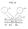
- the circular dichroism effect is a phenomenon whereby the intensity and the phase of a circularly polarized light irradiated on a recording medium and reflected therefrom exhibit anisotropy corresponding to the differing perpendicular magnetization directions of the recording medium.
- n o is the refractive index of a medium on an irradiated face of a recording medium 34
- n + is the refractive index of a recorded bit 34a wherein a magnetization direction is directed upwards with respect to the recording medium 34
- r + is the complex reflectance of the recorded bit 34a
- n - is the refractive index of a recorded bit 34b wherein a magnetization direction is directed downwards with respect to the recording medium 34
- r - is the complex reflectance of the recorded bit 34b.
- a reflected light from the recorded bit 34a becomes a left circularly polarized light L 12 and a reflected light from the recorded bit 34b becomes a left circularly polarized light L 13 having a weaker intensity than the intensity of the left circularly polarized light L 12 .
- a difference in reflected light intensity between the recorded bit 34a and the recorded bit 34b may be expressed by the following formula (1). (r + ) 2 -(r - ) 2
- the present invention provides the optical information reproducing device defined by claim 1.
- one of two linearly polarized lights emitted by a light source means is converted into a right circularly polarized light through a quarter wavelength plate means and irradiated on the magneto-optical recording medium.
- the other of the linearly polarized lights simultaneously emitted by the light source means is converted into a left circularly polarized light according to the quarter wavelength plate means and irradiated on the magneto-optical recording medium.
- the first photodetector means and the second photodetector means detect the first reflected light and the second reflected light respectively and generate the first reproduced signal and the second reproduced signal respectively.
- the first reproduced signal and the second reproduced signal have a phase difference of half a cycle and vary inversely with respect to each other. Consequently, if the first reproduced signal and the second reproduced signal are differentially amplified, a reproduced signal that varies in response to the magnetization direction of the recording medium and that has an improved SN ratio is thereby achieved.
- a first linearly polarized light emitted by a first light source means is irradiated on the magneto-optical recording medium after being converted as described earlier into (for example) the right circularly polarized light by a quarter wavelength plate means.
- a second linearly polarized light is emitted by a second light source means when the first light source means is OFF according to the switching operation of a switching means.
- the first linearly polarized light and the second linearly polarized light are thereby emitted alternately by the respective light source means.
- the second linearly polarized light is irradiated on the magneto-optical recording medium after being converted into (for example) a left circularly polarized light by the quarter wavelength plate means.
- the first reproduced signal generating means generates the first reproduced signal synchronous to the emission of the first light source means.
- the emission of the first light source means is repeatedly turned ON-OFF according to the operation of the switching means. If levels of the first reproduced signal are averaged (or integrated) over each magnetized section, then the first reproduced signal falls to a low level corresponding to the first magnetized secticn and rises to a high level corresponding to the second magnetized section.
- the second reproduced signal also averaged (or integrated) over each magnetized section, rises to a high level corresponding to the first magnetized section and falls to a low level corresponding to the second magnetized section.
- the SN ratio of the reproduced signal can be raised to a utility level by differentially amplifying the reproduced signals and thereby cancelling any noise (due to dust particles etc.) that is included in the reproduced signals based on the respective reflected light intensities.
- Figs. 1 to 3 show one embodiment of the present invention.
- Fig. 1 is an explanatory view showing essential parts of an optical reproducing device for a magneto-optical recording medium.
- Fig. 2 is an explanatory view showing the relationship between polarization directions of linearly polarized lights incident on a quarter wavelength plate.
- Fig. 3 is an explanatory view showing waveforms of reproduced signals corresponding to magnetization directions of a recording medium.
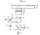
- Fig. 4 shows another embodiment of the present invention and is an explanatory view showing essential parts of an optical reproducing device for a magneto-optical recording medium.
- Figs. 5 and 6 show another embodiment of the present invention.
- Fig. 5 is an explanatory view showing essential parts of an optical reproducing device for a magneto-optical recording medium.
- Fig. 6 is a timing chart of each signal corresponding to magnetization directions of a recording medium.
- Fig. 6(a), (b) are explanatory views showing the correspondence between recorded bits and perpendicular magnetization directions.
- Fig. 6(c) is an explanatory view showing a waveform of a clock pulse.
- Fig. 6(d), (e) are explanatory views showing waveforms of high frequency signals.
- Fig. 6(f) is an explanatory view showing a waveform of reflected light intensity.
- Fig. 6(g), (h) are explanatory views showing waveforms of reproduced signals.
- Fig. 6(i), (j) are explanatory views showing waveforms of integrated reproduced signals.
- Fig. 6(k) is an explanatory view showing a waveform of a differentially amplified reproduced signal.
- Fig. 7 shows another embodiment of the present invention and is an explanatory view showing essential parts of a reproducing optical device for a magneto-optical recording medium.
- Figs. 8 to 10 show a conventional example.
- Fig. 8 is an explanatory view showing essential parts of a reproducing optical device for a magneto-optical recording medium.
- Fig. 9 is an explanatory view showing a variation in intensity of reproduced signals due to the Kerr effect.
- Fig. 10 is an explanatory view showing the circular dichroism effect of the magneto-optical recording medium.
- an optical reproducing device of the present embodiment has a semiconductor laser 1 as first light source means, a semiconductor laser 2 as second light source means, a polarization beam splitter 3, a half-mirror 4, a collimator lens 5, a quarter wavelength plate 6, a convex lens 7, a wavelength filter 10 as splitting means, a photodetector 11 as first photodetector means, and a photodetector 12 as second photodetector means.
- the semiconductor laser 1 generates a linearly polarized light whose electric field vector is perpendicular to a plane of incidence (the linearly polarized light is hereafter abbreviated as S polarized light).
- the semiconductor laser 2 generates a linearly polarized light having a different wavelength from that of the S polarized light and whose electric field vector of the P polarized light is parallel to the plane of incidence (the linearly polarized light is hereafter abbreviated as P polarized light).
- the polarization direction of the S polarized light and the polarization direction of the P polarized light are mutually orthogonal.
- the polarization beam splitter 3 completely reflects the S polarized light component of the light incident thereon and completely transmits the P polarized light component of the light incident thereon.
- the collimator lens 5 collimates the light incident thereon into a parallel pencil of light rays.
- the quarter wavelength plate 6 converts the linearly polarized light into circularly polarized light and vice versa (a prerequisite for using the quarter wavelength plate 6 is that a difference between a length of an optical path of the S polarized light component and a length of an optical path of the P polarized light component be within a range of a quarter wavelength ⁇ 20%).
- the wavelength filter 10 splits the light incident thereon according to a difference in wavelength, since the wavelength filter 10 transmits light of a specified wavelength only. In the case of the present embodiment, the wavelength filter 10 transmits light of a wavelength corresponding to the wavelength of the emission of the semiconductor laser 1.
- the semiconductor laser 1 emits a linearly polarized light L 1s as the S polarized light towards the polarization beam splitter 3
- the linearly polarized light L 1s is completely reflected from the polarization beam splitter 3 towards an optical disk 8.
- the semiconductor laser 2 emits a linearly polarized light L 2p as the P polarized light towards the polarization beam splitter 3
- the linearly polarized light L 2p is completely transmitted by the polarization beam splitter 3 and proceeds towards the optical disk 8 (consequently, both the linearly polarized light L 1s and the linearly polarized light L 2p proceed towards the optical disk 8 simultaneously).
- the linearly polarized light L 1s changes to the right circularly polarized light, since a phase of the main axis M direction component of an electric field vector of the linearly polarized light L 1s is delayed by a quarter wavelength when the linearly polarized light L 1s passes through the quarter wavelength plate 6.
- the linearly polarized light L 2p changes to a left circularly polarized light when the linearly polarized light L 2p passes through the quarter wavelength plate 6.
- an optical axis of the convex lens 7 is perpendicular with respect to a surface of a recording medium 9 provided on the optical disk 8.
- the recording medium 9 is made of, for example, a thin rare-earth transition metal alloy film and information is recorded according to a difference in magnetization direction, the magnetization direction thereof being perpendicular with respect to a surface of the recording medium 9.
- a magnetized section 9a is a section that is magnetized in a perpendicularly downward direction with respect to the surface of the recording medium 9
- a magnetized section 9b is a section that is magnetized in a perpendicularly upward direction with respect to the surface of the recording medium 9.
- the linearly polarized light L 1s emitted by the semiconductor laser 1 is completely reflected from the polarization beam splitter 3 in the direction of the optical axis of the convex lens 7. This is because the linearly polarized light L 1s serves as an S polarized light with respect to the polarization beam splitter 3.
- the linearly polarized light L 1s then is transmitted by the half mirror 4 and is collimated into the parallel pencil of light rays in the collimator lens 5. Thereafter, the linearly polarized light L 1s changes to a right circularly polarized light through the quarter wavelength plate 6, as described earlier.
- the right circularly polarized light is converged by the convex lens 7 and irradiated so as to form a beam spot on the recording medium 9 of the optical disk 8.
- the right circularly polarized light is reflected off the recording medium 9 as left circularly polarized light, as shown in the conventional example (Fig. 10).
- the reflected left circularly polarized light becomes a parallel pencil of light rays after passing through the convex lens 7 and returns to the quarter wavelength plate 6 once again as a right circularly polarized light.
- the right circularly polarized light that passes through the quarter wavelength plate 6 becomes a linearly polarized light L 1p as a P polarized light.
- the linearly polarized light L 2p that is emitted by the semiconductor laser 2 is completely transmitted by the polarization beam splitter 3 since it is a P polarized light (the wavelength of the linearly polarized light L 2p differs from the wavelength of the linearly polarized light L 1s emitted by the semiconductor laser 1). Then, the linearly polarized light L 2p changes to a left circularly polarized light according to the quarter wavelength plate 6 after being transmitted by the half mirror 4 and the collimator lens 5 in the same way as described for the linearly polarized light L 1s .
- the left circularly polarized light that is irradiated on the recording medium 9 after passing through the convex lens 7 is reflected by the recording medium 9 as a right circularly polarized light and then passes through the convex lens 7 and returns to the quarter wavelength plate 6 as a left circularly polarized light.
- the left circularly polarized light that passes through the quarter wavelength plate 6 becomes a linearly polarized light L 2s as an S polarized light.
- the linearly polarized light L 2s is reflected towards the wavelength filter 10 by the half mirror 4. Then, after being completely reflected from the wavelength filter 10, the linearly polarized light L 2s is detected by the photodetector 12.
- the present embodiment has been shown to have a configuration wherein the wavelength filter 10 receives the respective linearly polarized light converted by the quarter wavelength plate 6 from the right circularly polarized light and the left circularly polarized light reflected off the recording medium 9.
- the wavelength filter 10 may equally be arranged so that the wavelength filter 10 directly receives the right circularly polarized light and the left circularly polarized light reflected off the recording medium 9 without conversion into the respective linearly polarized light.
- a variation of a reproduced signal S 1 generated by the photodetector 11 corresponds to a variation in light intensity of the linearly polarized light L 1p that occurs when the linearly polarized light L 1p is reflected off the recording medium 9.
- a reflected light intensity of the right circularly polarized light irradiated on the magnetized section 9a (having a perpendicularly downward magnetization direction) of the recording medium 9 decreases greatly due to the circular dichroism effect, as shown in the conventional example (Fig. 10). Consequently, as shown in Fig. 3, a low level of the reproduced signal S 1 corresponds to the magnetized section 9a and a high level of the reproduced signal S 1 corresponds to the magnetized section 9b (having a perpendicularly upward magnetization direction).
- a variation of a reproduced signal S 2 generated by the photodetector 12 corresponds to a variation in light intensity of the linearly polarized light L 2s that occurs when the linearly polarized light L 2s is reflected off the recording medium 9.
- a reflected light intensity of the left circularly polarized light decreases greatly when it is irradiated on the magnetized section 9b, rather than the magnetized section 9a as happens in the case of the right circularly polarized light. Consequently, a low level of the reproduced signal S 2 corresponds to the magnetized section 9b and a high level of the reproduced signal S 2 corresponds to the magnetized section 9a.
- the reproduced signal S 1 corresponding to the magnetized section 9a and the magnetized section 9b varies inversely with respect to the reproduced signal S 2 corresponding to the magnetized section 9a and the magnetized section 9b. Consequently, the reproduced signal S 1 and the reproduced signal S 2 may be differentially amplified and thereby a reproduced signal that has a practically feasible SN ratio may be generated by a differential amplifier. Furthermore, suppose that, for example, the reproduced signal S 1 decreases from an original value by ⁇ S (Fig. 3) due to the effect of foreign matter such as dust particles adhering to the surface of the optical disk 8 and affecting reflected light intensity thereof.
- the reproduced signal S 2 also decreases by ⁇ S due to the same foreign matter, since the semiconductor laser 1 and the semiconductor laser 2 irradiate the recording medium 9 simultaneously. Consequently, ⁇ S can be cancelled by differentially amplifying the reproduced signal S 1 and the reproduced signal S 2 . Disk noise extraneous to the reproduced signal of recorded information can thereby be reduced.
- FIG. 4 Another embodiment of the present invention is described hereinbelow, referring to Fig. 4.
- components having the same function as in the aforementioned embodiment will be designated by the same references and their description will be omitted.
- the aforementioned embodiment showed a case wherein the two lights reflected off the recording medium 9 are split according to the wavelength filter 10 utilizing a difference in wavelength thereof.
- the present embodiment shows a case wherein the two lights are split according to a polarization beam splitter 3 utilizing a difference in polarization direction thereof.
- an optical reproducing device is provided with a half mirror 13 installed between a semiconductor laser 1 and the polarization beam splitter 3, and a half mirror 14 installed between a semiconductor laser 2 and the polarization beam splitter 3.
- a collimator lens 5, a quarter wavelength plate 6 and an optical disk 8 comprising a recording medium 9 are provided in line with the optical axis of a convex lens 7.
- each light that is reflected off the recording medium 9 is split by the polarization beam splitter 3, one light is reflected so as to be directed towards a photodetector 12 by the half mirror 13 and another light is reflected simultaneously so as to be directed towards a photodetector 11 by the half mirror 14.
- a linearly polarized light L 1s emitted by the semiconductor laser 1 is transmitted by the half mirror 13 and is completely reflected from the polarization beam splitter 3. Then, after successively passing through the collimator lens 5, the quarter wavelength plate 6 and the convex lens 7, the linearly polarized light L 1s is irradiated on the recording medium 9 of the optical disk 8 as a right circularly polarized light. This happens because the linearly polarized light L 1s is an S polarized light. As in the previous embodiment, a light reflected off the recording medium 9 passes through the quarter wavelength plate 6 and becomes a linearly polarized light L 1p , as a P polarized light.
- the linearly polarized light L 1s is completely transmitted by the polarization beam splitter 3. Then, the linearly polarized light L 1p is completely reflected from the half mirror 14 and is directed to the photodetector 11.
- a linearly polarized light L 2p as a P polarized light emitted by the semiconductor laser 2 also changes to a linearly polarized light L 2s as an S polarized light after passing through the quarter wavelength plate 6 and returns to the polarization beam splitter 3. Consequently, the linearly polarized light L 2s is completely reflected successively by the polarization beam splitter 3 and the half mirror 13 and is directed to the photodetector 12.
- a reflected light intensity of the right circularly polarized light varies inversely with respect to a reflected light intensity of the left circularly polarized light due to the circular dichroism effect. Consequently, disk noise can be cancelled by differentially amplifying each reproduced signal generated by the photodetector means based on each reflected light intensity.
- the optical reproducing device presents a further advantage in that the SN ratio of the reproduced signal may be raised to a utility level according to a simple optical system thereby obviating the use of an expensive conventional analyzer.
- the optical reproducing device of the present embodiment essentially comprises parts common to the configuration shown in Fig. 1, i.e., a semiconductor laser 1 and a semiconductor laser 2, a polarization beam splitter 3, a half mirror 4, a collimator lens 5, a quarter wavelength plate 6 and a convex lens 7; and, apart from these, a photodetector 15, high frequency amplifiers 16, 17, 18, 19, an oscillator 20 and an inverter 21.
- the high frequency amplifier 18 superposes a high frequency signal I 1 on a laser driving current and causes a laser light in the semiconductor laser 1 to oscillate in the multi-longitudinal mode in order to reduce laser noise that is caused when a light returns from an optical disk 8 to the semiconductor laser 1.
- the high frequency amplifier 19 superposes a high frequency signal I 2 on a laser driving current and causes a laser light in the semiconductor laser 2 to oscillate in the multi-longitudinal mode.
- the high frequency amplifier 18 and the high frequency amplifier 19 function as switching means for switching an emission of the semiconductor laser 1 and an emission of the semiconductor laser 2 at high speed since the high frequency signal I 1 and the high frequency signal I 2 are switched ON/OFF alternately.
- the high frequency amplifier 16 generates a reproduced signal S 1 based on an output of the photodetector 15 when the high frequency signal I 1 sent to the high frequency amplifier 16 is at a high level.
- the high frequency amplifier 17 generates a reproduced signal S 2 based on an output of the photodetector 15 when the high frequency signal I 2 sent to the high frequency amplifier 17 is at a high level. That is, the high frequency amplifier 16 and the photodetector 15 serve as a first reproduced signal generating means and the high frequency amplifier 17 and the photodetector 15 serve as second reproduced signal generating means.
- the oscillator 20 generates a clock pulse for the high frequency amplifier 18 and the high frequency amplifier 19.
- the inverter 21 receives the clock pulse from the oscillator 20 and supplies an inverted clock pulse to the high frequency amplifier 19.
- a magnetized section 9b that is magnetized, for example, in a perpendicularly upward direction forms a recorded bit on a recording medium 9 of the optical disk 8 (hereafter, the magnetized section 9b will be referred to as upward magnetized section 9b and a magnetized section 9a will be referred to as downward magnetized section 9a).
- the photodetector 15 may equally well receive the respective circularly polarized light reflected off the recording medium 9 directly.
- the oscillator 20 receives a high frequency superposition signal and generates a clock pulse, shown by (c) of Fig. 6, which is applied to the high frequency amplifier 18 and to the inverter 21.
- the clock pulse has a frequency of 10-100 MHz, i.e., more than 10 times the normal recorded/reproduced signal frequency.
- the high frequency amplifier 18 generates the high frequency signal I 1 as a driving current for high frequency superposition and applies the same to the semiconductor laser 1.
- the high frequency amplifier 18 also generates the high frequency signal I 1 as a reference signal which is applies to the high frequency amplifier 16.
- the high frequency signal I 1 is synchronized to the clock pulse shown by (c) of Fig. 6.
- the high frequency amplifier 19 generates the high frequency signal I 2 as a driving current for high frequency superposition and applies the same to the semiconductor laser 2.
- the high frequency amplifier 19 also generates the high frequency signal I 2 as a reference signal which is applied to the high frequency amplifier 17.
- the high frequency signal I 2 is synchronized to the inverted clock pulse generated by the inverter 21.
- the semiconductor laser 1 and the semiconductor laser 2 are alternately switched ON/OFF. That is, a linearly polarized light L 1s and a linearly polarized light L 2p are emitted alternately by the semiconductor laser 1 and the semiconductor laser 2 respectively.
- the linearly polarized light L 1s emitted by the semiconductor laser 1 becomes a linearly polarized light L 1p and is directed to the photodetector 15.
- the linearly polarized light L 1p is a P polarized light since, as described earlier, it passes through the quarter wavelength plate 6 twice.
- reflected light intensity at the upward magnetized section 9b decreases only slightly and reflected light intensity at the downward magnetized section 9a decreases greatly. This is due to the circular dichroism effect.
- the linearly polarized light L 2p (the wavelength of the linearly polarized light L 2p differs from the wavelength of the linearly polarized light L 1s emitted by the semiconductor laser 1) emitted by the semiconductor laser 2 becomes a linearly polarized light L 2s and is directed to the photodetector 15.
- the linearly polarized light L 2s is in this case an S polarized light since it also passes through the quarter wavelength plate 6 twice.
- reflected light intensity at the upward magnetized section 9b decreases greatly and reflected light intensity at the downward magnetized section 9a decreases only slightly. This is due to the circular dichroism effect and is the converse of the case where the linearly polarized light L 1s is emitted.
- the high frequency signal I 1 that switches the semiconductor laser 1 to ON is a high frequency signal I 1a (shown by (d) of Fig. 6).
- a reflected light intensity I R1a of the linearly polarized light L 1p becomes relatively small because of a decreasing action of the downward magnetized section 9a.
- the linearly polarized light L 1p is directed to the photodetector 15 after being reflected off the downward magnetized section 9a.
- the high frequency signal I 2 that switches the semiconductor laser 2 to ON is a high frequency signal I 2a (shown by (e) of Fig. 6).
- a reflected light intensity I R2a of the linearly polarized light L 2s becomes relatively large for the same reason as given above.
- the linearly polarized light L 2s is directed to the photodetector 15 after being reflected off the downward magnetized section 9a. Comparing (e) and (f) of Fig. 6 makes it clear that a rising edge of a reflected light intensity I R of a light reflected off the downward magnetized section 9a is synchronous to a rising edge of the high frequency signal I 2 .
- the high frequency signal I 1 that switches the semiconductor laser 1 to ON is a high frequency signal I 1b (shown by (d) of Fig. 6).
- a reflected light intensity I R1b of the linearly polarized light L 1p becomes relatively large.
- the linearly polarized light L 1p is directed to the photodetector 15 after being reflected off the upward magnetized section 9b.
- the high frequency signal I 2 that switches the semiconductor laser 2 to ON is a high frequency signal I 2b (shown by (e) of Fig. 6).
- a reflected light intensity I R2b of the linearly polarized light L 2s becomes relatively small because of a decreasing action of the upward magnetized section 9b.
- the linearly polarized light L 2s is directed to the photodetector 15 after being reflected off the upward magnetized section 9b. Comparing (d) and (f) of Fig. 6 makes it clear that a rising edge of a reflected light intensity I R of a light reflected off the upward magnetized section 9b is synchronous to a rising edge of the high frequency signal I 1 .
- the reflected light intensity I R becomes symmetrical around a vicinity where the upward magnetized section 9a adjoins the downward magnetized section 9b. That is, there is a phase difference of half a cycle between a temporal variation of the reflected light intensity I R at the upward magnetized section 9b and a temporal variation of the reflected light intensity I R at the downward magnetized section 9a.
- the high level reproduced signal S 1b is based on the reflected light intensity I R1b (of the linearly polarized light L 1P ) that is received by the photodetector 15. Naturally, the reproduced signal S 1 becomes 0 when the high frequency signal I 1 is OFF.
- an integrated reproduced signal T 1 is achieved by processing the reproduced signal S 1 according to integrating means (not shown) such as an integrating circuit.
- the integrated reproduced signal T 1 is at a high level corresponding with the upward magnetized section 9b and at a low level corresponding with the downward magnetized section 9a.
- the low level reproduced signal S 2b is based on the reflected light intensity I R2b (of the linearly polarized light L 2s ) that is received by the photodetector 15. Naturally, the reproduced signal S 2 becomes 0 when the high frequency signal I 2 is OFF.
- an integrated reproduced signal T 2 is achieved by processing the reproduced signal S 2 according to the integrating circuit.
- the integrated reproduced signal T 1 and the integrated reproduced signal T 2 vary inversely with respect to each other since there is a phase difference of half a cycle between them.
- the integrated reproduced signal T 2 is thus at a low level in correspondence with the upward magnetized section 9b and at a high level in correspondence with the downward magnetized section 9a.
- FIG. 7 Another embodiment of the present invention is described hereinbelow, referring to Fig. 7.
- components having the same function as in the aforementioned embodiment will be designated by the same references and their description will be omitted.
- a case is shown wherein the reproduced signals are based on the two reflected light intensities of the light reflected off the recording medium 9 and the reproduced signals are split according to switching operations of the high frequency amplifier 16 and the high frequency amplifier 17.
- a case is shown wherein a polarization beam splitter 3 is used as splitting means. In this case, two reflected lights are split according to a difference in direction of respective polarized lights.
- a reproducing optical device of the present embodiment in addition to a configuration as shown in Fig. 4, is provided with a high frequency amplifier 18 that sends a high frequency signal I 1 to a semiconductor laser 1, a high frequency amplifier 19 that sends a high frequency signal I 2 to a semiconductor laser 2, an oscillator 20 that generates a clock pulse and an inverter 21 that supplies an inverted clock pulse to the high frequency amplifier 19.
- a linearly polarized light L 1S emitted by a semiconductor laser 1 becomes a linearly polarized light L 1p as a P polarized light after passing through a quarter wavelength plate 6 twice.
- the linearly polarized light L 1p is directed to a photodetector 11 after being completely transmitted by the polarization beam splitter 3 and then being completely reflected from the half mirror 14.
- a linearly polarized light L 2p emitted by a stylor laser 2 returns to the polarization beam splitter 3 as a linearly polarized light L 2s .
- the linearly polarized light L 2s is an S polarized light.
- the linearly polarized light L 2s is directed to a photodetector 12 after being completely reflected in succession by both the polarization beam splitter 3 and the half mirror 13.
- a reproduced signal S 1 that is generated by the photodetector 11 and a reproduced signal S 2 that is generated by the photodetector 12 are split and generated without necessitating the switching operation of the high frequency amplifier 16 and the high frequency amplifier 17 as mentioned earlier.
- a rising edge of the reproduced signal S 1 is synchronous to a rising edge of the high frequency signal I 1 .
- a variation in intensity of the reproduced signal S 1 corresponds to a downward magnetized section 9a and an upward magnetized section 9b as has been previously described referring to Fig. 6.
- a rising edge of the reproduced signal S 2 is synchronous to a rising edge of the high frequency signal I 2 .
- a variation in intensity of the reproduced signal S 2 corresponds to the downward magnetized section 9a and the upward magnetized section 9b as has been previously described referring to Fig. 6.
- An explanation of a reproduced signal ⁇ T achieved by differential amplification is as previously noted and is therefore omitted.
- each reflected light intensity thereof varies inversely with respect to the other in response to the magnetization direction of the recording medium. This is due to the circular dichroism effect. Accordingly, disk noise can be cancelled by differentially amplifying each reproduced signal based on each reflected light intensity and generated by photodetector means. (Further, in the case where the right circularly polarized light and the left circularly polarized light are switched at high speed during irradiation on the recording medium, each signal is first integrated and then differentiated).
- the optical reproducing device for a magneto-optical recording medium has an advantage in that a reproduced signal having a utility level SN ratio may be achieved according to a simple optical system and without necessitating an expensive analyzer.
Description
- The present invention relates to an optical reproducing device for a magneto-optical recording medium, and more specifically to an optical reproducing device that generates a reproduced signal by differentially amplifying magneto-optical signals detected using the circular dichroism effect of magnetic substances.
- An optical disk utilizing a thin rare-earth transition metal alloy film as a recording medium is in a practical application stage as a digital memory. When information that is recorded in the optical disk is to be reproduced, usually a linearly polarized light generated by a semiconductor laser is irradiated on a recording medium. After the linearly polarized light is reflected off the recording medium, an amount of rotation of a polarization plane thereof is detected by an analyzer and converted into light intensity.
- The principles of a reproducing method as described above, wherein the so-called Kerr effect is used, are described hereinbelow.
- When the linearly polarized light generated by the semiconductor laser is reflected off the recording medium, the polarization plane thereof is rotated to the right or the left corresponding to a differing perpendicular magnetization direction of the recording medium. A reflected light R11 (shown in Fig. 8) that is reflected off the recording medium includes binary information recorded in the recording medium by transposing the binary information into a rotational direction of the polarization plane. The reflected light R11 is directed to an
analyzer 31 and is split into a detected light D11 and a detected light D12 in theanalyzer 31 according to a difference in the rotational direction of the polarization plane of the light R11. A photodetector 32 and aphotodetector 33 convert the detected light D11 and the detected light D12 respectively into electric signals, thereby generating a reproduced signal S11 and a reproduced signal S12 respectively. - Suppose that a specified perpendicular magnetization direction of the recording medium is designated by (+) and an opposite perpendicular magnetization direction thereof is designated by (-). Also, suppose that γ is an incident light vector, α is a reflected light vector reflected off a recorded bit magnetized in the (+) direction, and β is a reflected light vector reflected off a recorded bit magnetized in the (-) direction. As shown in Fig. 9, if the polarization plane of the reflected light vector α rotates, for example, by Kerr rotative angle + θk with respect to the incident light vector γ, the polarization plane of the reflected light vector β will on the contrary rotate by Kerr rotative angle - θk with respect to the incident light vector γ.
- Since a polarization direction X and a polarization direction Y of the
analyzer 31 are mutually orthogonal, intensities of the reflected light vector α and the reflected light vector β are respectively split into X components and Y components thereof and are then detected. Thephotodetector 32 generates the reproduced signal S11. Here, a high level of the reproduced signal S11 corresponds to an X component βx of the reflected light vector β and a low level of the reproduced signal S11 corresponds to an X component αx of the reflected light vector α. That is, the high level of the reproduced signal S11 corresponds to the recorded bit magnetized in the (-) direction. - On the other hand, when the reproduced signal S11 is at the low level corresponding to the X component αx of the reflected light vector α, the
photodetector 33 generates the reproduced signal S12 that is at a high level corresponding to a Y component αy of the reflected light vector α. Further, when the reproduced signal S11 is at the high level corresponding to the X component βx of the reflected light vector β, thephotodetector 33 generates the reproduced signal S12 that is at a low level corresponding to a Y component βy of the reflected light vector β. The high level of the reproduced signal S12 corresponds to the recorded bit magnetized in the (+) direction. - As described above, the high level of the reproduced signal S11 generated by the
photodetector 32 corresponds to the recorded bit magnetized in the (-) direction and the high level of the reproduced signal S12 generated by thephotodetector 33 corresponds to the recorded bit magnetized in the (+) direction. The reproduced signal S11 and the reproduced signal S12 have a phase difference of half a cycle, and vary inversely with respect to each other. Furthermore, the reproduced signal S11 and the reproduced signal S12 achieved in this way largely exclude disk noise since they are not affected by dust particles or the like attached to the disk surface. This is because the reproduced signal S11 and the reproduced signal S12 are based on the rotation of the polarization plane of each reflected light. Moreover, the SN ratio may be further improved by supplying the reproduced signal S11 and the reproduced signal S12 to a differential amplifier and performing information reproduction based on an output signal of the differential amplifier. - However, the reproduction method based on the Kerr effect described above and normally used for performing magneto-optical recordings has a problem in that a high degree of accuracy is necessary for setting the
analyzer 31. The method has a further disadvantage of causing a rise in cost of the reproducing device. - A method of reducing the cost of the reproducing device by not using an analyzer and thereby simplifying the reproducing optical device has already been developed theoretically. This method uses the so-called circular dichroism effect. The circular dichroism effect is a phenomenon whereby the intensity and the phase of a circularly polarized light irradiated on a recording medium and reflected therefrom exhibit anisotropy corresponding to the differing perpendicular magnetization directions of the recording medium.
- As shown in Fig. 10, suppose that no is the refractive index of a medium on an irradiated face of a
recording medium 34, n+ is the refractive index of a recordedbit 34a wherein a magnetization direction is directed upwards with respect to therecording medium 34, r+ is the complex reflectance of the recordedbit 34a, n- is the refractive index of a recordedbit 34b wherein a magnetization direction is directed downwards with respect to therecording medium 34 and r- is the complex reflectance of the recordedbit 34b. For example, suppose that there is a right circularly polarized light L11 irradiated on therecording medium 34 and that an electric field vector of the right circularly polarized light L11 rotates clockwise facing a light source. A reflected light from the recordedbit 34a becomes a left circularly polarized light L12 and a reflected light from the recordedbit 34b becomes a left circularly polarized light L13 having a weaker intensity than the intensity of the left circularly polarized light L12. A difference in reflected light intensity between the recordedbit 34a and the recordedbit 34b may be expressed by the following formula (1).
- (If a left circularly polarized light is irradiated on the
recording medium 34, the reflected light becomes a right circularly polarized light and the above relationship between the reflected light intensities corresponding to the recordedbit 34a and the recordedbit 34b is reversed). Further, r+ and r- may be expressed in terms of no, n+ and n- as follows.

- However, in a reproduction method using the circular dichroism effect, noise comes to be included in the reproduced signal since an attempt is made to detect the magnetization direction of the recording medium by transposing it into a difference in reflected light intensity. This is because foreign matter such as dust particles that adhere to the surface of the optical disk affect the reflected light intensity. As a result, there is a greater tendency for signal quality to deteriorate when a reproduction method using the circular dichroism effect is employed than when a conventional reproduction method using the Kerr effect is employed.
- It is an object of the present invention to provide an optical reproducing device for a magneto-optical recording medium that achieves a superior quality reproduced signal using a simple optical system, by employing a configuration wherein information is reproduced from a magneto-optical recording medium using the circular dichroism effect and not the Kerr effect.
- In one aspect, the present invention provides the optical information reproducing device defined by
claim 1. - According to one embodiment of the device of
claim 1, one of two linearly polarized lights emitted by a light source means is converted into a right circularly polarized light through a quarter wavelength plate means and irradiated on the magneto-optical recording medium. The other of the linearly polarized lights simultaneously emitted by the light source means is converted into a left circularly polarized light according to the quarter wavelength plate means and irradiated on the magneto-optical recording medium. - When the right circularly polarized light is irradiated on a first magnetized section that is magnetized in a perpendicularly downward direction with respect to the surface of the magneto-optical recording medium, an intensity of the first reflected light greatly decreases. This is because the magneto-optical recording medium made of, for example, a thin rare-earth transition metal alloy film has the property of circular dichroism. On the other hand, when the left circularly polarized light is irradiated on the first magnetized section, an intensity of the second reflected light decreases only slightly. Further, when the right circularly polarized light is irradiated on a second magnetized section that is magnetized in a perpendicularly upward direction, the intensity of the first reflected light decreases only slightly. On the other hand, when the left circularly polarized light is irradiated on the second magnetized section, the intensity of the second reflected light greatly decreases.
- As a result, when the right circularly polarized light and the left circularly polarized light are respectively irradiated on the magneto-optical recording medium, a phase difference of half a cycle develops between them and they vary inversely with respect to each other. The first photodetector means and the second photodetector means detect the first reflected light and the second reflected light respectively and generate the first reproduced signal and the second reproduced signal respectively. The first reproduced signal and the second reproduced signal have a phase difference of half a cycle and vary inversely with respect to each other. Consequently, if the first reproduced signal and the second reproduced signal are differentially amplified, a reproduced signal that varies in response to the magnetization direction of the recording medium and that has an improved SN ratio is thereby achieved.
- According to another embodiment of the device of
claim 1, a first linearly polarized light emitted by a first light source means is irradiated on the magneto-optical recording medium after being converted as described earlier into (for example) the right circularly polarized light by a quarter wavelength plate means. A second linearly polarized light is emitted by a second light source means when the first light source means is OFF according to the switching operation of a switching means. The first linearly polarized light and the second linearly polarized light are thereby emitted alternately by the respective light source means. The second linearly polarized light is irradiated on the magneto-optical recording medium after being converted into (for example) a left circularly polarized light by the quarter wavelength plate means. - As described above, when the right circularly polarized light is irradiated on the first magnetized section, the first reflected light thereof greatly decreases. When the right circularly polarized light is irradiated on the second magnetized section, the first reflected light intensity thereof decreases only slightly. The first reproduced signal generating means generates the first reproduced signal synchronous to the emission of the first light source means. The emission of the first light source means is repeatedly turned ON-OFF according to the operation of the switching means. If levels of the first reproduced signal are averaged (or integrated) over each magnetized section, then the first reproduced signal falls to a low level corresponding to the first magnetized secticn and rises to a high level corresponding to the second magnetized section. On the other hand, the second reproduced signal, also averaged (or integrated) over each magnetized section, rises to a high level corresponding to the first magnetized section and falls to a low level corresponding to the second magnetized section.
- Consequently, since, in the device of this embodiment, an integrated signal of the first reproduced signal and an integrated signal of the second reproduced signal are differentially amplified, a reproduced signal that varies corresponding to the magnetization direction of the recording medium is achieved. The SN ratio is thereby improved.
- As described above, the SN ratio of the reproduced signal can be raised to a utility level by differentially amplifying the reproduced signals and thereby cancelling any noise (due to dust particles etc.) that is included in the reproduced signals based on the respective reflected light intensities.
- Figs. 1 to 3 show one embodiment of the present invention.
- Fig. 1 is an explanatory view showing essential parts of an optical reproducing device for a magneto-optical recording medium.
- Fig. 2 is an explanatory view showing the relationship between polarization directions of linearly polarized lights incident on a quarter wavelength plate.
- Fig. 3 is an explanatory view showing waveforms of reproduced signals corresponding to magnetization directions of a recording medium.
- Fig. 4 shows another embodiment of the present invention and is an explanatory view showing essential parts of an optical reproducing device for a magneto-optical recording medium.
- Figs. 5 and 6 show another embodiment of the present invention.
- Fig. 5 is an explanatory view showing essential parts of an optical reproducing device for a magneto-optical recording medium.
- Fig. 6 is a timing chart of each signal corresponding to magnetization directions of a recording medium.
- Fig. 6(a), (b) are explanatory views showing the correspondence between recorded bits and perpendicular magnetization directions.
- Fig. 6(c) is an explanatory view showing a waveform of a clock pulse.
- Fig. 6(d), (e) are explanatory views showing waveforms of high frequency signals.
- Fig. 6(f) is an explanatory view showing a waveform of reflected light intensity.
- Fig. 6(g), (h) are explanatory views showing waveforms of reproduced signals.
- Fig. 6(i), (j) are explanatory views showing waveforms of integrated reproduced signals.
- Fig. 6(k) is an explanatory view showing a waveform of a differentially amplified reproduced signal.
- Fig. 7 shows another embodiment of the present invention and is an explanatory view showing essential parts of a reproducing optical device for a magneto-optical recording medium.
- Figs. 8 to 10 show a conventional example.
- Fig. 8 is an explanatory view showing essential parts of a reproducing optical device for a magneto-optical recording medium.
- Fig. 9 is an explanatory view showing a variation in intensity of reproduced signals due to the Kerr effect.
- Fig. 10 is an explanatory view showing the circular dichroism effect of the magneto-optical recording medium.
- One embodiment of the present invention is described hereinbelow, referring to Figs. 1 to 3.
- As shown schematically in Fig. 1, an optical reproducing device of the present embodiment has a
semiconductor laser 1 as first light source means, asemiconductor laser 2 as second light source means, apolarization beam splitter 3, a half-mirror 4, acollimator lens 5, aquarter wavelength plate 6, aconvex lens 7, awavelength filter 10 as splitting means, aphotodetector 11 as first photodetector means, and aphotodetector 12 as second photodetector means. Thesemiconductor laser 1 generates a linearly polarized light whose electric field vector is perpendicular to a plane of incidence (the linearly polarized light is hereafter abbreviated as S polarized light). Thesemiconductor laser 2 generates a linearly polarized light having a different wavelength from that of the S polarized light and whose electric field vector of the P polarized light is parallel to the plane of incidence (the linearly polarized light is hereafter abbreviated as P polarized light). The polarization direction of the S polarized light and the polarization direction of the P polarized light are mutually orthogonal. Thepolarization beam splitter 3 completely reflects the S polarized light component of the light incident thereon and completely transmits the P polarized light component of the light incident thereon. Thecollimator lens 5 collimates the light incident thereon into a parallel pencil of light rays. Thequarter wavelength plate 6 converts the linearly polarized light into circularly polarized light and vice versa (a prerequisite for using thequarter wavelength plate 6 is that a difference between a length of an optical path of the S polarized light component and a length of an optical path of the P polarized light component be within a range of a quarter wavelength ± 20%). Thewavelength filter 10 splits the light incident thereon according to a difference in wavelength, since thewavelength filter 10 transmits light of a specified wavelength only. In the case of the present embodiment, thewavelength filter 10 transmits light of a wavelength corresponding to the wavelength of the emission of thesemiconductor laser 1. - If, for example, the
semiconductor laser 1 emits a linearly polarized light L1s as the S polarized light towards thepolarization beam splitter 3, the linearly polarized light L1s is completely reflected from thepolarization beam splitter 3 towards anoptical disk 8. On the other hand, if thesemiconductor laser 2 emits a linearly polarized light L2p as the P polarized light towards thepolarization beam splitter 3, the linearly polarized light L2p is completely transmitted by thepolarization beam splitter 3 and proceeds towards the optical disk 8 (consequently, both the linearly polarized light L1s and the linearly polarized light L2p proceed towards theoptical disk 8 simultaneously). - As shown in Fig. 2, the configuration of the
quarter wavelength plate 6 is such that a polarization direction Ns of the linearly polarized light L1s incident on thequarter wavelength plate 6 rotates anti-clockwise to an angle of θ=45° with respect to a main axis M of thequarter wavelength plate 6. Further, a polarization direction Np of the linearly polarized light L2p incident on thequarter wavelength plate 6 rotates clockwise to an angle of θ=45° with respect to the main axis M of thequarter wavelength plate 6. A phase of the main axis M direction component of an electric field vector of the light that is incident on thequarter wavelength plate 6 is delayed by a quarter wavelength. Consequently, the linearly polarized light L1s changes to the right circularly polarized light, since a phase of the main axis M direction component of an electric field vector of the linearly polarized light L1s is delayed by a quarter wavelength when the linearly polarized light L1s passes through thequarter wavelength plate 6. On the other hand, the linearly polarized light L2p changes to a left circularly polarized light when the linearly polarized light L2p passes through thequarter wavelength plate 6. - As shown in Fig. 1, an optical axis of the
convex lens 7 is perpendicular with respect to a surface of arecording medium 9 provided on theoptical disk 8. Therecording medium 9 is made of, for example, a thin rare-earth transition metal alloy film and information is recorded according to a difference in magnetization direction, the magnetization direction thereof being perpendicular with respect to a surface of therecording medium 9. As shown in Fig. 3, amagnetized section 9a is a section that is magnetized in a perpendicularly downward direction with respect to the surface of therecording medium 9, and amagnetized section 9b is a section that is magnetized in a perpendicularly upward direction with respect to the surface of therecording medium 9. - With the above arrangement, the linearly polarized light L1s emitted by the
semiconductor laser 1 is completely reflected from thepolarization beam splitter 3 in the direction of the optical axis of theconvex lens 7. This is because the linearly polarized light L1s serves as an S polarized light with respect to thepolarization beam splitter 3. The linearly polarized light L1s then is transmitted by the half mirror 4 and is collimated into the parallel pencil of light rays in thecollimator lens 5. Thereafter, the linearly polarized light L1s changes to a right circularly polarized light through thequarter wavelength plate 6, as described earlier. The right circularly polarized light is converged by theconvex lens 7 and irradiated so as to form a beam spot on therecording medium 9 of theoptical disk 8. The right circularly polarized light is reflected off therecording medium 9 as left circularly polarized light, as shown in the conventional example (Fig. 10). Then, the reflected left circularly polarized light becomes a parallel pencil of light rays after passing through theconvex lens 7 and returns to thequarter wavelength plate 6 once again as a right circularly polarized light. The right circularly polarized light that passes through thequarter wavelength plate 6 becomes a linearly polarized light L1p as a P polarized light. This happens because a phase of the main axis M direction component of an electric field vector of the right circularly polarized light is delayed by a quarter wavelength. After passing through thecollimator lens 5, the linearly polarized light L1p is reflected towards thewavelength filter 10 by the half mirror 4. Then, after being completely transmitted by thewavelength filter 10, the linearly polarized light L1p is detected by thephotodetector 11. - On the other hand, the linearly polarized light L2p that is emitted by the
semiconductor laser 2 is completely transmitted by thepolarization beam splitter 3 since it is a P polarized light (the wavelength of the linearly polarized light L2p differs from the wavelength of the linearly polarized light L1s emitted by the semiconductor laser 1). Then, the linearly polarized light L2p changes to a left circularly polarized light according to thequarter wavelength plate 6 after being transmitted by the half mirror 4 and thecollimator lens 5 in the same way as described for the linearly polarized light L1s. The left circularly polarized light that is irradiated on therecording medium 9 after passing through theconvex lens 7 is reflected by therecording medium 9 as a right circularly polarized light and then passes through theconvex lens 7 and returns to thequarter wavelength plate 6 as a left circularly polarized light. The left circularly polarized light that passes through thequarter wavelength plate 6 becomes a linearly polarized light L2s as an S polarized light. After passing through thecollimator lens 5, the linearly polarized light L2s is reflected towards thewavelength filter 10 by the half mirror 4. Then, after being completely reflected from thewavelength filter 10, the linearly polarized light L2s is detected by thephotodetector 12. - Further, the present embodiment has been shown to have a configuration wherein the
wavelength filter 10 receives the respective linearly polarized light converted by thequarter wavelength plate 6 from the right circularly polarized light and the left circularly polarized light reflected off therecording medium 9. However, it may equally be arranged so that thewavelength filter 10 directly receives the right circularly polarized light and the left circularly polarized light reflected off therecording medium 9 without conversion into the respective linearly polarized light. - A variation of a reproduced signal S1 generated by the
photodetector 11 corresponds to a variation in light intensity of the linearly polarized light L1p that occurs when the linearly polarized light L1p is reflected off therecording medium 9. A reflected light intensity of the right circularly polarized light irradiated on themagnetized section 9a (having a perpendicularly downward magnetization direction) of therecording medium 9 decreases greatly due to the circular dichroism effect, as shown in the conventional example (Fig. 10). Consequently, as shown in Fig. 3, a low level of the reproduced signal S1 corresponds to themagnetized section 9a and a high level of the reproduced signal S1 corresponds to themagnetized section 9b (having a perpendicularly upward magnetization direction). - On the other hand, a variation of a reproduced signal S2 generated by the
photodetector 12 corresponds to a variation in light intensity of the linearly polarized light L2s that occurs when the linearly polarized light L2s is reflected off therecording medium 9. A reflected light intensity of the left circularly polarized light decreases greatly when it is irradiated on themagnetized section 9b, rather than themagnetized section 9a as happens in the case of the right circularly polarized light. Consequently, a low level of the reproduced signal S2 corresponds to themagnetized section 9b and a high level of the reproduced signal S2 corresponds to themagnetized section 9a. - As a result, the reproduced signal S1 corresponding to the
magnetized section 9a and themagnetized section 9b varies inversely with respect to the reproduced signal S2 corresponding to themagnetized section 9a and themagnetized section 9b. Consequently, the reproduced signal S1 and the reproduced signal S2 may be differentially amplified and thereby a reproduced signal that has a practically feasible SN ratio may be generated by a differential amplifier. Furthermore, suppose that, for example, the reproduced signal S1 decreases from an original value by ΔS (Fig. 3) due to the effect of foreign matter such as dust particles adhering to the surface of theoptical disk 8 and affecting reflected light intensity thereof. Here, the reproduced signal S2 also decreases by ΔS due to the same foreign matter, since thesemiconductor laser 1 and thesemiconductor laser 2 irradiate therecording medium 9 simultaneously. Consequently, ΔS can be cancelled by differentially amplifying the reproduced signal S1 and the reproduced signal S2. Disk noise extraneous to the reproduced signal of recorded information can thereby be reduced. - Another embodiment of the present invention is described hereinbelow, referring to Fig. 4. For the sake of convenience, components having the same function as in the aforementioned embodiment will be designated by the same references and their description will be omitted.
- The aforementioned embodiment showed a case wherein the two lights reflected off the
recording medium 9 are split according to thewavelength filter 10 utilizing a difference in wavelength thereof. The present embodiment shows a case wherein the two lights are split according to apolarization beam splitter 3 utilizing a difference in polarization direction thereof. - As shown in Fig. 4, an optical reproducing device according to the present embodiment is provided with a
half mirror 13 installed between asemiconductor laser 1 and thepolarization beam splitter 3, and ahalf mirror 14 installed between asemiconductor laser 2 and thepolarization beam splitter 3. In the same way as shown in Fig. 3, acollimator lens 5, aquarter wavelength plate 6 and anoptical disk 8 comprising arecording medium 9 are provided in line with the optical axis of aconvex lens 7. Further, as will be described later, after each light that is reflected off therecording medium 9 is split by thepolarization beam splitter 3, one light is reflected so as to be directed towards aphotodetector 12 by thehalf mirror 13 and another light is reflected simultaneously so as to be directed towards aphotodetector 11 by thehalf mirror 14. - With the above arrangement, a linearly polarized light L1s emitted by the
semiconductor laser 1 is transmitted by thehalf mirror 13 and is completely reflected from thepolarization beam splitter 3. Then, after successively passing through thecollimator lens 5, thequarter wavelength plate 6 and theconvex lens 7, the linearly polarized light L1s is irradiated on therecording medium 9 of theoptical disk 8 as a right circularly polarized light. This happens because the linearly polarized light L1s is an S polarized light. As in the previous embodiment, a light reflected off therecording medium 9 passes through thequarter wavelength plate 6 and becomes a linearly polarized light L1p, as a P polarized light. Since it is a P polarized light, the linearly polarized light L1s is completely transmitted by thepolarization beam splitter 3. Then, the linearly polarized light L1p is completely reflected from thehalf mirror 14 and is directed to thephotodetector 11. - As in the previous embodiment, a linearly polarized light L2p as a P polarized light emitted by the
semiconductor laser 2 also changes to a linearly polarized light L2s as an S polarized light after passing through thequarter wavelength plate 6 and returns to thepolarization beam splitter 3. Consequently, the linearly polarized light L2s is completely reflected successively by thepolarization beam splitter 3 and thehalf mirror 13 and is directed to thephotodetector 12. - Here, an explanation of a reproduced signal achieved by differential amplification of a reproduced signal S1 generated by the
photodetector 11 and a reproduced signal S2 generated by thephotodetector 12 is the same as that for the previous embodiment and is therefore omitted. - As described earlier, in a case where a right circularly polarized light and a left circularly polarized light are simultaneously directed towards the recording medium, a reflected light intensity of the right circularly polarized light varies inversely with respect to a reflected light intensity of the left circularly polarized light due to the circular dichroism effect. Consequently, disk noise can be cancelled by differentially amplifying each reproduced signal generated by the photodetector means based on each reflected light intensity. The optical reproducing device according to the present embodiment presents a further advantage in that the SN ratio of the reproduced signal may be raised to a utility level according to a simple optical system thereby obviating the use of an expensive conventional analyzer.
- Another embodiment of the present invention is described hereinbelow, referring to Figs. 5 to 7. For the sake of convenience, components having the same function as in the aforementioned embodiment will be designated by the same references and their description will be omitted.
- As shown schematically in Fig. 5, the optical reproducing device of the present embodiment essentially comprises parts common to the configuration shown in Fig. 1, i.e., a
semiconductor laser 1 and asemiconductor laser 2, apolarization beam splitter 3, a half mirror 4, acollimator lens 5, aquarter wavelength plate 6 and aconvex lens 7; and, apart from these, aphotodetector 15,high frequency amplifiers oscillator 20 and aninverter 21. - The
high frequency amplifier 18 superposes a high frequency signal I1 on a laser driving current and causes a laser light in thesemiconductor laser 1 to oscillate in the multi-longitudinal mode in order to reduce laser noise that is caused when a light returns from anoptical disk 8 to thesemiconductor laser 1. Similarly, thehigh frequency amplifier 19 superposes a high frequency signal I2 on a laser driving current and causes a laser light in thesemiconductor laser 2 to oscillate in the multi-longitudinal mode. Thehigh frequency amplifier 18 and thehigh frequency amplifier 19 function as switching means for switching an emission of thesemiconductor laser 1 and an emission of thesemiconductor laser 2 at high speed since the high frequency signal I1 and the high frequency signal I2 are switched ON/OFF alternately. Thehigh frequency amplifier 16 generates a reproduced signal S1 based on an output of thephotodetector 15 when the high frequency signal I1 sent to thehigh frequency amplifier 16 is at a high level. The high frequency amplifier 17 generates a reproduced signal S2 based on an output of thephotodetector 15 when the high frequency signal I2 sent to the high frequency amplifier 17 is at a high level. That is, thehigh frequency amplifier 16 and thephotodetector 15 serve as a first reproduced signal generating means and the high frequency amplifier 17 and thephotodetector 15 serve as second reproduced signal generating means. Theoscillator 20 generates a clock pulse for thehigh frequency amplifier 18 and thehigh frequency amplifier 19. Theinverter 21 receives the clock pulse from theoscillator 20 and supplies an inverted clock pulse to thehigh frequency amplifier 19. - As shown in (a) and (b) of Fig. 6, a
magnetized section 9b that is magnetized, for example, in a perpendicularly upward direction forms a recorded bit on arecording medium 9 of the optical disk 8 (hereafter, themagnetized section 9b will be referred to as upwardmagnetized section 9b and amagnetized section 9a will be referred to as downwardmagnetized section 9a). Further, although in the present embodiment a case is described wherein thephotodetector 15 receives each linearly polarized light that has been respectively converted through thequarter wavelength plate 6 from each circularly polarized light reflected off therecording medium 9, thephotodetector 15 may equally well receive the respective circularly polarized light reflected off therecording medium 9 directly. - The following description refers to Fig. 5 where necessary. The
oscillator 20 receives a high frequency superposition signal and generates a clock pulse, shown by (c) of Fig. 6, which is applied to thehigh frequency amplifier 18 and to theinverter 21. The clock pulse has a frequency of 10-100 MHz, i.e., more than 10 times the normal recorded/reproduced signal frequency. Thehigh frequency amplifier 18 generates the high frequency signal I1 as a driving current for high frequency superposition and applies the same to thesemiconductor laser 1. Thehigh frequency amplifier 18 also generates the high frequency signal I1 as a reference signal which is applies to thehigh frequency amplifier 16. As shown by (d) of Fig. 6, the high frequency signal I1 is synchronized to the clock pulse shown by (c) of Fig. 6. Thehigh frequency amplifier 19 generates the high frequency signal I2 as a driving current for high frequency superposition and applies the same to thesemiconductor laser 2. Thehigh frequency amplifier 19 also generates the high frequency signal I2 as a reference signal which is applied to the high frequency amplifier 17. As shown by (e) of Fig. 6, the high frequency signal I2 is synchronized to the inverted clock pulse generated by theinverter 21. In this way, thesemiconductor laser 1 and thesemiconductor laser 2 are alternately switched ON/OFF. That is, a linearly polarized light L1s and a linearly polarized light L2p are emitted alternately by thesemiconductor laser 1 and thesemiconductor laser 2 respectively. - With the above arrangement, the linearly polarized light L1s emitted by the
semiconductor laser 1 becomes a linearly polarized light L1p and is directed to thephotodetector 15. The linearly polarized light L1p is a P polarized light since, as described earlier, it passes through thequarter wavelength plate 6 twice. Here, reflected light intensity at the upwardmagnetized section 9b decreases only slightly and reflected light intensity at the downwardmagnetized section 9a decreases greatly. This is due to the circular dichroism effect. - Similarly, when the
semiconductor laser 1 is OFF, the linearly polarized light L2p (the wavelength of the linearly polarized light L2p differs from the wavelength of the linearly polarized light L1s emitted by the semiconductor laser 1) emitted by thesemiconductor laser 2 becomes a linearly polarized light L2s and is directed to thephotodetector 15. However, the linearly polarized light L2s is in this case an S polarized light since it also passes through thequarter wavelength plate 6 twice. Here, reflected light intensity at the upwardmagnetized section 9b decreases greatly and reflected light intensity at the downwardmagnetized section 9a decreases only slightly. This is due to the circular dichroism effect and is the converse of the case where the linearly polarized light L1s is emitted. - A description follows hereinbelow of the variation in intensity of the reflected lights (the linearly polarized light L1p and the linearly polarized light L2s) directed to the
photodetector 15. In the case when, for example, thesemiconductor laser 1 emits the linearly polarized light L1s with respect to the downwardmagnetized section 9a, the high frequency signal I1 that switches thesemiconductor laser 1 to ON is a high frequency signal I1a (shown by (d) of Fig. 6). As shown by (f) of Fig. 6, a reflected light intensity IR1a of the linearly polarized light L1p becomes relatively small because of a decreasing action of the downwardmagnetized section 9a. Here, the linearly polarized light L1p is directed to thephotodetector 15 after being reflected off the downwardmagnetized section 9a. On the other hand, when thesemiconductor laser 1 is OFF and thesemiconductor laser 2 emits the linearly polarized light L2p with respect to the downwardmagnetized section 9a, the high frequency signal I2 that switches thesemiconductor laser 2 to ON is a high frequency signal I2a (shown by (e) of Fig. 6). As shown by (f) of Fig. 6, a reflected light intensity IR2a of the linearly polarized light L2s becomes relatively large for the same reason as given above. Here, the linearly polarized light L2s is directed to thephotodetector 15 after being reflected off the downwardmagnetized section 9a. Comparing (e) and (f) of Fig. 6 makes it clear that a rising edge of a reflected light intensity IR of a light reflected off the downwardmagnetized section 9a is synchronous to a rising edge of the high frequency signal I2. - In the case when, for example, the
semiconductor laser 1 emits the linearly polarized light L1s with respect to the upwardmagnetized section 9b, the high frequency signal I1 that switches thesemiconductor laser 1 to ON is a high frequency signal I1b (shown by (d) of Fig. 6). As shown by (f) of Fig. 6, a reflected light intensity IR1b of the linearly polarized light L1p becomes relatively large. Here, the linearly polarized light L1p is directed to thephotodetector 15 after being reflected off the upwardmagnetized section 9b. On the other hand, when thesemiconductor laser 1 is OFF and thesemiconductor laser 2 emits the linearly polarized light L2p with respect to the upwardmagnetized section 9b, the high frequency signal I2 that switches thesemiconductor laser 2 to ON is a high frequency signal I2b (shown by (e) of Fig. 6). As shown by (f) of Fig. 6, a reflected light intensity IR2b of the linearly polarized light L2s becomes relatively small because of a decreasing action of the upwardmagnetized section 9b. Here, the linearly polarized light L2s is directed to thephotodetector 15 after being reflected off the upwardmagnetized section 9b. Comparing (d) and (f) of Fig. 6 makes it clear that a rising edge of a reflected light intensity IR of a light reflected off the upwardmagnetized section 9b is synchronous to a rising edge of the high frequency signal I1. - As shown by (f) of Fig. 6, the reflected light intensity IR becomes symmetrical around a vicinity where the upward
magnetized section 9a adjoins the downwardmagnetized section 9b. That is, there is a phase difference of half a cycle between a temporal variation of the reflected light intensity IR at the upwardmagnetized section 9b and a temporal variation of the reflected light intensity IR at the downwardmagnetized section 9a. - As shown by (g) in Fig. 6, when the high frequency signal I1a that is fed into the
high frequency amplifier 16 is at a high level corresponding to the downwardmagnetized section 9a, a low level reproduced signal S1a is generated by thehigh frequency amplifier 16. The low level reproduced signal S1a is based on the reflected light intensity IR1a (of the linearly polarized light L1P) that is received by thephotodetector 15. Furthermore, when the high frequency signal I1b that is fed into thehigh frequency amplifier 16 is at a high level corresponding to the upwardmagnetized section 9b, a high level reproduced signal S1b is generated by thehigh frequency amplifier 16. The high level reproduced signal S1b is based on the reflected light intensity IR1b (of the linearly polarized light L1P) that is received by thephotodetector 15. Naturally, the reproduced signal S1 becomes 0 when the high frequency signal I1 is OFF. - As shown by (i) in Fig. 6, an integrated reproduced signal T1 is achieved by processing the reproduced signal S1 according to integrating means (not shown) such as an integrating circuit. The integrated reproduced signal T1 is at a high level corresponding with the upward
magnetized section 9b and at a low level corresponding with the downwardmagnetized section 9a. - Similarly, as shown by (h) in Fig. 6, when the high frequency signal I2a that is fed into the high frequency amplifier 17 is at a high level corresponding to the downward
magnetized section 9a, a high level reproduced signal S2a is generated by the high frequency amplifier 17. The high level reproduced signal S2a is based on the reflected light intensity IR2a (of the linearly polarized light L2s) that is received by thephotodetector 15. Furthermore, when the high frequency signal I2b that is fed into the high frequency amplifier 17 is at a high level corresponding to the upwardmagnetized section 9b, a low level reproduced signal S2b is generated by the high frequency amplifier 17. The low level reproduced signal S2b is based on the reflected light intensity IR2b (of the linearly polarized light L2s) that is received by thephotodetector 15. Naturally, the reproduced signal S2 becomes 0 when the high frequency signal I2 is OFF. - As shown by (j) in Fig. 6, an integrated reproduced signal T2 is achieved by processing the reproduced signal S2 according to the integrating circuit. The integrated reproduced signal T1 and the integrated reproduced signal T2 vary inversely with respect to each other since there is a phase difference of half a cycle between them. The integrated reproduced signal T2 is thus at a low level in correspondence with the upward
magnetized section 9b and at a high level in correspondence with the downwardmagnetized section 9a. - Consequently, as shown by (k) in Fig. 6, when the integrated reproduced signal T1 and the integrated reproduced signal T2 are differentially amplified, a differentially amplified reproduced signal ΔT (=T1-T2) having a utility level SN ratio is obtained. Information recorded in the
recording medium 9 is read out as digital data based on a variation in intensity of the reproduced signal ΔT. Further, suppose for example that a signal intensity of the reproduced signal S1 becomes smaller than an original value thereof as a result of foreign matter such as dust particles adhering to the surface of theoptical disk 8. In such a case, an intensity of the integrated reproduced signal T1 consequently decreases. However, since a signal intensity of the reproduced signal S2 also decreases as a result of the same foreign matter, an intensity of the integrated reproduced signal T2 decreases by the same amount. As a result, when the integrated reproduced signal T1 and the integrated reproduced signal T2 are differentially amplified, the decrease in intensity of the integrated reproduced signal T1 and the decrease in intensity of the integrated reproduced signal T2 due to the foreign matter are mutually cancelled. Disk noise extraneous to the reproduced signal of recorded information can thereby be reduced. - Another embodiment of the present invention is described hereinbelow, referring to Fig. 7. For the sake of convenience, components having the same function as in the aforementioned embodiment will be designated by the same references and their description will be omitted.
- In the preceding embodiment, a case is shown wherein the reproduced signals are based on the two reflected light intensities of the light reflected off the
recording medium 9 and the reproduced signals are split according to switching operations of thehigh frequency amplifier 16 and the high frequency amplifier 17. In the present embodiment, however, a case is shown wherein apolarization beam splitter 3 is used as splitting means. In this case, two reflected lights are split according to a difference in direction of respective polarized lights. - As shown in Fig. 7, a reproducing optical device of the present embodiment, in addition to a configuration as shown in Fig. 4, is provided with a
high frequency amplifier 18 that sends a high frequency signal I1 to asemiconductor laser 1, ahigh frequency amplifier 19 that sends a high frequency signal I2 to asemiconductor laser 2, anoscillator 20 that generates a clock pulse and aninverter 21 that supplies an inverted clock pulse to thehigh frequency amplifier 19. - With the above arrangement, a linearly polarized light L1S emitted by a
semiconductor laser 1 becomes a linearly polarized light L1p as a P polarized light after passing through aquarter wavelength plate 6 twice. As described earlier referring to Fig. 4, the linearly polarized light L1p is directed to aphotodetector 11 after being completely transmitted by thepolarization beam splitter 3 and then being completely reflected from thehalf mirror 14. A linearly polarized light L2p emitted by asemniconductor laser 2 returns to thepolarization beam splitter 3 as a linearly polarized light L2s. The linearly polarized light L2s is an S polarized light. Then, the linearly polarized light L2s is directed to aphotodetector 12 after being completely reflected in succession by both thepolarization beam splitter 3 and thehalf mirror 13. In this way a reproduced signal S1 that is generated by thephotodetector 11 and a reproduced signal S2 that is generated by thephotodetector 12 are split and generated without necessitating the switching operation of thehigh frequency amplifier 16 and the high frequency amplifier 17 as mentioned earlier. - Further, a rising edge of the reproduced signal S1 is synchronous to a rising edge of the high frequency signal I1. A variation in intensity of the reproduced signal S1 corresponds to a downward
magnetized section 9a and an upwardmagnetized section 9b as has been previously described referring to Fig. 6. Similarly, a rising edge of the reproduced signal S2 is synchronous to a rising edge of the high frequency signal I2. A variation in intensity of the reproduced signal S2 corresponds to the downwardmagnetized section 9a and the upwardmagnetized section 9b as has been previously described referring to Fig. 6. An explanation of a reproduced signal ΔT achieved by differential amplification is as previously noted and is therefore omitted. - As described above, when a right circularly polarized light and a left circularly polarized light are alternately directed on the recording medium, each reflected light intensity thereof varies inversely with respect to the other in response to the magnetization direction of the recording medium. This is due to the circular dichroism effect. Accordingly, disk noise can be cancelled by differentially amplifying each reproduced signal based on each reflected light intensity and generated by photodetector means. (Further, in the case where the right circularly polarized light and the left circularly polarized light are switched at high speed during irradiation on the recording medium, each signal is first integrated and then differentiated). Consequently, the optical reproducing device for a magneto-optical recording medium according to the present invention has an advantage in that a reproduced signal having a utility level SN ratio may be achieved according to a simple optical system and without necessitating an expensive analyzer.
Claims (15)
- An optical information reproducing device for a magneto-optical recording medium (9) in which information is recorded as regions (9a,9b) of first and second different directions of magnetization, the device comprising:means (1,2,3,6) for directing respective right and left circularly polarized lights simultaneously, or alternatingly at high frequency, onto the recording medium; andmeans (6,4,10,11,12;6,3,11,12;6,4,15,16,17) for receiving respective lights reflected from the recording medium corresponding to the respective right and left circularly polarized lights, and for generating therefrom respective electrical signals (S1,S2;T1,T2) whose waveforms correspond to the different intensities of light reflected by said two regions (9a,9b) of the recording medium according to the effect of circular dichroism;wherein said electrical signals are differentially amplified to derive an information signal representing the recorded information.
- An optical information reproducing device as set forth in claim 1, comprising:light source means (1,2) for simultaneously emitting linearly polarized lights whose polarization directions are mutually orthogonal towards a magneto-optical recording medium (9), wherein the recording medium is magnetized according to the recorded information in a first direction perpendicular to a surface of the recording medium and a second direction that is a reverse direction with respect to the first direction;quarter wavelength plate means (6), disposed between the recording medium and the light source means, for converting one of the linearly polarized lights into a right circularly polarized light and the other of the linearly polarized lights into a left circularly polarized light;first photodetector means (11) for generating a first reproduced signal (S1) that corresponds to a variation due to the circular dichroism effect such that intensity of a first reflected light from the recording medium is strong corresponding to the first magnetization direction thereof and is weak corresponding to the second magnetization direction thereof, the first reflected light being a reflected light of the right circularly polarized light; andsecond photodetector means (12) for generating a second reproduced signal (S2) that corresponds to a variation due to the circular dichroism effect such that intensity of a second reflected light from the recording medium is weak corresponding to the first magnetization direction thereof and is strong corresponding to the second magnetization direction thereof, the second reflected light being a reflected light of the left circularly polarized light;wherein the first reproduced signal (S1) and the second reproduced signal (S2) are differentially amplified.
- An optical information reproducing device as set forth in claim 2, further comprising:
splitting means (10;3,13,14) for splitting a path of the first reflected light and a path of the second reflected light, such that the first reflected light is directed to the first photodetector means (11) and the second reflected light is directed to the second photodetector means (12). - An optical information reproducing device as set forth in claim 3, wherein the light source means comprises:first light source means (1) for emitting an S polarized light that is a linearly polarized light whose electric field vector is perpendicular with respect to a plane of incidence of the S polarized light;second light source means (2) for emitting a P polarized light that is a linearly polarized light whose electric field vector is parallel with respect to the plane of incidence of the P polarized light; andpolarization beam splitter means (3) for completely reflecting the S polarized light emitted by the first light source means (1) towards the recording medium (9) and for completely transmitting the P polarized light emitted by the second light source means (2) towards the recording medium (9);wherein the polarization beam splitter means (3) is disposed between the quarter wavelength plate means (6) and both the first light source means (1) and the second light source means (2).
- An optical information reproducing device as set forth in claim 4, wherein:the splitting means comprises a wavelength filter (10) for splitting the first reflected light and the second reflected light according to a difference in wavelengths thereof;the splitting means (10) is disposed between the quarter wavelength plate means (6) and both the first photodetector means (11) and the second photodetector means (12); andthe wavelength of the S polarized light emitted by the first light source means (1) differs from the wavelength of the P polarized light emitted by the second light source means (2).
- An optical information reproducing device as set forth in claim 4, wherein:the quarter wavelength plate means (6) respectively converts the first reflected light and the second reflected light into linearly polarized lights having mutually orthogonal polarization directions; andthe polarization beam splitter means (3) receives the linearly polarized lights converted by the quarter wavelength plate means (6) and splits the path of each of the linearly polarized lights according to a difference in the polarization direction thereof.
- An optical information reproducing device as set forth in claim 4, wherein:the quarter wavelength plate means (6) is disposed so that polarization direction of the S polarized light forms an angle of 45° in an anti-clockwise direction with respect to a main axis (M) of the quarter wavelength plate means (6) and so that the polarization direction of the P polarized light forms an angle of 45° in a clockwise direction with respect to the main axis (M) of the quarter wavelength plate means (6); anda difference between an optical path length of the S polarized light emitted by the first light source means (1) and an optical path length of the P polarized light emitted by the second light source means (2) has a permissible range of a quarter wavelength ± 20%.
- An optical information reproducing device as set forth in claim 1, comprising:first light source means (1) for emitting a first linearly polarized light;second light source means (2) for emitting a second linearly polarized light whose polarization direction is orthogonal to the polarization direction of the first linearly polarized light;switching means (18,19) for alternately switching an emission of the first light source means (1) and an emission of the second light source means (2);quarter wavelength plate means (6), disposed between a magneto-optical recording medium (9) and both the first light source means (1) and the second light source means (2), for converting one of the linearly polarized lights into a right circularly polarized light and the other of the linearly polarized lights into a left circularly polarized light, wherein the recording medium is magnetized according to the recorded information in a first direction perpendicular to a surface of the recording medium and a second direction that is a reverse direction with respect to the first direction;first reproduced signal generating means (15,16) for generating a first reproduced signal (S1) that is synchronous to the emission of the first light source means (1) and that corresponds to a variation due to the circular dichroism effect such that intensity of a first reflected light from the recording medium is strong corresponding to the first magnetization direction thereof and is weak corresponding to the second magnetization direction thereof, the first reflected light being a reflected light of the right circularly polarized light;second reproduced signal regenerating means (15,17) for generating a second reproduced signal (S2) that is synchronous to the emission of the second light source means (2) and that corresponds to a variation due to the circular dichroism effect between weak intensity of a second reflected light from the recording medium, with respect to the first magnetization direction thereof, and strong intensity of the second reflected light with respect to the second magnetization direction thereof, the second reflected light being a reflected light of the left circularly polarized light; andintegrating means for integrating the first reproduced signal (S1) and generating a first integrated reproduced signal (T1), and for integrating the second reproduced signal (S2) and generating a second integrated reproduced signal (T2) ;wherein the first integrated reproduced signal (T1) and the second integrated reproduced signal (T2) are differentially amplified.
- An optical information reproducing device as set forth in claim 8, wherein the switching means comprises:first high frequency amplifying means (18) for generating a first high frequency signal (I1) superposed on a driving current that causes the first light source means (1) to emit the first linearly polarized light; andsecond high frequency amplifying means (19) for generating a second high frequency signal (I2) superposed on a driving current that causes the second light source means (2) to emit the second linearly polarized light;wherein the second high frequency signal (I2) is an inverted signal derived from the first high frequency signal (I1), and the first light source means (1) and the second light source means (2) respectively oscillate laser light in a multi-longitudinal mode.
- An optical information reproducing device as set forth in claim 9, further comprising:oscillator means (20) for generating a clock pulse having a frequency of 10MHz-100MHz; andinverter means (21) for inverting the clock pulse that is fed into the inverter means and generating an inverted clock pulse;wherein the first high frequency signal (I1) is synchronous to the clock pulse and the second high frequency signal (I2) is synchronous to the inverted clock pulse.
- An optical information reproducing device as set forth in claim 10, wherein:the first reproduced signal generating means comprises a photodetector means (15) for receiving the first reflected light and the second reflected light, and third high frequency amplifying means (16) that is supplied with the first high frequency signal (I1) from the first high frequency amplifying means (18);the second reproduced signal generating means comprises the photodetector means (15), and fourth high frequency amplifying means (17) that is supplied with the second high frequency signal (I2) from the second high frequency amplifying means (19);the first reproduced signal (S1), corresponding to a variation in the intensity of the first reflected light received by the photodetector means (15), is generated by the third high frequency amplifying means (16) when the first high frequency signal (I1) is at a high level; andthe second reproduced signal (S2), corresponding to a variation in the intensity of the second reflected light received by the photodetector means (15), is generated by the fourth high frequency amplifying means (17) when the second high frequency signal (I2) is at a high level.
- An optical information reproducing device as set forth in claim 8, further comprising:polarization beam splitter means (3) for completely reflecting the first linearly polarized light emitted by the first light source means (1) towards the recording medium and for completely transmitting the second linearly polarized light emitted by the second light source means (2) towards the recording medium; and wherein:the polarization beam splitter means (3) is disposed between the quarter wavelength plate means (6) and both the first light source means (1) and the second light source means (2).
- An optical information reproducing device as set forth in claim 8, wherein:the quarter wavelength plate means (6) is disposed so that the polarization direction of the first linearly polarized light forms an angle of 45° in an anti-clockwise direction with respect to a main axis (M) of the quarter wavelength plate means (6) thereby converting the first linearly polarized light into the right circularly polarized light, and so that the polarization direction of the second linearly polarized light forms an angle of 45° in a clockwise direction with respect to the main axis (M) of the quarter wavelength plate means (6) thereby converting the second linearly polarized light into the left circularly polarized light; andan optical path difference between the first linearly polarized light and the second linearly polarized light has a permissible range of a quarter wavelength ± 20%.
- An optical information reproducing device as set forth in claim 8, further comprising:
polarization beam splitter means (3), disposed between the quarter wavelength plate means (6) and both the first light source means (1) and the second light source means (2), for receiving a P polarized light converted by the quarter wavelength plate means (6) from the right circularly polarized light and an S polarized light converted by the quarter wavelength plate means (6) from the left circularly polarized light, and for splitting a path of the P polarized light and a path of the S polarized light according to a difference in polarization directions thereof. - An optical information reproducing device as set forth in claim 14, wherein:the first reproduced signal generating means includes first photodetector means (11) for receiving the P polarized light that is split- by the polarization beam splitter means (3) and for generating the first reproduced signal (S1); andthe second reproduced signal generating means includes second photodetector means (12) for receiving the S polarized light that is split by the polarization beam splitter means (3) and for generating the second reproduced signal (S2).
Applications Claiming Priority (4)
| Application Number | Priority Date | Filing Date | Title |
|---|---|---|---|
| JP53979/90 | 1990-03-05 | ||
| JP2053978A JP2574915B2 (en) | 1990-03-05 | 1990-03-05 | Optical device for reproducing magneto-optical recording media |
| JP53978/90 | 1990-03-05 | ||
| JP5397990A JP2574916B2 (en) | 1990-03-05 | 1990-03-05 | Optical device for reproducing magneto-optical recording media |
Publications (3)
| Publication Number | Publication Date |
|---|---|
| EP0446021A2 EP0446021A2 (en) | 1991-09-11 |
| EP0446021A3 EP0446021A3 (en) | 1992-10-21 |
| EP0446021B1 true EP0446021B1 (en) | 1996-09-04 |
Family
ID=26394714
Family Applications (1)
| Application Number | Title | Priority Date | Filing Date |
|---|---|---|---|
| EP91301830A Expired - Lifetime EP0446021B1 (en) | 1990-03-05 | 1991-03-05 | Reproducing optical device for a magneto-optical recording medium |
Country Status (4)
| Country | Link |
|---|---|
| US (1) | US5202860A (en) |
| EP (1) | EP0446021B1 (en) |
| CA (1) | CA2037428C (en) |
| DE (1) | DE69121744T2 (en) |
Families Citing this family (8)
| Publication number | Priority date | Publication date | Assignee | Title |
|---|---|---|---|---|
| JPH0547060A (en) * | 1991-08-14 | 1993-02-26 | Asahi Optical Co Ltd | Optical system for magneto-optical disk |
| US5280340A (en) * | 1991-10-23 | 1994-01-18 | Phase Metrics | Method and apparatus to calibrate intensity and determine fringe order for interferometric measurement of small spacings |
| US5363363A (en) * | 1992-10-16 | 1994-11-08 | Eastman Kodak Company | Apparatus and method for laser noise cancellation in an optical storage system using a front facet monitor signal |
| GB2300749A (en) * | 1995-05-06 | 1996-11-13 | Thomson Multimedia Sa | A multiple beam optical disk system |
| US5696750A (en) * | 1995-06-05 | 1997-12-09 | Nec Corporation | Optical head apparatus for different types of disks |
| US5638178A (en) * | 1995-09-01 | 1997-06-10 | Phase Metrics | Imaging polarimeter detector for measurement of small spacings |
| US5694384A (en) * | 1996-08-27 | 1997-12-02 | Medar, Inc. | Method and system for measuring Kerr rotation of magneto-optical medium |
| KR100819625B1 (en) * | 2000-07-12 | 2008-04-04 | 소니 가부시끼 가이샤 | Optical pickup apparatus, optical disc apparatus, and track recognition signal detection method |
Family Cites Families (19)
| Publication number | Priority date | Publication date | Assignee | Title |
|---|---|---|---|---|
| GB1142501A (en) * | 1965-04-21 | 1969-02-12 | Pye Ltd | Improvements in or relating to the measurement of circular dichroism |
| GB1173901A (en) * | 1966-03-29 | 1969-12-10 | Pye Ltd | Improvements in or relating to the Measurement of Circular Dichroism |
| US4410277A (en) * | 1978-11-01 | 1983-10-18 | Hitachi, Ltd. | Apparatus for detecting magneto-optical anisotropy |
| US4519708A (en) * | 1981-05-20 | 1985-05-28 | Raytheon Company | Mode discrimination apparatus |
| JPS6035351A (en) * | 1983-08-06 | 1985-02-23 | Brother Ind Ltd | Photomagnetic reproducing device |
| US4638470A (en) * | 1984-05-09 | 1987-01-20 | Xerox Corporation | Apparatus using beam splitter cube with specific characteristics for reading information recorded in a magneto-optic medium |
| JPS61145421A (en) * | 1984-12-19 | 1986-07-03 | Japan Spectroscopic Co | Simultaneous measuring apparatus of optical rotary dispersion-circular dichroism |
| JPH0693302B2 (en) * | 1986-10-17 | 1994-11-16 | 株式会社日立製作所 | Magneto-optical recording / reproducing device |
| US4774615A (en) * | 1987-02-17 | 1988-09-27 | Eastman Kodak Company | Magneto-optic read-out method and apparatus with polarization correction means |
| US5020041A (en) * | 1987-03-06 | 1991-05-28 | Hitachi, Ltd. | Magneto-optical memory apparatus having a floating magnetic head |
| EP0289642B1 (en) * | 1987-05-08 | 1991-12-04 | International Business Machines Corporation | Erasable electro-optic storage disk |
| JPS63279986A (en) * | 1987-05-11 | 1988-11-17 | カヤバ工業株式会社 | Steering damper |
| US4933924A (en) * | 1987-07-03 | 1990-06-12 | Seiko Epson Corporation | Optical head and magneto-optical read/write device |
| US5043960A (en) * | 1987-09-25 | 1991-08-27 | Hitachi, Ltd. | Overwritable magneto-optic recording and reproducing apparatus |
| US4823220A (en) * | 1987-11-16 | 1989-04-18 | International Business Machines Corporation | Detector for magnetooptic recorders |
| JPH0250335A (en) * | 1988-08-12 | 1990-02-20 | Sharp Corp | Magneto-optical memory element |
| US4989189A (en) * | 1988-08-22 | 1991-01-29 | Eastman Kodak Company | Magneto-optic playback apparatus including astigmatic diffracting means |
| JP2786484B2 (en) * | 1989-01-25 | 1998-08-13 | オリンパス光学工業株式会社 | Magneto-optical reproducing device |
| EP0414440B1 (en) * | 1989-08-19 | 1996-01-31 | Fujitsu Limited | Magneto-optic head |
-
1991
- 1991-03-01 CA CA002037428A patent/CA2037428C/en not_active Expired - Lifetime
- 1991-03-04 US US07/664,183 patent/US5202860A/en not_active Expired - Lifetime
- 1991-03-05 EP EP91301830A patent/EP0446021B1/en not_active Expired - Lifetime
- 1991-03-05 DE DE69121744T patent/DE69121744T2/en not_active Expired - Lifetime
Also Published As
| Publication number | Publication date |
|---|---|
| CA2037428C (en) | 1997-04-01 |
| EP0446021A2 (en) | 1991-09-11 |
| EP0446021A3 (en) | 1992-10-21 |
| DE69121744T2 (en) | 1997-02-20 |
| CA2037428A1 (en) | 1991-09-06 |
| DE69121744D1 (en) | 1996-10-10 |
| US5202860A (en) | 1993-04-13 |
Similar Documents
| Publication | Publication Date | Title |
|---|---|---|
| EP0578227B1 (en) | High density recording method for magneto-optical disc and magneto-optical recording and reproducing apparatus | |
| EP0295572B1 (en) | Magneto-optical disk reading apparatus and method | |
| US4682311A (en) | Photomagnetic differential reproducing system | |
| US5043960A (en) | Overwritable magneto-optic recording and reproducing apparatus | |
| US20030090969A1 (en) | Optical information recording device | |
| EP0446021B1 (en) | Reproducing optical device for a magneto-optical recording medium | |
| US4964110A (en) | Apparatus for reproducing a magneto-optical disk using a shot noise reduction circuit | |
| CA1316595C (en) | Optical information recording and reproducing apparatus | |
| US5007039A (en) | Optical information recording/reproducing apparatus | |
| JPH0520725A (en) | Optical pickup device | |
| US6014348A (en) | Method and apparatus of reading written information from magneto-optical writing media | |
| JPH0250335A (en) | Magneto-optical memory element | |
| US5260927A (en) | Optical pickup device for recordable disc and dichroic mirror | |
| US5436884A (en) | Optical data reading apparatus and an optical data reading method | |
| JP2574916B2 (en) | Optical device for reproducing magneto-optical recording media | |
| JP3101355B2 (en) | Recording / reproducing method for optical recording medium | |
| JP2790701B2 (en) | Optical information reproduction method | |
| JP2970885B2 (en) | Optical information reproducing device | |
| JP2574915B2 (en) | Optical device for reproducing magneto-optical recording media | |
| JPS5877048A (en) | Reader for photomagnetic recording and reproducing system | |
| JP3081303B2 (en) | Optical recording medium recording / reproducing method and recording / reproducing apparatus | |
| JPH07262636A (en) | Device for reproducing optical recording medium | |
| JP2862024B2 (en) | Magneto-optical signal reproducing device | |
| JPS6095744A (en) | Method for optomagnetic recording and reproduction | |
| JPS63187442A (en) | Magneto-optical disk device |
Legal Events
| Date | Code | Title | Description |
|---|---|---|---|
| PUAI | Public reference made under article 153(3) epc to a published international application that has entered the european phase |
Free format text: ORIGINAL CODE: 0009012 |
|
| AK | Designated contracting states |
Kind code of ref document: A2 Designated state(s): DE FR GB IT NL |
|
| PUAL | Search report despatched |
Free format text: ORIGINAL CODE: 0009013 |
|
| AK | Designated contracting states |
Kind code of ref document: A3 Designated state(s): DE FR GB IT NL |
|
| 17P | Request for examination filed |
Effective date: 19930218 |
|
| 17Q | First examination report despatched |
Effective date: 19940802 |
|
| GRAH | Despatch of communication of intention to grant a patent |
Free format text: ORIGINAL CODE: EPIDOS IGRA |
|
| GRAH | Despatch of communication of intention to grant a patent |
Free format text: ORIGINAL CODE: EPIDOS IGRA |
|
| GRAH | Despatch of communication of intention to grant a patent |
Free format text: ORIGINAL CODE: EPIDOS IGRA |
|
| GRAA | (expected) grant |
Free format text: ORIGINAL CODE: 0009210 |
|
| AK | Designated contracting states |
Kind code of ref document: B1 Designated state(s): DE FR GB IT NL |
|
| ITF | It: translation for a ep patent filed |
Owner name: DR. ING. A. RACHELI & C. |
|
| REF | Corresponds to: |
Ref document number: 69121744 Country of ref document: DE Date of ref document: 19961010 |
|
| ET | Fr: translation filed | ||
| PLBE | No opposition filed within time limit |
Free format text: ORIGINAL CODE: 0009261 |
|
| STAA | Information on the status of an ep patent application or granted ep patent |
Free format text: STATUS: NO OPPOSITION FILED WITHIN TIME LIMIT |
|
| 26N | No opposition filed | ||
| REG | Reference to a national code |
Ref country code: GB Ref legal event code: IF02 |
|
| PGFP | Annual fee paid to national office [announced via postgrant information from national office to epo] |
Ref country code: IT Payment date: 20100319 Year of fee payment: 20 Ref country code: FR Payment date: 20100324 Year of fee payment: 20 |
|
| PGFP | Annual fee paid to national office [announced via postgrant information from national office to epo] |
Ref country code: GB Payment date: 20100303 Year of fee payment: 20 |
|
| PGFP | Annual fee paid to national office [announced via postgrant information from national office to epo] |
Ref country code: DE Payment date: 20100312 Year of fee payment: 20 Ref country code: NL Payment date: 20100316 Year of fee payment: 20 |
|
| REG | Reference to a national code |
Ref country code: DE Ref legal event code: R071 Ref document number: 69121744 Country of ref document: DE |
|
| REG | Reference to a national code |
Ref country code: NL Ref legal event code: V4 Effective date: 20110305 |
|
| REG | Reference to a national code |
Ref country code: GB Ref legal event code: PE20 Expiry date: 20110304 |
|
| PG25 | Lapsed in a contracting state [announced via postgrant information from national office to epo] |
Ref country code: NL Free format text: LAPSE BECAUSE OF EXPIRATION OF PROTECTION Effective date: 20110305 |
|
| PG25 | Lapsed in a contracting state [announced via postgrant information from national office to epo] |
Ref country code: GB Free format text: LAPSE BECAUSE OF EXPIRATION OF PROTECTION Effective date: 20110304 |
|
| PG25 | Lapsed in a contracting state [announced via postgrant information from national office to epo] |
Ref country code: DE Free format text: LAPSE BECAUSE OF EXPIRATION OF PROTECTION Effective date: 20110305 |