EP0445922B1 - Bootstabilisierungsflächen - Google Patents
Bootstabilisierungsflächen Download PDFInfo
- Publication number
- EP0445922B1 EP0445922B1 EP91300993A EP91300993A EP0445922B1 EP 0445922 B1 EP0445922 B1 EP 0445922B1 EP 91300993 A EP91300993 A EP 91300993A EP 91300993 A EP91300993 A EP 91300993A EP 0445922 B1 EP0445922 B1 EP 0445922B1
- Authority
- EP
- European Patent Office
- Prior art keywords
- shoulder
- arm portion
- interior
- boat
- interior wall
- Prior art date
- Legal status (The legal status is an assumption and is not a legal conclusion. Google has not performed a legal analysis and makes no representation as to the accuracy of the status listed.)
- Expired - Lifetime
Links
- 239000003381 stabilizer Substances 0.000 title claims description 67
- 125000006850 spacer group Chemical group 0.000 claims description 39
- 230000003247 decreasing effect Effects 0.000 claims description 4
- XLYOFNOQVPJJNP-UHFFFAOYSA-N water Substances O XLYOFNOQVPJJNP-UHFFFAOYSA-N 0.000 description 6
- 230000007423 decrease Effects 0.000 description 4
- 230000000694 effects Effects 0.000 description 2
- 239000000463 material Substances 0.000 description 2
- 238000000034 method Methods 0.000 description 2
- 239000004033 plastic Substances 0.000 description 2
- 229920003023 plastic Polymers 0.000 description 2
- 238000010408 sweeping Methods 0.000 description 2
- BCCGKQFZUUQSEX-WBPXWQEISA-N (2r,3r)-2,3-dihydroxybutanedioic acid;3,4-dimethyl-2-phenylmorpholine Chemical compound OC(=O)[C@H](O)[C@@H](O)C(O)=O.OC(=O)[C@H](O)[C@@H](O)C(O)=O.O1CCN(C)C(C)C1C1=CC=CC=C1 BCCGKQFZUUQSEX-WBPXWQEISA-N 0.000 description 1
- 241001544487 Macromiidae Species 0.000 description 1
- 239000004743 Polypropylene Substances 0.000 description 1
- 230000000295 complement effect Effects 0.000 description 1
- 238000001816 cooling Methods 0.000 description 1
- 239000000446 fuel Substances 0.000 description 1
- 238000012423 maintenance Methods 0.000 description 1
- -1 polypropylene Polymers 0.000 description 1
- 229920001155 polypropylene Polymers 0.000 description 1
- 230000003014 reinforcing effect Effects 0.000 description 1
- 239000011435 rock Substances 0.000 description 1
Images


Classifications
-
- B—PERFORMING OPERATIONS; TRANSPORTING
- B63—SHIPS OR OTHER WATERBORNE VESSELS; RELATED EQUIPMENT
- B63H—MARINE PROPULSION OR STEERING
- B63H20/00—Outboard propulsion units, e.g. outboard motors or Z-drives; Arrangements thereof on vessels
- B63H20/32—Housings
- B63H20/34—Housings comprising stabilising fins, foils, anticavitation plates, splash plates, or rudders
-
- F—MECHANICAL ENGINEERING; LIGHTING; HEATING; WEAPONS; BLASTING
- F02—COMBUSTION ENGINES; HOT-GAS OR COMBUSTION-PRODUCT ENGINE PLANTS
- F02B—INTERNAL-COMBUSTION PISTON ENGINES; COMBUSTION ENGINES IN GENERAL
- F02B61/00—Adaptations of engines for driving vehicles or for driving propellers; Combinations of engines with gearing
- F02B61/04—Adaptations of engines for driving vehicles or for driving propellers; Combinations of engines with gearing for driving propellers
- F02B61/045—Adaptations of engines for driving vehicles or for driving propellers; Combinations of engines with gearing for driving propellers for marine engines
Definitions
- This invention relates to boat stabilizers of the type that attach directly to the lower drive unit of a boat motor to provide lift to the stern of the boat.
- two-piece stabilizers are available that consist of one lifting member for attachment on one side of the anti-cavitation plate and a second lifting member for attachment on the opposite side of the anti-cavitation plate.
- these stabilizers can fit most drive units irrespective of the size and configuration of the units, they do not have the structural integrity and strength of one-piece stabilizers and, as a result, are more easily damaged during use.
- two-piece stabilizers may tend to break when they are stepped on by swimmers or skiers attempting to get onto the boat.
- a boat stabilizer for attachment to the lower drive unit of a boat motor, said stabilizer comprising a first lifting member having a first interior side wall for positioning adjacent to a first side of said drive unit and a first arm portion for extension around said drive unit; and a second lifting member having a second interior side wall for positioning adjacent to a second side of said drive unit and a second arm portion for extension around said drive unit toward said first arm portion, said second interior side wall being spaced from and opposing said first interior side wall and said first and second arm portions being attached together and selectively movable toward each other for decreasing the distance between said first interior side wall and said second interior side wall.
- the inventive stabilizer is effectively a one-piece unit and has the structural integrity and strength thereof, it is adjustable in width to fit the drive unit of virtually any conventional outboard or inboard/outboard boat motor.
- first and second arm portions are selectively slidably positioned one above the other in overlapping relationship.
- the first lifting member may include a first shoulder facing the second lifting member, and the second lifting member may include a second shoulder facing the first lifting member.
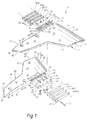
- Figure 1 is an exploded perspective view of one embodiment of the adjustable boat stabilizer of the present invention.
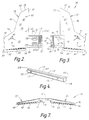
- Figures 2 and 3 are bottom views of the right side and left side lifting members of the stabilizer of Figure 1, respectively.
- Figure 4 is a perspective view of a spacer bar of the stabilizer of Figure 1.
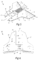
- Figures 5, 6 and 7 are a perspective view, a bottom view and a rear view of the stabilizer of Figure 1.
- Figure 8 illustrates how the stabiliser may be adjustable in width.
- Figure 9 illustrates a conventional boat motor and corresponding lower drive unit without a stabilizer attached.
- Figure 10 shows the boat motor of Figure 9 with the stabiliser attached.
- Figure 11 illustrates use of a torque equalizer in connection with the stabilizer of Figure 1.
- the stabilizer 20 is designed for attachment to the lower drive unit of an outboard or inboard/outboard (stern drive) boat motor.
- “lower drive unit” hereinafter “drive unit” means the portion of the boat motor connecting the actual engine to the propeller (sometimes called the motor post or propeller post).
- the drive unit In outboard motors, the drive unit extends directly from the engine into the water.
- inboard/outboard motors the drive unit extends from the engine through the stern of the boat and into the water.
- the stabilizer 20 comprises first and second lifting members 22 and 28, having first and second interior walls 23 and 30 for positioning adjacent to the sides of the drive unit and integral first and second arm portions 26 and 32 for extension around the drive unit.
- the first and second interior side walls 23 and 30 are mirror images of one another and define : slot 34 therebetween.
- the first lifting member 22 and second lifting member 28 also each include an upper surface 35 and a lower surface 37.
- the first and second arm portions 26 and 32 are removably attached together and can be selectively movable toward or away from each other for decreasing or increasing the distance between the side walls 23 and 30. Attachment of the lifting members 22 and 28 together adds a great deal of strength thereto. Attaching the first and second arm portions 26 and 32 together greatly improves the structural integrity and strength of the stabilizer 20 as a whole.
- the lifting members 22 and 28 each include a nose portion 36, having a leading edge 42, a sweeping body portion 38 and a flap portion 40.
- the sweeping body portions 38 each include a first wing section 44 having a leading edge 46 and a second wing section 48 having a leading edge 50 and side edge 52.
- the flap portions 40 each have an exterior side edge 54, an interior side edge 56 and a trailing edge 58.
- the first and second lifting members 22 and 28 each taper downwardly (first negative dihedral) and outwardly (second negative dihedral) from their nose portion 36 toward their trailing edge 58 and side edges 52 and 54.
- the negative dihedral angles are formed with respect to the surface to which the members 22 and 28 are attached.
- the lifting members 22 and 28 To allow the lifting members 22 and 28 to be bolted to the anti-cavitation plate or other portion of the drive unit, they include openings 60, each counter-sunk at 62 to receive the head of the bolt, to improve the hydrodynamic performance and aesthetic appeal of the stabilizer.
- the lower surfaces 37 of the lifting members 22 and 28 each include an opening 64 and a plurality of openings 66 for receiving an adjustable torque equalizer (not shown by Figures 1-8). The nature and function of such a torque equalizer are discussed in connection with reference to Figure 11 below.
- a textured surface 68 is provided on the upper surfaces 35 of the lifting members 22 and 28, preferably on the flap portion 40 and may also be provided on the lower surface. Due to the excellent structural relationship between the members 22 and 28, the stabilizer 20 can be used as a step by swimmers and skiers to get in and out of the boat.
- the textured surfaces 68 prevent the bare feet of the swimmers and skiers from slipping.
- the textured surfaces 68 may also function to reduce the boundary layer effect and improve the hydrodynamic performance thereof.
- the arm portions 26 and 32 include upper surfaces 70, 80, lower surfaces 72, 82, front walls 74, 84, rear walls 76, 86 and interior walls 78, 88.
- the front wall 84 of the second arm portion 32 can be tapered downwardly from top to bottom toward the rear wall 86 thereof.
- first and second arm portions 26 and 32 are selectively slidably positioned to overlap one another.
- the lower surface 37 of the first lifting member 22 has a first recess 90 formed therein forming a first shoulder 92 facing the second lifting member 28.
- the upper surface 80 of the second arm portion 32 provides a second recess 94 forming a second shoulder 96 facing the first lifting member 22.
- the first and second recesses 90 and 94 have approximately the same shape and depth as the shape and width of the second and first arm portions 32 and 26 respectively.
- a plurality of first and second spacer bars 98(a)-98(d) and 100(a)-100(d) are removably attached to the interior walls 78 and 88 of the first and second arm portions 26 and 32 respectively, being removably attached together side by side between the interior walls 78, 88 and the shoulder 96 and 92.
- the spacer bars 98 and 100 each include upper and lower surfaces 102, 104, end surfaces 106, 108, and exterior and interior side surfaces 110, 112.
- the exterior side surfaces 110 have upper and lower recesses 114, 116 which form a plurality of longitudinal grooves 118 when the spacers are attached together.
- Each spacer bar 98 and 100 is substantially rectangular in shape, has a length and height approximately equal to the length and height of the interior walls 78 and 88 of the arm portions 26 and 32 and is approximately 6.3 mm wide.
- the exterior sides 110 of the first of the spacer bars 98(a), 100(a) directly abut the interior walls 78, 88 of the arm portions 26, 32, while the interior sides 112 of the spacer bars 98(d), 100(d) directly abut the shoulders 96, 92.
- the spacer bars 98 and 100 impart a great deal of structural integrity and strength to the stabilizer 20 by reinforcing the overlap connection between the arm portions 26 and 32.
- the spacer bars 98 and 100 are illustrated in Figure 1 as having openings 120 therethrough.
- Complementary bores 122 are formed through the interior walls 78 and 88 of the arm portions 26 and 32 and screw 123 can be inserted through the openings 120 into the bores 122.
- This means of attaching the spacer bars 98 and 100 to the interior walls 78 and 88 and to each other allows any number of the spacer bars to be removed and reattached at any time.
- the spacer bars 98 and 100 can be integrally molded or otherwise formed with the arm portions 26 and 32, and can be removed by cutting them off with a saw or other tool. This means of attachment is advantageous because it increases the structural integrity and strength of the connection.
- the grooves 118 formed by the recesses 114 and 116 in the exterior sides 110 of the spacer bars 98 and 100 facilitate the cutting or removing process by acting as saw guides.
- the grooves 118 also function to improve the hydrodynamic performance as well as the aesthetic appeal of the stabilizer 20.
- a pair of apertures 126 are disposed in the first arm portion 26 and a pair of elongated slots 128 are disposed in the second arm portion 132.
- the longitudinal axes 130 of the slots 128 extend from points 132 adjacent to the second shoulder 94 toward the first lifting member 22.
- Hexagonal recesses 134 open into the upper surface 70 of the first arm portion 26 over the apertures 126 and receive nuts 140.
- a pair of bolts 135 extend from the lower surface 82 of the second arm portion 32 and through the slots 128 and apertures 126.
- the head portions 136 of the bolts 135 abut the lower surface 82 of the second arm portion 32, and the threaded end portions 138 of the bolts 135 are threaded into the nuts 140 to attach the first and second arm portions together.
- the location of nuts 140 in recesses 135 improves both the hydrodynamic performance and the aesthetic appeal of the stabilizer 20.
- the longitudinal slots 128 allow the first arm portion 26 to slide toward and away from the second shoulder 96 while the arm portions are attached together, so that the distance between the first interior side wall 23 and second interior side wall 30 of lifting members 22 and 28 can be easily adjusted in fitting the stabilizer onto the drive unit.
- the upper surfaces 70, 80 of the arm portions 26, 32 include a plurality of grooves 142, 144 for improving the hydrodynamic performance of the stabilizer 20 and matching the grooves 118.
- the lifting members 22 and 26, including the arm portions 26 and 32 and the spacer bars 98 and 100, are formed of a material that is stable at both high and low temperature, strong and durable, preferably of high molecular weight plastics such as polypropylene and rubber copolymers. Such plastics have a very high strength-to-weight ratio.
- a conventional outboard boat motor 150 is illustrated in Figures 9 and 10, connected to a transom portion 152 of the boat hull and includes a propeller 154 which is driven by a propeller shaft (not shown), the shaft being enclosed within a housing 156.
- a conventional anti-cavitation plate 160 which is disposed in a substantially horizontal position above the propeller to eliminate and reduce certain cavitation effects that would otherwise be created by rotation of the propeller.
- the boat motor 150 further includes a motor housing 162 and engine (not shown).
- the propeller 154, shaft, shaft housing 156 and anti-cavitation plate 160 form the lower drive unit 164, having front and rear ends 166, 168 and first and second mirror image sides 170, 172.
- the position of the stabilizer 20 with respect to the lower unit 164 is critical.
- the stabilizer can be attached on the lower unit at a variety of points above the propeller 154 in adjacent spaced relation therefrom as long as it is sufficiently submerged beneath the water to provide the desired amount of lift, it is preferably attached directly above, over or directly below the anti-cavitation plate 160.
- the anti-cavitation plate 160 will be 12.7 to 25.4 mm below the lowest point on the boat's transom/keel.
- the first and second lifting members 22, 28 are bolted to the top of the anti-cavitation plate 160 on the first and second sides 170, 172 of the drive unit 164 respectively.
- the side edges 52 of the second wing sections 48 and the side edges 54 of the flap portions 40 of the lifting members 22 and 28 will submerge in the water during turns made by the boat and as it rocks back and forth at cruising speeds.
- the stabilizer 20 is placed around the rear end 168 of the drive unit 164 over the anti-cavitation plate 160 thereof.
- the lifting members can be connected together at the nose portions thereof and the slot for receiving the lower unit can be positioned at the opposite end allowing the stabilizer to slide on to the lower unit from the front side thereof.
- the stabilizer 20 can be installed in a very short time. First, the stabilizer 20 is adjusted to the proper width, so that the interior side walls 23, 30 should fit tightly against the first and second sides 170 of the drive unit 164 with the trailing edges 58 of the lifting members perpendicular to the drive unit. Although it is effective in all positions, the stabilizer is most effective (e.g. provides more lift) when it is positioned as far to the rear end 168 of the lower unit 164 as possible. The stabilizer was designed such that most drive unit housings will not entirely fill the center slot 34. This allows for adequate water flow into the cooling intakes.
- the width of the slot 34 can be decreased from approximately 70 mm to 44.5 mm. This decreases the wingspan of the stabilizer from 356 mm to 330.4 mm. This width range allows the stabilizer to properly fit virtually any conventional lower drive unit.
- the first lifting member 22 is first removed from the second lifting member 28 by removing the bolts 35 from the apertures 126 and slots 128 and separating the members. The appropriate number of spacer bars are then removed from each arm portion. For example, if the slot 34 is 12.7 mm too wide, two spacer bars are removed from each arm portion.
- spacer bars are fastened to the interior walls of the arm portion and to each other by screws, these are removed and the spacer bars are removed starting with the spacer bars closest to the interior walls 78 and 88 of the arm portions.
- the spacer bars 98(a), 98(b), 100(a) and 100(b) are removed.
- an equal number of spacer bars must always be removed from each arm portion.
- the spacer bars are integrally formed with the arm portions and each other, the spacer bars are removed starting with the spacer bars furthest away from the interior walls 78 and 88 of the arm portions. In order to decrease the width of the slot by 12.7 mm, the spacer bars 98(c), 98(d), 100(c) and 100(d) are removed. Once the proper width of the slot 34 is achieved, the members 22 and 28 are fastened back together and the stabilizer 20 is mounted to the anti-cavitation plate. Four holes are drilled through the cavitation plate using the openings 66 as guides and the stabilizer is bolted thereto.
- the stabilizer 20 forces the stern of the boat up and keeps the bow down. It gets the boat up on plane in less than half the normal time and eliminates the dangerous and burdensome cavitation and porpoising associated with many boats. Boats with the stabilizer of the invention can pull skiers up faster with less power and are more stable with improved control and ride. The stabilizer can result in a savings in fuel and an increae in top end speed.
- the stabilizer 20 functions by creating a higher water pressure on the lower surfaces of the lifting members which forces the stern of the boat up.
- the rear upward force even at low speeds, keeps the bow down and causes the boat to plane in less time with less power.
- the stabilizer has a very low drag coefficient which brings out the hidden peak performance of every boat. Boats having the stabilizer 20 attached thereto handle, ride and track (even in turns) better.
- the stabilizer is easy to install, virtually indestructible and does not require any maintenance.
- the fact that it is adjustable in width allows it to be used in connection with boat motors having anywhere from one or two horsepower to three hundred horsepower and up. It can be used in connection with big or small runabouts, ski boats, bass boats, pontoon boats, inflatable boats and cruisers.
- the stabilizer allows boats to turn without cavitating and it allows for better stability and manoeuvrability at high speeds and reduces the annoying back-and-forth wander at low speeds.
- a torque equalizer 174 can be attached to the lower surfaces 37 of both lifting members 22 and 28. Using the openings 64 as guides, holes are drilled through the lifting members and bolts are inserted from the upper surfaces 35 of the lifting members through the openings 64 into corresponding openings 178 in the upper surfaces 180 of the torque equalizers.
- the torque equalizers can be positioned at various 10° angle increments (up to 40° right or left) to provide for maximum latitude and adjustment. Pegs 182 on the upper surfaces 180 of the equalizers are positioned in the appropriate openings 66 in the lower surfaces 37 of the lifting members.
- the torque equalizers function to neutralize tiresome and dangerous steering/propeller torque experienced by all boats.
- Boats having the stabilizer 20 and corresponding torque equalizers 174 attached thereto track straighter and are easier to control. It is the positioning and shape of the stabilizer 20 that allows the torque equalizers 176 to function so well.
- the torque equalizers 174 can be made of the same material that forms the stabilizer 20.
Landscapes
- Chemical & Material Sciences (AREA)
- Engineering & Computer Science (AREA)
- Combustion & Propulsion (AREA)
- Mechanical Engineering (AREA)
- Ocean & Marine Engineering (AREA)
- Vehicle Body Suspensions (AREA)
- Gas Or Oil Filled Cable Accessories (AREA)
Claims (8)
- Bootsstabilisator (20) zur Anbringung an der unteren Antriebseinheit (164) eines Bootsmotors (150), mit einem ersten Auftriebsteil (22), das eine erste innere Seitenwand (23) zur Positionierung benachbart zu einer ersten Seite (170) der Antriebseinheit (164) und einen ersten Armabschnitt (26) zur Erstreckung um die Antriebseinheit herum aufweist, und einem zweiten Auftriebsteil (28), das eine zweite innere Seitenwand (30) zur Positionierung benachbart zu einer zweiten Seite (172) der Antriebseinheit (164) und einen zweiten Armabschnitt (32) zur Erstreckung um die Antriebseinheit herum zum ersten Armabschnitt (26) hin aufweist, wobei die zweite innere Seitenwand (30) von der ersten inneren Seitenwand (23) beabstandet ist und ihr gegenüberliegt und wobei die ersten und zweiten Armabschnitte (26,32) miteinander befestigt sind und selektiv aufeinanderzu bewegbar sind, um den Abstand zwischen der ersten inneren Seitenwand und der zweiten inneren Seitenwand zu verringern.
- Bootsstabilisator nach Anspruch 1,
dadurch gekennzeichnet,
daß die ersten und zweiten Armabschnitte (26,32) selektiv gleitbar übereinander überlappend positioniert sind. - Bootsstabilisator nach Anspruch 2,
dadurch gekennzeichnet,
daß das erste Auftriebsteil (22) eine erste Schulter (92) aufweist, die dem zweiten Auftriebsteil (28) zugewandt ist,
daß das zweite Auftriebsteil (28) eine zweite Schulter (96) aufweist, die dem ersten Auftriebsteil (22) zugewandt ist,
daß der erste Armabschnitt (26) eine obere Fläche (70), eine untere Fläche (72) und eine erste innere Wand (78) aufweist, wobei die erste innere Wand der zweiten Schulter zugewandt ist, und
daß der zweite Armabschnitt (32) eine obere Fläche (80), eine untere Fläche (82) und eine zweite innere Wand (88) aufweist, wobei die zweite innere Wand der ersten Schulter zugewandt ist. - Bootsstabilisator nach Anspruch 3,
dadurch gekennzeichnet,
daß die ersten und zweiten Armabschnitte (22,26) obere Flächen (70,80) und untere Flächen (72,82) aufweisen, wobei die untere Fläche (72) des ersten Armabschnittes eine erste Ausnehmung (90) aufweist, die die erste Schulter (92) bildet, wobei die obere Fläche (80) des zweiten Armabschnittes eine zweite Ausnehmung (94) aufweist, die die zweite Schulter (96) bildet. - Bootsstabilisator nach Anspruch 3 oder 4,
dadurch gekennzeichnet,
daß zumindest ein erster Abstandsbalken (98) am ersten Armabschnitt abnehmbar angebracht und zwischen der ersten inneren Wand (78) und der zweiten Schulter (96) angeordnet ist, wobei der zumindest eine Abstandsbalken eine äußere Seite (110) aufweist, die an der ersten inneren Wand (78) anliegt, und eine innere Seite (112) aufweist, die an der zweiten Schulter (96) anliegt, und
daß zumindest ein zweiter Abstandsbalken (100) am zweiten Armabschnitt abnehmbar befestigt ist und zwischen der zweiten inneren Wand (88) und der ersten Schulter (92) angeordnet ist, wobei der zumindest eine zweite Abstandsbalken eine äußere Seite (110) aufweist, die an der inneren Wand (88) anliegt und eine innere Seite (112) aufweist, die an der ersten Schulter (92) anliegt. - Bootsstabilisator nach Anspruch 5,
dadurch gekennzeichnet,
daß eine Mehrzahl von ersten Abstandsbalken (98) am ersten Armabschnitt abnehmbar befestigt ist, und daß die Abstandsbalken zwischen der ersten inneren Wand und der zweiten Schulter nebeneinander abnehmbar miteinander befestigt sind, wobei der erste, der ersten inneren Wand nächstgelegene Abstandsbalken eine äußere Seite aufweist, die an der ersten inneren Wand anliegt, und wobei der erste, der zweiten Schulter nächstgelegene Abstandsbalken eine innere Seite aufweist, die an der zweiten Schulter anliegt, und daß eine Mehrzahl von zweiten Abstandsbalken (100) am zweiten Armabschnitt abnehmbar befestigt ist, und daß die zweiten Abstandsbalken zwischen der zweiten inneren Wand und der ersten Schulter nebeneinander abnehmbar miteinander befestigt sind, wobei der zweite, der zweiten inneren Wand nächstgelegene Abstandsbalken eine äußere Seite besitzt, die an der zweiten inneren Wand anliegt, und wobei der zweite, der ersten Schulter nächstgelegene Abstandsbalken eine innere Seite aufweist, die an der ersten Schulter anliegt. - Bootsstabilisator nach einem der Ansprüche 1 bis 4,
dadurch gekennzeichnet,
daß eine Mehrzahl von ersten Abstandsbalken (98) mit dem ersten Armabschnitt (26) integral ausgebildet ist, daß eine Mehrzahl von zweiten Abstandsbalken (100) mit dem zweiten Armabschnitt (32) integral ausgebildet ist, und
daß eine ausgewählte Anzahl der ersten und zweiten Abstandsbalken vom ersten und zweiten Armabschnitt entfernt werden kann. - Bootsstabilisator nach einem der vorhergehenden Ansprüche,
dadurch gekennzeichnet,
daß der erste Armabschnitt (26) zumindest eine Öffnung (126) aufweist, die sich zwischen dessen oberer und unterer Fläche erstreckt,
daß der zweite Armabschnitt (32) zumindest einen Längsschlitz (128) aufweist, der sich zwischen dessen oberer und unterer Fläche erstreckt, wobei sich die Längsachse des Schlitzes zum ersten Auftriebsteil erstreckt, und daß sich ein Bolzen (135) durch jede Öffnung (126) und den Längsschlitz (128) hindurcherstreckt, und daß eine Mutter (140) auf jeden Bolzen aufgeschraubt ist, um die ersten und zweiten Armabschnitte miteinander zu befestigen.
Applications Claiming Priority (2)
| Application Number | Priority Date | Filing Date | Title |
|---|---|---|---|
| US07/478,589 US5048449A (en) | 1988-06-23 | 1990-02-09 | Adjustable boat stabilizer |
| US478589 | 2000-01-06 |
Publications (2)
| Publication Number | Publication Date |
|---|---|
| EP0445922A1 EP0445922A1 (de) | 1991-09-11 |
| EP0445922B1 true EP0445922B1 (de) | 1994-01-26 |
Family
ID=23900535
Family Applications (1)
| Application Number | Title | Priority Date | Filing Date |
|---|---|---|---|
| EP91300993A Expired - Lifetime EP0445922B1 (de) | 1990-02-09 | 1991-02-06 | Bootstabilisierungsflächen |
Country Status (8)
| Country | Link |
|---|---|
| US (1) | US5048449A (de) |
| EP (1) | EP0445922B1 (de) |
| JP (1) | JPH04212697A (de) |
| AU (1) | AU643745B2 (de) |
| CA (1) | CA2022893C (de) |
| DE (1) | DE69101068T2 (de) |
| DK (1) | DK0445922T3 (de) |
| ES (1) | ES2051080T3 (de) |
Families Citing this family (26)
| Publication number | Priority date | Publication date | Assignee | Title |
|---|---|---|---|---|
| FR2655988B1 (fr) * | 1989-12-20 | 1994-05-20 | Adir Cie | Nouveaux derives de la napht-1-yl piperazine, leur procede de preparation et les compositions pharmaceutiques qui les contiennent. |
| USD331738S (en) | 1991-03-22 | 1992-12-15 | Action Products Co., Inc. | Boat stabilizer |
| US5178089A (en) * | 1991-09-09 | 1993-01-12 | Arnold Hodel | Motor boat hydrofoil |
| US5231950A (en) * | 1991-10-07 | 1993-08-03 | Poulos John G | Hydrofoil for watercraft |
| US5638765A (en) * | 1991-10-07 | 1997-06-17 | Poulos; John George | Hydrofoil assembly for marine use, and method for mounting the same |
| US5215029A (en) * | 1992-05-22 | 1993-06-01 | Davis Mckay H | Hydroplaning boat accessory |
| USD363914S (en) | 1994-10-31 | 1995-11-07 | Corn James F | Boat stabilizer |
| US6588360B1 (en) | 2002-04-17 | 2003-07-08 | Helmuth G. Bachmann | Detachable planing enhancement system for inflatable sportboats |
| USD533497S1 (en) | 2003-11-07 | 2006-12-12 | Marine Dynamics, Inc. | Boat stabilizer |
| AU2006304066B2 (en) * | 2005-10-19 | 2010-09-23 | Marine Dynamics, Inc. | Boat stabilizer, boat motor and related method |
| US7520238B2 (en) * | 2006-09-25 | 2009-04-21 | Robert Michael Patterson | Boat stabilizer |
| USD590760S1 (en) * | 2006-10-06 | 2009-04-21 | Marine Dynamics, Inc. | Boat stabilizer |
| USD589866S1 (en) * | 2006-10-06 | 2009-04-07 | Marine Dynamics, Inc. | Boat stabilizer |
| US8145369B1 (en) | 2007-11-01 | 2012-03-27 | Vehicle Control Technologles, Inc. | Docking apparatuses and methods |
| USD580341S1 (en) * | 2007-11-01 | 2008-11-11 | Vehicle Control Technologies, Inc. | Docking slot portion of an object |
| US8636553B1 (en) | 2008-04-29 | 2014-01-28 | Sport Marine Technologies, Inc. | Assembly and method to attach a device such as a hydrofoil to an anti-ventilation plate |
| US9120534B1 (en) | 2008-04-29 | 2015-09-01 | Sport Marine Technologies, Inc. | Assembly and method to attach a device such as a hydrofoil to an antiventilation plate |
| USD591664S1 (en) | 2008-04-29 | 2009-05-05 | Sport Marine Technologies, Inc. | Boating accessory |
| US8043135B1 (en) | 2008-04-29 | 2011-10-25 | Sport Marine Technologies, Inc. | Assembly and method to attach a device such as a hydrofoil to an anti-ventilation plate |
| USD630994S1 (en) | 2009-07-13 | 2011-01-18 | Vehicle Control Technologies, Inc. | Apparatus for mechanically guiding a water vehicle that is being released or retrieved |
| US8430049B1 (en) | 2009-07-13 | 2013-04-30 | Vehicle Control Technologies, Inc. | Launch and recovery systems and methods |
| US8312831B2 (en) | 2010-06-29 | 2012-11-20 | Marine Dynamics, Inc. | Hydrofoil boat stabilizer |
| USD728444S1 (en) | 2013-05-17 | 2015-05-05 | Sport Marine Technologies, Inc. | Boating accessory |
| USD909948S1 (en) * | 2019-01-17 | 2021-02-09 | Dale MacDonald | Hydrofoil shield |
| US11312459B2 (en) | 2019-02-20 | 2022-04-26 | Brian Jordan | Outboard motor support |
| USD913192S1 (en) * | 2019-02-28 | 2021-03-16 | I-Sin Peng | Hydrofoil |
Family Cites Families (6)
| Publication number | Priority date | Publication date | Assignee | Title |
|---|---|---|---|---|
| US2021309A (en) * | 1933-02-10 | 1935-11-19 | Outboard Motors Corp | Lower unit for outboard motors |
| SE7700478L (sv) * | 1977-01-18 | 1978-07-19 | Olsson Gerhard Gunnar Rinaldo | Som stabilisator for en med motor driven bat avsedd anordning |
| JPS55119594A (en) * | 1979-03-06 | 1980-09-13 | Yamaha Motor Co Ltd | Splash plate of marine propulsion machinery |
| US4756265A (en) * | 1986-08-12 | 1988-07-12 | Lane H T | High speed boat lifting structures |
| US4738644A (en) * | 1987-02-27 | 1988-04-19 | Thomas Happel | Outboard motor attachment and method |
| US4977847A (en) * | 1989-07-20 | 1990-12-18 | Bartlett Dana W | Lift and rudder fin attachment |
-
1990
- 1990-02-09 US US07/478,589 patent/US5048449A/en not_active Expired - Lifetime
- 1990-08-08 CA CA002022893A patent/CA2022893C/en not_active Expired - Lifetime
-
1991
- 1991-02-06 DK DK91300993.2T patent/DK0445922T3/da active
- 1991-02-06 EP EP91300993A patent/EP0445922B1/de not_active Expired - Lifetime
- 1991-02-06 DE DE91300993T patent/DE69101068T2/de not_active Expired - Fee Related
- 1991-02-06 ES ES91300993T patent/ES2051080T3/es not_active Expired - Lifetime
- 1991-02-08 AU AU70893/91A patent/AU643745B2/en not_active Ceased
- 1991-02-08 JP JP3037723A patent/JPH04212697A/ja active Pending
Also Published As
| Publication number | Publication date |
|---|---|
| DK0445922T3 (da) | 1994-05-02 |
| ES2051080T3 (es) | 1994-06-01 |
| JPH04212697A (ja) | 1992-08-04 |
| CA2022893C (en) | 1995-04-25 |
| AU7089391A (en) | 1991-08-15 |
| DE69101068T2 (de) | 1994-05-05 |
| DE69101068D1 (de) | 1994-03-10 |
| EP0445922A1 (de) | 1991-09-11 |
| US5048449A (en) | 1991-09-17 |
| AU643745B2 (en) | 1993-11-25 |
Similar Documents
| Publication | Publication Date | Title |
|---|---|---|
| EP0445922B1 (de) | Bootstabilisierungsflächen | |
| US5107786A (en) | Adjustable boat stabilizer | |
| US4492176A (en) | Boat hull | |
| KR100293301B1 (ko) | 고성능동력수상스키 | |
| US5878686A (en) | Pivotal afterplane having a motor positioned thereon | |
| CA1335059C (en) | Stabilizing fin for a motor boat | |
| US5063868A (en) | Boat hull for V-bottom powerboats | |
| CA2651339C (en) | Foam stabilized watercraft with finned collar | |
| US5638765A (en) | Hydrofoil assembly for marine use, and method for mounting the same | |
| US4361102A (en) | Vee type planing hull for power boats | |
| US4027613A (en) | Planing boat hull | |
| US6053789A (en) | Surfboard fin pivotal mechanism | |
| US5307754A (en) | Hydrofoil stabilizer | |
| WO1990006883A1 (en) | Apparatus for automatically raising and lowering boat motors | |
| US4398483A (en) | Vee type planing hull with AFT tapered wedges | |
| US4958585A (en) | Boat hull | |
| US6546888B2 (en) | Removable stabilizing fin for a watercraft | |
| US4875426A (en) | Float attachment for watercrafts | |
| CA1258005A (en) | Transom bracket water deflector for improved boat performance | |
| US20120240839A1 (en) | Swimming Platform for a Boat | |
| US4652245A (en) | Shallow draft boat | |
| US7192323B2 (en) | Stabilizer device | |
| GB2213788A (en) | Propellor guard | |
| US4592299A (en) | Ship's-vessel's rudder with reduced drag effected factors | |
| US20010023658A1 (en) | Motor powered catamaran |
Legal Events
| Date | Code | Title | Description |
|---|---|---|---|
| PUAI | Public reference made under article 153(3) epc to a published international application that has entered the european phase |
Free format text: ORIGINAL CODE: 0009012 |
|
| AK | Designated contracting states |
Kind code of ref document: A1 Designated state(s): BE DE DK ES FR GB GR IT NL SE |
|
| 17P | Request for examination filed |
Effective date: 19920224 |
|
| 17Q | First examination report despatched |
Effective date: 19930414 |
|
| GRAA | (expected) grant |
Free format text: ORIGINAL CODE: 0009210 |
|
| AK | Designated contracting states |
Kind code of ref document: B1 Designated state(s): BE DE DK ES FR GB GR IT NL SE |
|
| PG25 | Lapsed in a contracting state [announced via postgrant information from national office to epo] |
Ref country code: SE Effective date: 19940126 |
|
| PGFP | Annual fee paid to national office [announced via postgrant information from national office to epo] |
Ref country code: SE Payment date: 19940225 Year of fee payment: 4 |
|
| REF | Corresponds to: |
Ref document number: 69101068 Country of ref document: DE Date of ref document: 19940310 |
|
| ET | Fr: translation filed | ||
| ITF | It: translation for a ep patent filed | ||
| REG | Reference to a national code |
Ref country code: DK Ref legal event code: T3 |
|
| REG | Reference to a national code |
Ref country code: ES Ref legal event code: FG2A Ref document number: 2051080 Country of ref document: ES Kind code of ref document: T3 |
|
| REG | Reference to a national code |
Ref country code: GR Ref legal event code: FG4A Free format text: 3011573 |
|
| PLBE | No opposition filed within time limit |
Free format text: ORIGINAL CODE: 0009261 |
|
| STAA | Information on the status of an ep patent application or granted ep patent |
Free format text: STATUS: NO OPPOSITION FILED WITHIN TIME LIMIT |
|
| 26N | No opposition filed | ||
| PGFP | Annual fee paid to national office [announced via postgrant information from national office to epo] |
Ref country code: DK Payment date: 19960207 Year of fee payment: 6 |
|
| PGFP | Annual fee paid to national office [announced via postgrant information from national office to epo] |
Ref country code: DE Payment date: 19960215 Year of fee payment: 6 |
|
| PGFP | Annual fee paid to national office [announced via postgrant information from national office to epo] |
Ref country code: FR Payment date: 19960216 Year of fee payment: 6 |
|
| PGFP | Annual fee paid to national office [announced via postgrant information from national office to epo] |
Ref country code: NL Payment date: 19960229 Year of fee payment: 6 |
|
| PG25 | Lapsed in a contracting state [announced via postgrant information from national office to epo] |
Ref country code: DK Effective date: 19970206 |
|
| REG | Reference to a national code |
Ref country code: DK Ref legal event code: EBP |
|
| PGFP | Annual fee paid to national office [announced via postgrant information from national office to epo] |
Ref country code: GR Payment date: 19970219 Year of fee payment: 7 |
|
| PGFP | Annual fee paid to national office [announced via postgrant information from national office to epo] |
Ref country code: BE Payment date: 19970410 Year of fee payment: 7 |
|
| PG25 | Lapsed in a contracting state [announced via postgrant information from national office to epo] |
Ref country code: NL Effective date: 19970901 |
|
| PG25 | Lapsed in a contracting state [announced via postgrant information from national office to epo] |
Ref country code: FR Effective date: 19971030 |
|
| PG25 | Lapsed in a contracting state [announced via postgrant information from national office to epo] |
Ref country code: DE Effective date: 19971101 |
|
| NLV4 | Nl: lapsed or anulled due to non-payment of the annual fee |
Effective date: 19970901 |
|
| REG | Reference to a national code |
Ref country code: FR Ref legal event code: ST |
|
| PG25 | Lapsed in a contracting state [announced via postgrant information from national office to epo] |
Ref country code: GR Free format text: LAPSE BECAUSE OF NON-PAYMENT OF DUE FEES Effective date: 19980228 Ref country code: BE Free format text: LAPSE BECAUSE OF NON-PAYMENT OF DUE FEES Effective date: 19980228 |
|
| BERE | Be: lapsed |
Owner name: MARINE DYNAMICS INC. Effective date: 19980228 |
|
| REG | Reference to a national code |
Ref country code: GB Ref legal event code: IF02 |
|
| PGFP | Annual fee paid to national office [announced via postgrant information from national office to epo] |
Ref country code: ES Payment date: 20030221 Year of fee payment: 13 |
|
| PG25 | Lapsed in a contracting state [announced via postgrant information from national office to epo] |
Ref country code: ES Free format text: LAPSE BECAUSE OF NON-PAYMENT OF DUE FEES Effective date: 20040207 |
|
| PGFP | Annual fee paid to national office [announced via postgrant information from national office to epo] |
Ref country code: GB Payment date: 20040211 Year of fee payment: 14 |
|
| PG25 | Lapsed in a contracting state [announced via postgrant information from national office to epo] |
Ref country code: IT Free format text: LAPSE BECAUSE OF NON-PAYMENT OF DUE FEES Effective date: 20050206 Ref country code: GB Free format text: LAPSE BECAUSE OF NON-PAYMENT OF DUE FEES Effective date: 20050206 |
|
| REG | Reference to a national code |
Ref country code: ES Ref legal event code: FD2A Effective date: 20040207 |
|
| GBPC | Gb: european patent ceased through non-payment of renewal fee |
Effective date: 20050205 |