EP0445597B1 - Method and device for gaseous fuel cell operation - Google Patents
Method and device for gaseous fuel cell operation Download PDFInfo
- Publication number
- EP0445597B1 EP0445597B1 EP91102546A EP91102546A EP0445597B1 EP 0445597 B1 EP0445597 B1 EP 0445597B1 EP 91102546 A EP91102546 A EP 91102546A EP 91102546 A EP91102546 A EP 91102546A EP 0445597 B1 EP0445597 B1 EP 0445597B1
- Authority
- EP
- European Patent Office
- Prior art keywords
- fuel
- fuel cell
- chamber
- electrodes
- wall
- Prior art date
- Legal status (The legal status is an assumption and is not a legal conclusion. Google has not performed a legal analysis and makes no representation as to the accuracy of the status listed.)
- Expired - Lifetime
Links
- 239000000446 fuel Substances 0.000 title claims description 96
- 238000000034 method Methods 0.000 title claims description 10
- 239000000203 mixture Substances 0.000 claims description 43
- VNWKTOKETHGBQD-UHFFFAOYSA-N methane Chemical compound C VNWKTOKETHGBQD-UHFFFAOYSA-N 0.000 claims description 38
- 239000007789 gas Substances 0.000 claims description 37
- 239000003792 electrolyte Substances 0.000 claims description 24
- 239000007800 oxidant agent Substances 0.000 claims description 24
- 239000007784 solid electrolyte Substances 0.000 claims description 24
- 230000001590 oxidative effect Effects 0.000 claims description 22
- 238000005192 partition Methods 0.000 claims description 21
- BASFCYQUMIYNBI-UHFFFAOYSA-N platinum Chemical compound [Pt] BASFCYQUMIYNBI-UHFFFAOYSA-N 0.000 claims description 13
- 230000005611 electricity Effects 0.000 claims description 11
- MCMNRKCIXSYSNV-UHFFFAOYSA-N Zirconium dioxide Chemical compound O=[Zr]=O MCMNRKCIXSYSNV-UHFFFAOYSA-N 0.000 claims description 9
- 239000000463 material Substances 0.000 claims description 9
- VYPSYNLAJGMNEJ-UHFFFAOYSA-N Silicium dioxide Chemical compound O=[Si]=O VYPSYNLAJGMNEJ-UHFFFAOYSA-N 0.000 claims description 8
- PXHVJJICTQNCMI-UHFFFAOYSA-N Nickel Chemical compound [Ni] PXHVJJICTQNCMI-UHFFFAOYSA-N 0.000 claims description 6
- KDLHZDBZIXYQEI-UHFFFAOYSA-N Palladium Chemical compound [Pd] KDLHZDBZIXYQEI-UHFFFAOYSA-N 0.000 claims description 6
- 239000002001 electrolyte material Substances 0.000 claims description 6
- 229910052697 platinum Inorganic materials 0.000 claims description 6
- 239000011343 solid material Substances 0.000 claims description 6
- 229910001233 yttria-stabilized zirconia Inorganic materials 0.000 claims description 5
- 238000003487 electrochemical reaction Methods 0.000 claims description 4
- 239000000377 silicon dioxide Substances 0.000 claims description 4
- BQCADISMDOOEFD-UHFFFAOYSA-N Silver Chemical compound [Ag] BQCADISMDOOEFD-UHFFFAOYSA-N 0.000 claims description 3
- RTAQQCXQSZGOHL-UHFFFAOYSA-N Titanium Chemical compound [Ti] RTAQQCXQSZGOHL-UHFFFAOYSA-N 0.000 claims description 3
- PNEYBMLMFCGWSK-UHFFFAOYSA-N aluminium oxide Inorganic materials [O-2].[O-2].[O-2].[Al+3].[Al+3] PNEYBMLMFCGWSK-UHFFFAOYSA-N 0.000 claims description 3
- 239000002737 fuel gas Substances 0.000 claims description 3
- 239000010931 gold Substances 0.000 claims description 3
- 229910052759 nickel Inorganic materials 0.000 claims description 3
- 229910052763 palladium Inorganic materials 0.000 claims description 3
- 229910052709 silver Inorganic materials 0.000 claims description 3
- 239000004332 silver Substances 0.000 claims description 3
- 229910052719 titanium Inorganic materials 0.000 claims description 3
- 239000010936 titanium Substances 0.000 claims description 3
- PCHJSUWPFVWCPO-UHFFFAOYSA-N gold Chemical compound [Au] PCHJSUWPFVWCPO-UHFFFAOYSA-N 0.000 claims description 2
- 229910052737 gold Inorganic materials 0.000 claims description 2
- RUDFQVOCFDJEEF-UHFFFAOYSA-N yttrium(III) oxide Inorganic materials [O-2].[O-2].[O-2].[Y+3].[Y+3] RUDFQVOCFDJEEF-UHFFFAOYSA-N 0.000 claims description 2
- 229910002084 calcia-stabilized zirconia Inorganic materials 0.000 claims 2
- ODINCKMPIJJUCX-UHFFFAOYSA-N Calcium oxide Chemical compound [Ca]=O ODINCKMPIJJUCX-UHFFFAOYSA-N 0.000 claims 1
- 239000000292 calcium oxide Substances 0.000 claims 1
- 235000012255 calcium oxide Nutrition 0.000 claims 1
- 229910002077 partially stabilized zirconia Inorganic materials 0.000 claims 1
- 239000000126 substance Substances 0.000 description 6
- OTMSDBZUPAUEDD-UHFFFAOYSA-N Ethane Chemical compound CC OTMSDBZUPAUEDD-UHFFFAOYSA-N 0.000 description 5
- 238000006243 chemical reaction Methods 0.000 description 4
- 238000007254 oxidation reaction Methods 0.000 description 3
- CURLTUGMZLYLDI-UHFFFAOYSA-N Carbon dioxide Chemical compound O=C=O CURLTUGMZLYLDI-UHFFFAOYSA-N 0.000 description 2
- 230000004888 barrier function Effects 0.000 description 2
- CETPSERCERDGAM-UHFFFAOYSA-N ceric oxide Chemical compound O=[Ce]=O CETPSERCERDGAM-UHFFFAOYSA-N 0.000 description 2
- 229910000422 cerium(IV) oxide Inorganic materials 0.000 description 2
- 229910052681 coesite Inorganic materials 0.000 description 2
- 229910052906 cristobalite Inorganic materials 0.000 description 2
- 238000010586 diagram Methods 0.000 description 2
- 239000007772 electrode material Substances 0.000 description 2
- 230000006872 improvement Effects 0.000 description 2
- -1 molecular oxygen Chemical compound 0.000 description 2
- 229910052760 oxygen Inorganic materials 0.000 description 2
- 239000001301 oxygen Substances 0.000 description 2
- 235000012239 silicon dioxide Nutrition 0.000 description 2
- 239000007787 solid Substances 0.000 description 2
- 230000000638 stimulation Effects 0.000 description 2
- 229910052682 stishovite Inorganic materials 0.000 description 2
- 229910052905 tridymite Inorganic materials 0.000 description 2
- MYMOFIZGZYHOMD-UHFFFAOYSA-N Dioxygen Chemical compound O=O MYMOFIZGZYHOMD-UHFFFAOYSA-N 0.000 description 1
- 150000001335 aliphatic alkanes Chemical class 0.000 description 1
- 150000001336 alkenes Chemical class 0.000 description 1
- QVGXLLKOCUKJST-UHFFFAOYSA-N atomic oxygen Chemical compound [O] QVGXLLKOCUKJST-UHFFFAOYSA-N 0.000 description 1
- 229910000416 bismuth oxide Inorganic materials 0.000 description 1
- 239000006227 byproduct Substances 0.000 description 1
- 229910002092 carbon dioxide Inorganic materials 0.000 description 1
- 239000001569 carbon dioxide Substances 0.000 description 1
- 238000002485 combustion reaction Methods 0.000 description 1
- 239000004020 conductor Substances 0.000 description 1
- 229910052593 corundum Inorganic materials 0.000 description 1
- 239000013078 crystal Substances 0.000 description 1
- 230000007423 decrease Effects 0.000 description 1
- 238000001514 detection method Methods 0.000 description 1
- TYIXMATWDRGMPF-UHFFFAOYSA-N dibismuth;oxygen(2-) Chemical compound [O-2].[O-2].[O-2].[Bi+3].[Bi+3] TYIXMATWDRGMPF-UHFFFAOYSA-N 0.000 description 1
- 238000009792 diffusion process Methods 0.000 description 1
- 229910001882 dioxygen Inorganic materials 0.000 description 1
- 230000000977 initiatory effect Effects 0.000 description 1
- 150000002500 ions Chemical class 0.000 description 1
- 239000007788 liquid Substances 0.000 description 1
- 229910052751 metal Inorganic materials 0.000 description 1
- 239000002184 metal Substances 0.000 description 1
- 229910044991 metal oxide Inorganic materials 0.000 description 1
- 150000004706 metal oxides Chemical class 0.000 description 1
- 150000002739 metals Chemical class 0.000 description 1
- VUZPPFZMUPKLLV-UHFFFAOYSA-N methane;hydrate Chemical compound C.O VUZPPFZMUPKLLV-UHFFFAOYSA-N 0.000 description 1
- 230000005012 migration Effects 0.000 description 1
- 238000013508 migration Methods 0.000 description 1
- 230000003647 oxidation Effects 0.000 description 1
- AHKZTVQIVOEVFO-UHFFFAOYSA-N oxide(2-) Chemical compound [O-2] AHKZTVQIVOEVFO-UHFFFAOYSA-N 0.000 description 1
- RVTZCBVAJQQJTK-UHFFFAOYSA-N oxygen(2-);zirconium(4+) Chemical compound [O-2].[O-2].[Zr+4] RVTZCBVAJQQJTK-UHFFFAOYSA-N 0.000 description 1
- 230000008569 process Effects 0.000 description 1
- 230000002269 spontaneous effect Effects 0.000 description 1
- 239000002918 waste heat Substances 0.000 description 1
- XLYOFNOQVPJJNP-UHFFFAOYSA-N water Substances O XLYOFNOQVPJJNP-UHFFFAOYSA-N 0.000 description 1
- 229910001845 yogo sapphire Inorganic materials 0.000 description 1
- 229910052845 zircon Inorganic materials 0.000 description 1
- 229910001928 zirconium oxide Inorganic materials 0.000 description 1
- GFQYVLUOOAAOGM-UHFFFAOYSA-N zirconium(iv) silicate Chemical compound [Zr+4].[O-][Si]([O-])([O-])[O-] GFQYVLUOOAAOGM-UHFFFAOYSA-N 0.000 description 1
Images



Classifications
-
- G—PHYSICS
- G01—MEASURING; TESTING
- G01N—INVESTIGATING OR ANALYSING MATERIALS BY DETERMINING THEIR CHEMICAL OR PHYSICAL PROPERTIES
- G01N27/00—Investigating or analysing materials by the use of electric, electrochemical, or magnetic means
- G01N27/26—Investigating or analysing materials by the use of electric, electrochemical, or magnetic means by investigating electrochemical variables; by using electrolysis or electrophoresis
- G01N27/416—Systems
- G01N27/417—Systems using cells, i.e. more than one cell and probes with solid electrolytes
-
- H—ELECTRICITY
- H01—ELECTRIC ELEMENTS
- H01M—PROCESSES OR MEANS, e.g. BATTERIES, FOR THE DIRECT CONVERSION OF CHEMICAL ENERGY INTO ELECTRICAL ENERGY
- H01M8/00—Fuel cells; Manufacture thereof
- H01M8/04—Auxiliary arrangements, e.g. for control of pressure or for circulation of fluids
- H01M8/04082—Arrangements for control of reactant parameters, e.g. pressure or concentration
- H01M8/04089—Arrangements for control of reactant parameters, e.g. pressure or concentration of gaseous reactants
-
- H—ELECTRICITY
- H01—ELECTRIC ELEMENTS
- H01M—PROCESSES OR MEANS, e.g. BATTERIES, FOR THE DIRECT CONVERSION OF CHEMICAL ENERGY INTO ELECTRICAL ENERGY
- H01M8/00—Fuel cells; Manufacture thereof
- H01M8/10—Fuel cells with solid electrolytes
- H01M8/12—Fuel cells with solid electrolytes operating at high temperature, e.g. with stabilised ZrO2 electrolyte
- H01M8/1231—Fuel cells with solid electrolytes operating at high temperature, e.g. with stabilised ZrO2 electrolyte with both reactants being gaseous or vaporised
-
- Y—GENERAL TAGGING OF NEW TECHNOLOGICAL DEVELOPMENTS; GENERAL TAGGING OF CROSS-SECTIONAL TECHNOLOGIES SPANNING OVER SEVERAL SECTIONS OF THE IPC; TECHNICAL SUBJECTS COVERED BY FORMER USPC CROSS-REFERENCE ART COLLECTIONS [XRACs] AND DIGESTS
- Y02—TECHNOLOGIES OR APPLICATIONS FOR MITIGATION OR ADAPTATION AGAINST CLIMATE CHANGE
- Y02E—REDUCTION OF GREENHOUSE GAS [GHG] EMISSIONS, RELATED TO ENERGY GENERATION, TRANSMISSION OR DISTRIBUTION
- Y02E60/00—Enabling technologies; Technologies with a potential or indirect contribution to GHG emissions mitigation
- Y02E60/30—Hydrogen technology
- Y02E60/50—Fuel cells
Definitions
- the present invention relates to a method and apparatus for converting chemical energy to electrical energy for power usage or gas-sensing applications. More specifically, the present invention describes a fuel cell that uses a single gas mixture, such as methane and air, to achieve the spontaneous conversion of chemical energy into electrical energy.
- a single gas mixture such as methane and air
- a fuel cell is an electrochemical device that continuously converts the chemical energy of a fuel, such as methane, and an oxidant, such as molecular oxygen, to electrical energy.
- the fuel and oxidant are continuously supplied to the fuel cell from an external source.
- the fuel and oxidant are supplied to chambers of the fuel cell which are separated by an electrolyte barrier.
- This electrolyte barrier can be liquid or molten electrolyte, however, the present invention is concerned with solid electrolytes.
- fuel cells produce power by an electrochemical reaction rather than a thermal process, they are not subject to the Carnot cycle limitation of combustion engines. This allows for a highly efficient conversion of chemical energy to electric energy.
- fuel cells are very clean and quiet in operation as there are no moving parts and the by products from the cell operation are carbon dioxide and water. Furthermore, it is possible to recover the waste heat generated from a fuel cell producing even greater efficiencies.
- a conventional solid-state electrolyte fuel cell uses solid non-porous metal oxide electrolyte, such as zirconium oxide as the electrolyte material. With this type of electrolyte, ionic conductivity takes place by the migration of oxygen ions through the lattice of the crystal. Typically, these zirconia cells are operated at elevated temperatures (e.g. 900°C-1000°C). Inside the conventional fuel cell the fuel and oxidation gas are required to be separated from each other by the non-porous solid electrolyte which needs two separate sets of gaseous operation equipment. The present invention solves these problems in a unique and novel manner.
- US-A-4 248 941 discloses a fuel cell operated with a fuel/oxidant mixture and the electrodes arranged side-by-side on the electrolyte with a gap in between.
- the electrodes are covered with a material selective to diffusion of fuel or oxidant.
- the present invention discloses a method and apparatus for generating electricity from a fuel/oxidant gas mixture for power usage or gas-sensing applications.
- a fuel cell which has a first solid electrolyte wall in contact with and interposed between a first electrode and a second electrode, a second solid electrolyte partition which forms a first chamber with the first solid electrolyte wall, a third solid electrolyte partition which forms a second chamber with the first solid electrolyte wall, a first gas-flow limiting means between a fuel mixture and the first chamber, a second gas-flow limiting means between the fuel mixture and the second chamber.
- the gas-flow limiting means can be a physical aperture or a porosity-controlled material which covers the electrode and replaces the space of the gas chamber.
- the chemical oxidation reaction is initiated by an electrical pulse applied to the first and second electrodes. Afterward, electricity is continuously collected at the first and second electrodes. The chemical oxidation reaction can happen spontaneously if the two gas-flow limiting means are quite different in controlling the respective rates of the gas flow.
- the fuel cell is provided with a first solid electrolyte wall in contact with and interposed between a first and a second electrode, a second solid electrolyte wall in contact with and interposed between a third and a fourth electrode, a partition wall interposed between the first and third electrodes which creates a first chamber and a second chamber, the first chamber formed by the first electrolyte wall and the partition wall and the second chamber formed by the second electrolyte wall and the partition wall.
- the fuel cell has a first gas-flow limiting means between the fuel/oxidant gas mixture and the first chamber and a second gas-flow limiting means between the first chamber and the second chamber positioned on the partition wall.
- the gas-flow limiting means can be a physical aperture or a porosity-controlled material to replace the space occupied by the gas chamber.
- the chemical reaction starts spontaneously if the temperature and fuel/oxidant gas mixture are within predetermined values. Electricity is collected and stored by means attached to the first and second electrodes or to the third and fourth electrodes.
- FIGURE 1 shows a perspective view of an embodiment of the present invention.
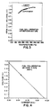
- FIGURE 2 shows the temperature and gas mixture ranges for methane/air required for fuel cell operation of the device shown in Fig. 1.
- FIGURE 3 shows a comparison of theoretical EMF versus actual EMF for a methane/air mixture for various temperatures.
- FIGURE 4 shows the load line plot of the fuel cell of Fig. 1 operated with a 9.75% methane in air mixture at 350°C.
- FIGURE 5 shows the load line plot of the fuel cell of Fig. 1 operated with a 13.8% methane in air mixture at 300°C.
- FIGURE 6 shows a perspective view of an alternate embodiment of the present invention.
- FIGURE 7 shows a comparison between the fuel cell of Fig. 1 and the fuel cell of Fig. 6 for temperature and gas mixture ranges of methane/air required for fuel cell operation.
- FIGURE 8 shows a plot of open cell EMF for the inner and outer cells of the device in Fig. 6 versus methane concentration in air at 425°C.
- FIGURE 9 shows a plot of the open cell EMF for the inner and outer cells of Fig. 6 versus ethane concentration in air at 450°C.
- FIGURE 10 shows the load line plot for the outer cell of Fig. 6 using a 33% ethane in air gas mixture at 475°C.
- Fig. 1 shows a fuel cell 10 having two partially enclosed chambers 11, 12 where the fuel gas mixture (e.g. methane/air) can enter through orifices 13 and 14.
- the fuel gas mixture e.g. methane/air
- Platinum electrodes 15, 16 are screen printed on both sides of inner wall 17.
- inner wall 17 is made of yttria stabilized zirconia, although other oxide anion conducting solid electrolytes are possible such as Mg or Ca stabilized zircon or aliovalent doped ceria and stabilized bismuth oxide.
- orifices 13, 14 are used for limiting the gas-flow, other means are possible, such as using gas permeable (porosity-controlled) material to replace the gas chambers.
- the porosity-controlled material can be solid materials such as SiO2, Al2O3 or the same electrolyte material used in the electrolyte walls.
- fuel cell 10 is exposed to a fuel gas/oxidant mixture.
- the device is heated to a temperature sufficient to raise the electrical conductivity of the zirconia to a predetermined level.
- the fuel cell operation is initiated by applying a pulse of voltage to the platinum electrodes 15, 16.
- the magnitude of the voltage pulse decreases with increasing temperature.
- the initiating pulse can be several mV and at low temperature (approximately 250°C) the pulse can be several thousand mV.
- This electrical stimulation can be eliminated if the degrees of gas-flow limitation are different between the two electrodes.
- the electrical stimulation can also be eliminated by using two metals which have different electrochemical exchange rates for the two electrodes (e.g. An Au electrode versus Pt electrode).
- Fig. 1 There is a range for both temperature and fuel concentration for which the device of Fig. 1 operates as a fuel cell.
- Fig. 2 Shown in Fig. 2 is the concentration range and temperature range for which the device in Fig. 1 operates as a fuel cell using a methane/air gas mixture. This diagram clearly shows that for a temperature greater than 450°C or a methane concentration in air of less than 7.3%, the device shown in Fig. 1 will not operate as a fuel cell.
- Fig. 3 shows that at higher temperatures (>350°C) the theoretical and actual open cell EMF are almost identical. At low temperatures, the discrepancy between actual EMF and theoretical EMF may be caused by the high internal resistance created by the slow electrodes reactions.
- Figs. 4 and 5 are current versus voltage plots of the fuel cell of Fig. 1 in operation.
- Fig. 4 shows a 9.75% methane in air fuel mixture at 350°C.
- the power obtainable from the fuel cell is the current multiplied by the voltage.
- Fig. 5 shows a 13.8% methane in air fuel mixture with the device operated at 300°C.
- Fig. 6 shows a fuel cell 60 which contains two partially enclosed chambers, an inner cell 62 and an outer cell 61.
- the fuel mixture (fuel/air or fuel/oxygen) enters the outer cell 61 through first orifice 64 and the inner cell through second orifice 65.
- Other means for gas-flow limiting control can be used such as gas permeable porosity-controlled solid material to replace the gas chambers.
- the porosity-controlled materials can be Al2, SiO2 or the same electrolyte material used in the electrolyte walls.
- the electrodes 66, 67, 68, 69 are screen printed on both sides of the two walls 70 and 71 which separate the cells 61 and 62 from the ambient fuel mixture.
- the electrodes 66, 67, 68, 69 are platinum, however, other electrical conducting material may be used and different electrode materials can be used in the same fuel cell. Examples of possible electrode material include platinum, silver, nickel, titanium, gold and palladium and mixtures thereof.
- the four electrodes 66, 67, 68, 69 are used to draw current or monitor voltage developed by operation of the fuel cell 60.
- Partition wall 72 separates the inner cell 62 and the outer cell 61.
- the walls 70 and 71 are made of 6-8% yttria stabilized zirconia although any other electrolyte material which conduct oxygens ions such as yttria doped ceria can be used.
- the partition wall 72 separating the inner and outer cells 62, 61 can be any material. In the present case the partition wall was made of 4% yttria stabilized zirconia.
- Fig. 8 presents open cell EMF measured versus methane concentration in air at 425°C from the inner and outer cells of the fuel cell of Fig. 6.
- Fig. 8 shows that the inner cell 62 operates at a lower EMF than the outer cell 61.
- Fig. 9 shows the open cell EMF for the inner and outer cells versus ethane concentration in air at 450°C.
- the inner cell results are plotted on top of the outer cell's results.
- both cells give similar EMF outputs.
- Fig. 10 shows the load line plot of the outer cell for a 33% ethane in air fuel mixture operated at 475°C.
- Fig. 9 and 10 show that it is possible to use other fuels than methane.
- Fig. 6 An important feature of the cell of Fig. 6 is that there is no requirement that an initial pulse be used to initiate fuel cell operation because the big difference in gas-flow rates between the first and second electrodes and the third and fourth electrodes. In addition, the fuel cell operating temperature and concentration requirements are extended. Both the embodiments shown in Fig. 1 and Fig. 6 do away with the need for separating the fuel and the oxidant to operate the cell.
- the power or the gas-sensing electricity will be collected between the first and second electrodes, or the third and fourth electrodes.
- the electricity can be utilized to drive electronic circuits in a remote area or to power an alarming circuit for gas leakage detection.
Landscapes
- Chemical & Material Sciences (AREA)
- Life Sciences & Earth Sciences (AREA)
- Electrochemistry (AREA)
- Chemical Kinetics & Catalysis (AREA)
- General Chemical & Material Sciences (AREA)
- Sustainable Energy (AREA)
- Sustainable Development (AREA)
- Manufacturing & Machinery (AREA)
- Engineering & Computer Science (AREA)
- Health & Medical Sciences (AREA)
- Physics & Mathematics (AREA)
- Molecular Biology (AREA)
- Analytical Chemistry (AREA)
- Biochemistry (AREA)
- General Health & Medical Sciences (AREA)
- General Physics & Mathematics (AREA)
- Immunology (AREA)
- Pathology (AREA)
- Fuel Cell (AREA)
Description
- The present invention relates to a method and apparatus for converting chemical energy to electrical energy for power usage or gas-sensing applications. More specifically, the present invention describes a fuel cell that uses a single gas mixture, such as methane and air, to achieve the spontaneous conversion of chemical energy into electrical energy.
- A fuel cell is an electrochemical device that continuously converts the chemical energy of a fuel, such as methane, and an oxidant, such as molecular oxygen, to electrical energy. The fuel and oxidant are continuously supplied to the fuel cell from an external source. The fuel and oxidant are supplied to chambers of the fuel cell which are separated by an electrolyte barrier. This electrolyte barrier can be liquid or molten electrolyte, however, the present invention is concerned with solid electrolytes.
- Since fuel cells produce power by an electrochemical reaction rather than a thermal process, they are not subject to the Carnot cycle limitation of combustion engines. This allows for a highly efficient conversion of chemical energy to electric energy. In addition, fuel cells are very clean and quiet in operation as there are no moving parts and the by products from the cell operation are carbon dioxide and water. Furthermore, it is possible to recover the waste heat generated from a fuel cell producing even greater efficiencies.
- A conventional solid-state electrolyte fuel cell uses solid non-porous metal oxide electrolyte, such as zirconium oxide as the electrolyte material. With this type of electrolyte, ionic conductivity takes place by the migration of oxygen ions through the lattice of the crystal. Typically, these zirconia cells are operated at elevated temperatures (e.g. 900°C-1000°C). Inside the conventional fuel cell the fuel and oxidation gas are required to be separated from each other by the non-porous solid electrolyte which needs two separate sets of gaseous operation equipment. The present invention solves these problems in a unique and novel manner.
- US-A-4 248 941 discloses a fuel cell operated with a fuel/oxidant mixture and the electrodes arranged side-by-side on the electrolyte with a gap in between. The electrodes are covered with a material selective to diffusion of fuel or oxidant.
- The present invention discloses a method and apparatus for generating electricity from a fuel/oxidant gas mixture for power usage or gas-sensing applications. In one aspect of the invention a fuel cell is provided which has a first solid electrolyte wall in contact with and interposed between a first electrode and a second electrode, a second solid electrolyte partition which forms a first chamber with the first solid electrolyte wall, a third solid electrolyte partition which forms a second chamber with the first solid electrolyte wall, a first gas-flow limiting means between a fuel mixture and the first chamber, a second gas-flow limiting means between the fuel mixture and the second chamber. The gas-flow limiting means can be a physical aperture or a porosity-controlled material which covers the electrode and replaces the space of the gas chamber. The chemical oxidation reaction is initiated by an electrical pulse applied to the first and second electrodes. Afterward, electricity is continuously collected at the first and second electrodes. The chemical oxidation reaction can happen spontaneously if the two gas-flow limiting means are quite different in controlling the respective rates of the gas flow.
- In an alternate aspect the fuel cell is provided with a first solid electrolyte wall in contact with and interposed between a first and a second electrode, a second solid electrolyte wall in contact with and interposed between a third and a fourth electrode, a partition wall interposed between the first and third electrodes which creates a first chamber and a second chamber, the first chamber formed by the first electrolyte wall and the partition wall and the second chamber formed by the second electrolyte wall and the partition wall. The fuel cell has a first gas-flow limiting means between the fuel/oxidant gas mixture and the first chamber and a second gas-flow limiting means between the first chamber and the second chamber positioned on the partition wall. The gas-flow limiting means can be a physical aperture or a porosity-controlled material to replace the space occupied by the gas chamber. The chemical reaction starts spontaneously if the temperature and fuel/oxidant gas mixture are within predetermined values. Electricity is collected and stored by means attached to the first and second electrodes or to the third and fourth electrodes.
- In the drawings:
- FIGURE 1 shows a perspective view of an embodiment of the present invention.
- FIGURE 2 shows the temperature and gas mixture ranges for methane/air required for fuel cell operation of the device shown in Fig. 1.
- FIGURE 3 shows a comparison of theoretical EMF versus actual EMF for a methane/air mixture for various temperatures.
- FIGURE 4 shows the load line plot of the fuel cell of Fig. 1 operated with a 9.75% methane in air mixture at 350°C.
- FIGURE 5 shows the load line plot of the fuel cell of Fig. 1 operated with a 13.8% methane in air mixture at 300°C.
- FIGURE 6 shows a perspective view of an alternate embodiment of the present invention.
- FIGURE 7 shows a comparison between the fuel cell of Fig. 1 and the fuel cell of Fig. 6 for temperature and gas mixture ranges of methane/air required for fuel cell operation.
- FIGURE 8 shows a plot of open cell EMF for the inner and outer cells of the device in Fig. 6 versus methane concentration in air at 425°C.
- FIGURE 9 shows a plot of the open cell EMF for the inner and outer cells of Fig. 6 versus ethane concentration in air at 450°C.
- FIGURE 10 shows the load line plot for the outer cell of Fig. 6 using a 33% ethane in air gas mixture at 475°C.
- A preferred embodiment of the present invention is shown in detail on Fig. 1. Fig. 1 shows a
fuel cell 10 having two partially enclosedchambers 11, 12 where the fuel gas mixture (e.g. methane/air) can enter throughorifices 13 and 14. Platinum electrodes 15, 16 are screen printed on both sides ofinner wall 17. In a preferred embodiment,inner wall 17 is made of yttria stabilized zirconia, although other oxide anion conducting solid electrolytes are possible such as Mg or Ca stabilized zircon or aliovalent doped ceria and stabilized bismuth oxide. Althoughorifices 13, 14 are used for limiting the gas-flow, other means are possible, such as using gas permeable (porosity-controlled) material to replace the gas chambers. The porosity-controlled material can be solid materials such as SiO₂, Al₂O₃ or the same electrolyte material used in the electrolyte walls. - In order to operate the present invention,
fuel cell 10 is exposed to a fuel gas/oxidant mixture. The device is heated to a temperature sufficient to raise the electrical conductivity of the zirconia to a predetermined level. The fuel cell operation is initiated by applying a pulse of voltage to the platinum electrodes 15, 16. The magnitude of the voltage pulse decreases with increasing temperature. At high temperature (approximately 400°C) the initiating pulse can be several mV and at low temperature (approximately 250°C) the pulse can be several thousand mV. This electrical stimulation can be eliminated if the degrees of gas-flow limitation are different between the two electrodes. The electrical stimulation can also be eliminated by using two metals which have different electrochemical exchange rates for the two electrodes (e.g. An Au electrode versus Pt electrode). - There is a range for both temperature and fuel concentration for which the device of Fig. 1 operates as a fuel cell. Shown in Fig. 2 is the concentration range and temperature range for which the device in Fig. 1 operates as a fuel cell using a methane/air gas mixture. This diagram clearly shows that for a temperature greater than 450°C or a methane concentration in air of less than 7.3%, the device shown in Fig. 1 will not operate as a fuel cell.
- A comparison of the open cell EMF (electromotive force or voltage) obtained from the device shown in Fig. 1 versus the theoretical EMF (thermodynamic value) is shown in Fig. 3.
- Fig. 3 shows that at higher temperatures (>350°C) the theoretical and actual open cell EMF are almost identical. At low temperatures, the discrepancy between actual EMF and theoretical EMF may be caused by the high internal resistance created by the slow electrodes reactions.
- Shown in Figs. 4 and 5 are current versus voltage plots of the fuel cell of Fig. 1 in operation. Fig. 4 shows a 9.75% methane in air fuel mixture at 350°C. The power obtainable from the fuel cell is the current multiplied by the voltage. A similar diagram is shown in Fig. 5 for a 13.8% methane in air fuel mixture with the device operated at 300°C.
- Although, only methane mixture is used here, the fuel type is not limited so. It can be any reducing gas such as H₂, CO, alkanes or alkenes. An alternate embodiment of the fuel cell of the present invention is shown in Fig. 6. Fig. 6 shows a
fuel cell 60 which contains two partially enclosed chambers, an inner cell 62 and an outer cell 61. The fuel mixture (fuel/air or fuel/oxygen) enters the outer cell 61 through first orifice 64 and the inner cell through second orifice 65. Other means for gas-flow limiting control can be used such as gas permeable porosity-controlled solid material to replace the gas chambers. The porosity-controlled materials can be Al₂, SiO₂ or the same electrolyte material used in the electrolyte walls. The electrodes 66, 67, 68, 69 are screen printed on both sides of the twowalls 70 and 71 which separate the cells 61 and 62 from the ambient fuel mixture. In a preferred embodiment the electrodes 66, 67, 68, 69 are platinum, however, other electrical conducting material may be used and different electrode materials can be used in the same fuel cell. Examples of possible electrode material include platinum, silver, nickel, titanium, gold and palladium and mixtures thereof. The four electrodes 66, 67, 68, 69 are used to draw current or monitor voltage developed by operation of thefuel cell 60. Partition wall 72 separates the inner cell 62 and the outer cell 61. - In the tests run on the
fuel cell 60, thewalls 70 and 71 are made of 6-8% yttria stabilized zirconia although any other electrolyte material which conduct oxygens ions such as yttria doped ceria can be used. The partition wall 72 separating the inner and outer cells 62, 61 can be any material. In the present case the partition wall was made of 4% yttria stabilized zirconia. - Substantial improvements in results are obtained from using the device in Fig. 6 than the device in Fig. 1. Initially the device is heated to a temperature where the solid zirconia electrolyte has a predetermined ionic conductivity. Shown in Fig. 7 is the improvement in operating conditions from the fuel cell in Fig. 6 over the fuel cell in Fig. 1. With the fuel cell in Fig. 6 it is possible to operate at temperatures approaching 600°C and the methane concentration in air can be as low as 7.3%.
- Fig. 8 presents open cell EMF measured versus methane concentration in air at 425°C from the inner and outer cells of the fuel cell of Fig. 6. Fig. 8 shows that the inner cell 62 operates at a lower EMF than the outer cell 61.
- An ethane gas/air fuel mixture was used in the cell of Fig. 6 and the results are shown in Fig. 9 and 10. Fig. 9 shows the open cell EMF for the inner and outer cells versus ethane concentration in air at 450°C. For clarity of the figures, the inner cell results are plotted on top of the outer cell's results. As shown in Fig. 9, both cells give similar EMF outputs. Fig. 10 shows the load line plot of the outer cell for a 33% ethane in air fuel mixture operated at 475°C. Fig. 9 and 10 show that it is possible to use other fuels than methane.
- An important feature of the cell of Fig. 6 is that there is no requirement that an initial pulse be used to initiate fuel cell operation because the big difference in gas-flow rates between the first and second electrodes and the third and fourth electrodes. In addition, the fuel cell operating temperature and concentration requirements are extended. Both the embodiments shown in Fig. 1 and Fig. 6 do away with the need for separating the fuel and the oxidant to operate the cell.
- The power or the gas-sensing electricity will be collected between the first and second electrodes, or the third and fourth electrodes. The electricity can be utilized to drive electronic circuits in a remote area or to power an alarming circuit for gas leakage detection.
Claims (22)
- A fuel cell for generating electricity or gas-sensing in a fuel-oxidant gas mixture comprising
a first solid electrolyte wall in contact with and interposed between a first electrode and a second electrode;
a second solid electrolyte partition which forms a first chamber with said first solid electrolyte wall;
a third solid electrolyte partition which forms a second chamber with said first solid electrolyte wall;
a first gas-flow limiting means between a fuel mixture and said first chamber;
a second gas-flow limiting means between the fuel mixture and said second chamber; and
a fuel-oxidant gas mixture to which the first electrodes and the second electrodes are exposed; and
means to collect and store energy generated from the electrochemical reaction between the first and the second electrodes. - The fuel cell of claim 1 wherein said first solid electrolyte wall is made of an oxide electrolyte.
- The fuel cell of claim 2 wherein the oxide electrolyte comprises yttria or calcia stabilized zirconia.
- The fuel cell of claim 1 wherein said first and said second gas-flow limiting means comprise a porosity-controlled solid material.
- The fuel cell of claim 4 wherein the porosity-controlled solid material is made of alumina or silica.
- The fuel cell of claim 1 wherein the fuel oxidant mixture comprises at least 8.75% methane in air.
- The fuel cell of claim 1 wherein said first and said second electrodes are selected from the group consisting of platinum, silver, nickel, titanium, gold, and palladium and mixtures thereof.
- The fuel cell of claim 1 further comprising means to initiate an electrochemical reaction in the fuel mixture, said means connected to said first and second electrodes.
- A fuel cell for generating electricity in a fuel/oxidant gas mixture comprising
a first solid electrolyte wall in contact with and interposed between a first and a second electrode;
a second solid electrolyte wall in contact with and interposed between a third and a fourth electrode;
a partition wall interposed between said first and third electrodes which creates a first chamber and a second chamber, said first chamber formed by said first electrolyte wall and said partition wall and said second chamber formed by said second electrolyte wall and said partition wall;
a first gas-flow limiting means between the fuel/oxidant gas mixture and said first chamber;
a second gas-flow limiting means between said first chamber and said second chamber position on said partition wall; and
means for collecting and storing energy from the first and second electrodes or the third and fourth electrodes;
wherein an electrochemical reaction spontaneously occurs between the fuel/oxidant gas mixture. - The fuel cell of claim 9 wherein said first and second electrolyte wall are made of an oxide electrolyte.
- The fuel cell of claim 10 wherein the oxide electrolyte comprises yttria or calcia stabilized zirconia.
- The fuel cell of claim 9 wherein said first and said second gas-flow limiting means comprises a porosity-controlled solid material.
- The fuel cell of claim 12 wherein the porosity-controlled solid material is made of alumina or silica.
- The fuel cell of claim 9 wherein said partition wall is made of yttria or calcia partially stabilized zirconia.
- The fuel cell of claim 9 wherein the fuel/oxidant mixture comprises at least 8.75% methane in air.
- The fuel cell according to claim 9 wherein said first, second, third, and fourth electrodes are selected from the group consisting of platinum, silver, nickel, titanium, palladium and mixtures thereof.
- A method of generating electricity from a fuel/oxidant gas mixture or sensing gas of a fuel/oxidant gas mixture comprising:
providing a fuel cell having a first solid electrolyte wall in contact with and interposed between a first electrode and a second electrode and a second solid electrolyte wall in contact with and interposed between a third electrode and a fourth electrode, said second and fourth electrodes in communication with the fuel/oxidant gas mixture, a partition wall interposed between said first and third electrodes which creates a first chamber and a second chamber, said fuel cell having a first gas flow limiting means between the fuel/oxidant gas mixture and the first chamber and a second gas flow limiting means between the first chamber and the second chamber;
collecting and storing electricity generated from said first and second electrodes and from said third and fourth electrodes. - The method of claim 17 wherein said first and second electrolyte wall is made of an oxide electrolyte material/ zirconia.
- The method of claim 17 wherein the first and second gas flow limiting means comprises a porosity-controlled material.
- A method of generating electricity from a fuel/oxidant gas mixture comprising:
providing a fuel cell having a first solid electrolyte wall in contact with and interposed between a first electrode and a second electrode;
a second solid electrolyte partition which forms a first chamber with said first solid electrolyte wall, a third solid electrolyte partition which forms a second chamber with said first electrolyte wall, and fuel cell having a first gas flow limiting means between said first chamber and a fuel/oxidant gas mixture and a second gas flow limiting means between said second chamber and the fuel gas/oxidant mixture;
providing a means to initiate an electrical pulse between said first and second electrodes;
collecting and storing electricity generated from said first and second electrodes. - The method according to claim 20 wherein said first electrolyte wall, said second electrolyte partition and said third electrolyte partition are all made of an oxide electrolyte materials.
- The method according to claim 20 wherein the first and second gas flow limiting means comprises a porosity-controlled material.
Applications Claiming Priority (2)
| Application Number | Priority Date | Filing Date | Title |
|---|---|---|---|
| US490812 | 1990-03-08 | ||
| US07/490,812 US5100742A (en) | 1990-03-08 | 1990-03-08 | Method and device for gaseous fuel cell operation |
Publications (3)
| Publication Number | Publication Date |
|---|---|
| EP0445597A2 EP0445597A2 (en) | 1991-09-11 |
| EP0445597A3 EP0445597A3 (en) | 1993-04-14 |
| EP0445597B1 true EP0445597B1 (en) | 1995-06-07 |
Family
ID=23949567
Family Applications (1)
| Application Number | Title | Priority Date | Filing Date |
|---|---|---|---|
| EP91102546A Expired - Lifetime EP0445597B1 (en) | 1990-03-08 | 1991-02-21 | Method and device for gaseous fuel cell operation |
Country Status (5)
| Country | Link |
|---|---|
| US (1) | US5100742A (en) |
| EP (1) | EP0445597B1 (en) |
| JP (1) | JPH04220953A (en) |
| CA (1) | CA2037031A1 (en) |
| DE (1) | DE69110153T2 (en) |
Families Citing this family (7)
| Publication number | Priority date | Publication date | Assignee | Title |
|---|---|---|---|---|
| GB9412073D0 (en) * | 1994-06-16 | 1994-08-03 | British Gas Plc | Method of operating a fuel cell |
| CN100431214C (en) * | 2000-03-24 | 2008-11-05 | Cmr燃料电池(英国)有限公司 | Mixed reactant fuel cell with porous electrodes with overflow channels |
| GB0007306D0 (en) * | 2000-03-24 | 2000-05-17 | Scient Generics Ltd | Concept for a compact mixed-reactant fuel cell or battery |
| WO2003028131A2 (en) * | 2001-08-29 | 2003-04-03 | Forschungszentrum Jülich GmbH | Fuel cell, fuel cell stack and an operating method for the same |
| JP3860733B2 (en) | 2001-09-17 | 2006-12-20 | 新光電気工業株式会社 | Fuel cell |
| US7014929B2 (en) * | 2003-01-23 | 2006-03-21 | Hewlett-Packard Development Company, L.P. | Fuel cell |
| WO2006014190A1 (en) * | 2004-03-16 | 2006-02-09 | The Regents Of The University Of California | Compact fuel cell |
Family Cites Families (10)
| Publication number | Priority date | Publication date | Assignee | Title |
|---|---|---|---|---|
| NL6413003A (en) * | 1964-11-07 | 1966-05-09 | ||
| US4248941A (en) * | 1979-12-26 | 1981-02-03 | United Tecnologies Corporation | Solid electrolyte electrochemical cell |
| US4476198A (en) * | 1983-10-12 | 1984-10-09 | The United States Of America As Represented By The United States Department Of Energy | Solid oxide fuel cell having monolithic core |
| JPS6086457A (en) * | 1983-10-19 | 1985-05-16 | Hitachi Ltd | Air fuel ratio sensor for controlling engine |
| JPS62182645A (en) * | 1985-12-26 | 1987-08-11 | Honda Motor Co Ltd | Method for controlling oxygen concentration sensor |
| JPH073405B2 (en) * | 1986-03-27 | 1995-01-18 | 本田技研工業株式会社 | Abnormality detection method for oxygen concentration sensor |
| CA1276972C (en) * | 1986-10-22 | 1990-11-27 | David S. Strong | Multi-cell metal/air battery |
| US4791035A (en) * | 1987-12-10 | 1988-12-13 | Westinghouse Electric Corp. | Cell and current collector felt arrangement for solid oxide electrochemical cell combinations |
| US4883497A (en) * | 1988-03-28 | 1989-11-28 | Arch Development Corporation | Formation of thin walled ceramic solid oxide fuel cells |
| US4863813A (en) * | 1988-09-15 | 1989-09-05 | Bell Communications Research, Inc. | Primary source of electrical energy using a mixture of fuel and oxidizer |
-
1990
- 1990-03-08 US US07/490,812 patent/US5100742A/en not_active Expired - Lifetime
-
1991
- 1991-02-21 EP EP91102546A patent/EP0445597B1/en not_active Expired - Lifetime
- 1991-02-21 DE DE69110153T patent/DE69110153T2/en not_active Expired - Fee Related
- 1991-02-25 CA CA002037031A patent/CA2037031A1/en not_active Abandoned
- 1991-03-07 JP JP3065230A patent/JPH04220953A/en not_active Withdrawn
Also Published As
| Publication number | Publication date |
|---|---|
| CA2037031A1 (en) | 1991-09-09 |
| US5100742A (en) | 1992-03-31 |
| EP0445597A2 (en) | 1991-09-11 |
| JPH04220953A (en) | 1992-08-11 |
| DE69110153D1 (en) | 1995-07-13 |
| DE69110153T2 (en) | 1995-10-19 |
| EP0445597A3 (en) | 1993-04-14 |
Similar Documents
| Publication | Publication Date | Title |
|---|---|---|
| USRE28792E (en) | Electrochemical method for separating O2 from a gas; generating electricity; measuring O2 partial pressure; and fuel cell | |
| EP0188056B1 (en) | High temperature solid electrolyte electrochemical cells | |
| US3400054A (en) | Electrochemical method for separating o2 from a gas; generating electricity; measuring o2 partial pressure; and fuel cell | |
| US5770326A (en) | Monolithic mass and energy transfer cell | |
| Doenitz et al. | Hydrogen production by high temperature electrolysis of water vapour | |
| EP1309027B1 (en) | Fuel cell | |
| US7659021B2 (en) | Power generating apparatus using solid oxide fuel cell | |
| US5124021A (en) | Solid electrolyte gas sensor and method of measuring concentration of gas to be detected in gas mixture | |
| US20040076868A1 (en) | Fuel cell and method for forming | |
| JPH11335164A (en) | Oxide ion conductor and its use | |
| JPH0997613A (en) | High temperature electrochemical cell | |
| JPH0159705B2 (en) | ||
| CA2211391A1 (en) | An electrochemical energy conversion and storage system | |
| Tillement | Solid state ionics electrochemical devices | |
| US5976721A (en) | Chemical cogeneration process | |
| JP2007197315A (en) | Mixed ionic conductor and device using the same | |
| US5100742A (en) | Method and device for gaseous fuel cell operation | |
| US3432352A (en) | High temperature fuel cell having a palladium film between the anode and electrolyte | |
| JP2009209441A (en) | Electrochemical cell | |
| JP4633531B2 (en) | Electrical joining structure and joining method of solid oxide fuel cell stack | |
| KR101395528B1 (en) | Generator | |
| Kharton et al. | Testing tubular solid oxide fuel cells in nonsteady-state conditions | |
| EP0639866B1 (en) | Stable air electrode for high temperature solid oxide electrolyte electrochemical cells | |
| US20050048352A1 (en) | Fuel-cell device utilizing surface-migration on solid oxide | |
| JP2001148251A (en) | Solid electrolyte and fuel cell using the same |
Legal Events
| Date | Code | Title | Description |
|---|---|---|---|
| PUAI | Public reference made under article 153(3) epc to a published international application that has entered the european phase |
Free format text: ORIGINAL CODE: 0009012 |
|
| AK | Designated contracting states |
Kind code of ref document: A2 Designated state(s): DE FR GB IT |
|
| PUAL | Search report despatched |
Free format text: ORIGINAL CODE: 0009013 |
|
| AK | Designated contracting states |
Kind code of ref document: A3 Designated state(s): DE FR GB IT |
|
| 17P | Request for examination filed |
Effective date: 19930924 |
|
| 17Q | First examination report despatched |
Effective date: 19940726 |
|
| GRAA | (expected) grant |
Free format text: ORIGINAL CODE: 0009210 |
|
| AK | Designated contracting states |
Kind code of ref document: B1 Designated state(s): DE FR GB IT |
|
| ET | Fr: translation filed | ||
| REF | Corresponds to: |
Ref document number: 69110153 Country of ref document: DE Date of ref document: 19950713 |
|
| ITF | It: translation for a ep patent filed | ||
| PG25 | Lapsed in a contracting state [announced via postgrant information from national office to epo] |
Ref country code: GB Effective date: 19960221 |
|
| PLBE | No opposition filed within time limit |
Free format text: ORIGINAL CODE: 0009261 |
|
| STAA | Information on the status of an ep patent application or granted ep patent |
Free format text: STATUS: NO OPPOSITION FILED WITHIN TIME LIMIT |
|
| 26N | No opposition filed | ||
| GBPC | Gb: european patent ceased through non-payment of renewal fee |
Effective date: 19960221 |
|
| PG25 | Lapsed in a contracting state [announced via postgrant information from national office to epo] |
Ref country code: FR Effective date: 19961031 |
|
| PG25 | Lapsed in a contracting state [announced via postgrant information from national office to epo] |
Ref country code: DE Effective date: 19961101 |
|
| REG | Reference to a national code |
Ref country code: FR Ref legal event code: ST |
|
| PG25 | Lapsed in a contracting state [announced via postgrant information from national office to epo] |
Ref country code: IT Free format text: LAPSE BECAUSE OF NON-PAYMENT OF DUE FEES;WARNING: LAPSES OF ITALIAN PATENTS WITH EFFECTIVE DATE BEFORE 2007 MAY HAVE OCCURRED AT ANY TIME BEFORE 2007. THE CORRECT EFFECTIVE DATE MAY BE DIFFERENT FROM THE ONE RECORDED. Effective date: 20050221 |