-
The invention relates to an image processor for producing anti-aliased images.
-
There are a number of different types of aliasing effects which appear in images. Staircase aliasing is the effect which can be observed on lines and edges which are at an angle to the horizontal and vertical directions on a pixel-based display such as a raster-scanned visual display device or a matrix printer. This invention is directed to reducing staircase aliasing and does not specifically address other aliasing problems such as the Moire patterns associated with sampling aliasing.
-
Anti-aliasing is a technique which reduces this effect as perceived when viewing the displayed image by adjusting the intensity of the displayed pixels along the line or edge. It has been proposed to perform anti-aliasing at various times and in various ways during the generation of the images for display.
-
Where an image is the result of some rendering process, such as the creation of two-dimensional views of a three-dimensional object in a solid modelling system, the anti-aliasing can be performed on each edge and/or line as it is generated. Anti-aliasing in this manner can be termed pre-filtering. This can be performed by a technique termed "supersampling", where extra values are calculated and then averaged. This and other pre-filtering approaches, are, however, expensive in terms of processing time.
-
It has also been suggested to perform anti-aliasing after an image has been created by convolution filtering. Anti-aliasing after an image has been created can be termed post-filtering. This technique has the disadvantage, however, of blurring the image too much with the result that even horizontal and vertical lines become blurred.
-
There is a need, therefore, for another approach to the anti-aliasing of images which is not as expensive as pre-filtering, yet produces better results than convolution filtering. The object of the invention is to fulfil this need.
-
In accordance with the invention there is provided an image processor for processing pixel data defining an image and comprising image processing logic for detecting pixel data representing stepped chrominance and/or luminance transitions characteristic of staircase aliasing in the image and for producing an output image including anti-aliasing on the detected stepped transitions.
-
By only performing anti-aliasing on transitions (edges) which it has detected as manifesting staircasing, an image processor in accordance with the invention is able to give much better results than can be achieved with conventional convolution filtering while still performing post processing of a source image.
-
Preferably the image processing logic comprises staircase point detection logic for detecting a staircase point at which there is step in a chrominance and/or luminance transition from a first or a second side of a line of pixels to the opposing side of the line of pixels, where the line of pixels is a row or a column of image pixels. There are four possible types of steps in the transition since the crossing can be from a first or a second side of a line to the opposing side and the line of pixels can be a row or column.
-
In order to detect steps in the transitions of all four types, the image processing logic preferably scans the image four times, in each scan a test being made for a different type of staircase point. However, the image processing logic can alternatively treat each pixel position in turn, testing for the four different types of staircase point at each pixel position.
-
The image processing logic preferably comprises staircase segment logic for finding the far end of first and second staircase segments starting at the staircase point detected by the staircase point detection logic; the staircase segment logic locating the end of a first staircase segment by testing for the position in a first direction along the line of pixels at which the transition ceases to be adjacent said opposing side of the line of pixels and testing for the position in the opposite direction along the line of pixels at which the transition ceases to be adjacent said one side of the line of pixels. Separate logic for the first and second segments can be provided, or common logic can be provided which receives appropriate input information.
-
The image processing logic comprises image modification logic for testing for predetermined conditions at the end of a staircase segment and for modifying pixel data in accordance with the predetermined condition detected for the staircase segment. The predetermined conditions tested for are that:
- (a) the transition steps across a further line of pixels;
- (b) the transition steps back across the line of pixels; and
- (c) neither (a) nor (b).
-
Preferably, the image processor comprises source image storage for a source image and output image storage for the output image and performs an initial operation of copying the source image from the source image storage to the output image storage, then tests the source image in the source image storage to detect pixel data representing stepped chrominance and/or luminance transitions characteristic of staircase aliasing and modifies data accordingly in the output image storage to produce the output image including anti-aliasing on the detected stepped transitions.
-
The tasks to be performed by the image processing logic are suitable for a parallel processing implementation. This can be achieved by the use of suitable parallel processing hardware. The invention is also suitable for implementation in a data processing system such as conventional computer workstation or intelligent graphics adapter by the provision of appropriate software.
-
An embodiment of the present invention is described hereinafter with reference to the accompanying drawings in which:
- Figure 1 is an example of a image processing system in the form of a computer workstation;
- Figure 2 is a schematic illustrating features of one embodiment of the invention;
- Figure 3 represents a block of pixels forming part of an image manifesting staircase aliasing;
- Figure 4 is an overview of logic for selective anti-aliasing of an image;
- Figure 5 represents a number of different patterns for scanning an image and the transition steps thus detected;
- Figure 6 represents part of an image used for explaining the detection of a staircase point in an image;
- Figure 7 represents part of an image used for explaining the detection of a staircase segment adjacent a staircase point in the image scanning direction;
- Figures 8A and 8B represent a part of an image before and after modification for a first type of staircase segment;
- Figures 9A and 9B represent a part of an image before and after modification for a second type of staircase segment;
- Figures 10A and 10B represent a part of an image before and after modification for a third type of staircase segment; and
- Figure 11 represents part of an image used for explaining the detection of a staircase segment adjacent a staircase point in the opposite direction to the image scanning direction.
-
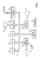
Figure 1 illustrates a typical hardware configuration of a workstation with a central processing unit 10 (eg. a conventional microprocessor) and a number of other units interconnected via a system bus 12. The workstation shown in Figure 1 includes a random access memory RAM 14, a read only store 16, an I/O adapter 18 for connecting peripheral devices such as disk units 20 to the bus, a user interface adapter 22 for connecting a keyboard 24 and/or a mouse 26 and/or other user interface devices (eg. a touch screen controller, not shown) to the bus, a communications adapter 28 for connecting the workstation to a data processing network a display adapter 30 for connecting the bus to a display device 32 (eg. a CRT monitor) and a printer adapter 34 for connecting the bus to a printing device 36.
-
The present invention can be implemented on a workstation as shown in Figure 1 by the provision of appropriate image processing logic as will be described hereinafter. It should be noted that Figure 1 illustrates only one example of a hardware configuration suitable for implementing the invention. The hardware of the workstation can be adapted to perform specific tasks as required. For example, a television camera may be connected into the system via the display adapter, or otherwise as appropriate, as an image capture device. No details of such further features are given as they are not crucial to the present invention. The invention could equally well be implemented on a mainframe data processing system.
-
Figure 2 is a schematic illustrating that image processing logic 40 receives pixel data for an image to be rendered from source image storage 42 and outputs the processed image data to an output image storage 44.
-
In the preferred embodiment the source image storage 40 and the output image storage are first and second sets, respectively of locations in the workstation RAM 14. The image processing logic 40 is provided by suitable implementing software which is also stored, in use, in the workstation RAM and is used to control the operation of the workstation. The input image will have been derived from an image generator and stored in the source storage. How the image is generated is not important here, except to say that it is assumed that the source image contains edges manifesting staircase aliasing.
-
In the preferred embodiment, the output image storage 44 is a second set of locations in the workstation RAM 14.
-
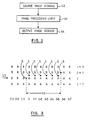
Figure 3 illustrates a block of pixels forming part of an image. Each letter "A", or "B" represents a pixel, not a displayed character symbol. The pixels are assumed to have one of two colours "A" or "B" in Figure 3. It should be noted that the image may contain pixels having many more colours and/or intensities. For ease of explanation, let us assume that the colour "A" relates to a first area and the colour "B" to a second area. The transition between the area "A" and the area "B" forms a stepped transition between those areas representing an edge which is neither horizontal nor vertical, but lies at an angle. The image has not been anti-aliased as a step-like edge can be clearly seen.
-
The points indicated "Q" and "R" are said to be staircase points. A staircase point is a point where the transition, or edge, between the areas which is generally angled in a first direction (here the line is approximately horizontal) moves one pixel line in the orthogonal direction (here vertically). A staircase point is defined between pixels, not centred on a pixel, in a given pixel row or column. In Figure 3, there is a staircase point "Q" in the row "J" and a staircase point "R" in the row J+1. There are four different types of staircase points. The four types, two of which occur in rows and two of which occur in columns, are illustrated in Figure 5 and described below.
-
The points labelled "S" form what is termed a staircase segment "SS" and is defined as the segment of an edge between one staircase point and the next. The staircase segment lies between two rows or columns (here between the rows "J" and "J+1") depending on whether the edge is nearer to being horizontal or vertical.
-
Figure 4 illustrates logic for analysing the image in the source storage in order to detect edges such as that shown in Figure 3 and to store a modified version of the image in the output storage. The effect of the processing is to produce a modified image in which the staircasing effect has been reduced by selective anti-aliasing.
-
The image processing logic operates by firstly copying (50) the input image from the input storage (42) to the output storage (44), then completely scanning the image in the input storage four times (S1, S2, S3, S4) and updating the output image on detection of each staircase edge segment. Each of the four scans through the input image takes the pixels in a different order and applies a test for a different type of staircase point. When a staircase point is detected, the image processing logic tests how long the staircase segment is either side of the staircase point in the current line (row or column) of pixels and modifies the output image data depending on the type of staircase segment detected. In this way, by the end of the fourth scan, all staircase segments in the source image are detected and the corresponding data in the output image modified appropriately.
-
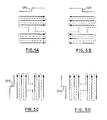
Figure 5 represents the scan directions for the present example of the invention. The first scan (Figure 5A) starts in the bottom left hand corner of the image, and scans each row of the image in turn progressing up the image, with the rows being scanned from left to right. The line SP1 over the image array in Figure 5A represents the shape of the transition tested for in the first scan, this shape of transition forms the first type of staircase point and corresponds to the shape of transition at the point Q in Figures 3 and 6. The second scan (Figure 5B) then starts from the bottom right of the image and scans each row in turn progressing up the image with each row being scanned from right to left. The line SP2 over the image array in Figure 5B represents the shape of the transition tested for in the second scan, this shape of transition forming the second type of staircase point. The third scan (Figure 5C) starts from the bottom left of the image and scans each column of the image progressing from left to right, with each column being scanned from bottom to top. The line SP3 to the left of the image array in Figure 5C represents the shape of the transition tested for in the third scan, this shape of transition forming the third type of staircase point. The fourth scan (Figure 4D) starts from the bottom right of the image and scans each column progressing from right to left across the image with each column being scanned from bottom to top. The line SP4 to the left of the image array in Figure 5D represents the shape of the transition tested for in the fourth scan, this shape of transition forming the fourth type of staircase point.
-
It will be apparent from the following however, that different scanning directions and/or a different order of performing the scans could be used to successfully identify and modify all the staircase segments in the source image.
-
Returning to Figure 4, the logic starts (50) by copying the image from the source (42) to the destination storage (44). In the following, it is assumed that the image is stored in memory as a two dimensional array of pixels. Although the image will normally be representative of a rectangular array of image pixels, the data defining the pixels may be stored in any appropriate data structure, for example as a series of lists or linked lists as will be apparent to one skilled in the art. The image processing logic includes and/or is able to control appropriate addressing logic for accessing the data for pixels at desired row and column locations within the array in a conventional manner.
-
The image processing logic starts the first image scan (52, S1) and staircase point detection logic (54) tests successive pixels in turn for a staircase point. A staircase point is detected for a row J between a pixel (P(J,I-1)) at column (I-1) and a pixel (P(J,I)) at column (I) when the following condition C1 is satisfied:
-
An example of this condition is illustrated in Figure 6 where P(J,I) and P(J-1,I-1) have the values "A0" and "A1" and P(J+1,I) and P(J,I-1) have the values "B0" and "B1" respectively. It should be noted that the function "SAME" used in the above condition need not mean exact equality. Indeed, in view of the vast range of different chrominance and luminance values which may be specified in an image, it is preferable that "SAME" is defined such that positive result is obtained when the pixels being compared differ by an amount which will be determined to be acceptable in a given case, eg. by trial and error. In the case of a grey scale (monochrome) image, SAME detects a given intensity difference threshold. In a multicolour image, it detects a given intensity difference threshold in any of the colours (usually the red, green, blue primary colours) specified in the image. "NOTSAME" gives a positive result for those cases where a negative result would be obtained from the function "SAME".
-
If the staircase point detection logic 54 finds no staircase point for a given pixel, and pixels remain for the current scan (64), then the next pixel to be scanned in the scan direction SD is selected and the staircase point detection logic 54 applies the condition C1 for this next pixel.
-
If the staircase
point detection logic 54 does find a staircase point, then first
staircase segment logic 56 tests for the length of the staircase segment adjacent to the staircase segment in the scan direction SD. This is done by further scanning along the line of pixels from pixel position I in the scanning direction SD and, at each pixel position, testing whether the following condition C2 is satisfied:
where i + 1, 2, 3, .. for successive pixels.
-
Figure 7 illustrates a block of pixels forming part of an image with the boundary labelled C2 indicating the pixels tested for i = 3. The first staircase segment logic 56 continues to increment the value of "i" until the condition C2 is no longer satisfied or the end of the current scan line is reached. The point where the condition C2 ceases to be satisfied is determined to be the end of a staircase segment (compare point "R", Figure 2). In this case, the first staircase segment logic 56 passes the number of pixels scanned and the location of the starting and finishing locations of the staircase segment to first image modification logic 58 for modifying the output image storage to remove the staircasing effect.
-
There are three cases which can occur at the end of a staircase segment. The modification which is performed to the pixel data in the output image depends on the case which is detected at the end of the segment.
-
In order to determine which of these three cases exists, the first image modification logic 58 tests to see which case applies and then modifies the data at appropriate locations in the output image.
-
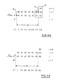
One of the three cases tested for is where the edge between the areas in the image continues in the same general direction as before. An example of this is illustrated in Figure 8A. The staircase segment in Figure 8A extends between the staircase points "Q" and "R".
-
The first
staircase segment logic 58 tests whether the following condition C3 is met for the point at the end of the segment:
where k is the number of pixels (in Figure 8A, 6 pixels) stepped in the scanning direction by the
logic 56 until the condition C2 ceased to be satisfied.
-
If the condition C3 is satisfied then replacements are made to the pixel data at the locations in the output storage corresponding to the pixels in the first half (in the scanning direction) of the segment ss. Figure 8B represents the part of the image illustrated in Figure 8A as modified by the
image modification logic 58, where:
-
The denominators in the above expressions (here 12) are derived as 2*k (i.e. two times the number of pixels stepped by the logic 56) and the multiplicators for the numerators are determined as a smooth function based on the denominator. In particular, in the above case:
-
The result of the above modifications is to set the chrominance and/or luminance values for the modified pixels at particular values between those of the pixels adjacent each side of the transition at that position in the source image. It should be noted that the pixel values for B3, B4 and B5 will be modified by the second image modification logic 62 when this staircase segment SS is detected, during the processing of the next row (J+1), by the second staircase segment logic 60 following detection of the staircase point "R" by the staircase point detection logic 54.
-
The second of the three cases tested for is where the edge between the areas in the image turns to form part of an arc. An example of this is illustrated in Figure 9A. The staircase segment in Figure 9A extends between the staircase points "Q" and "R".
-
The first
image modification logic 58 tests whether the following condition C4 is met for the point at the end of the segment:
where k is once more, the number of pixels (in Figure 9A, 6 pixels) stepped in the scanning direction by the
logic 56 until the condition C2 ceased to be satisfied.
-
If the condition C4 is satisfied then it is assumed that the edge traces an arc which can be divided into three sub-segments Q-L, L-M, M-R - see Figure 9A. The pixel data is then modified at locations in the output storage corresponding to the pixels in the first of these three sub-segments Q-L. Figure 9B represents the part of the image illustrated in Figure 9a as modified by the first
image modification logic 58, where:
-
The general equation for ai can readily be determined from the above example. It should be noted that A4 and A5 will be modified independently when the point "R" is located as a staircase point during the second full scan of the image.
-
The third case is where neither condition C3, nor condition C4 has been satisfied. This can occur where the edge of the image was encountered during scanning along the staircase segment, where the areas A and B merge into one another, or where another edge breaks in. In this case the edge is assumed to lie on a line (not shown) joining "Q" and "E". Figure 10A represents this condition.
-
Where neither condition C3 nor condition C4 are identified, the first
image modification logic 58 makes the assumption the end of the segment is midway between the point "Q" and the next staircase point and modifies the pixel data at locations corresponding to all of the points in the current scan line from "Q" to "E". Figure 10B represents the portion of the image represented in Figure 10A as modified by the
image modification logic 58, where:
-
The denominators in the above expressions (here 24) are derived as 4*k (i.e. two times the number of pixels stepped by the logic 56) and the multiplicators for the numerators are determined as a smooth function based on the denominator. This function can readily be determined from the above example.
-
When the first
image modification logic 58 has modified the pixel data in the output storage for the current line segment, the second staircase
segment detection logic 60 tests for the length of the staircase segment adjacent to the staircase segment in direction SD' opposite to the scan direction SD. This is done by scanning back along along the line of pixels in the direction SD' from pixel position I and, at each pixel position, testing whether the following condition C5 is satisfied:
where i = 2, 3, 4, . for successive pixels.
-
Figure 11 illustrates a block of pixels forming part of an image with the boundary labelled C5 indicating the pixels tested for i = 2. The second staircase segment detection logic 60 continues to increment the value of "i" until the condition C5 is no longer satisfied or the beginning of the current scan line is reached. The point where the condition C5 ceases to be satisfied is determined to be the the end of a staircase segment. In this case, the second staircase segment detection logic 56 passes the number of pixels scanned and the location of the starting and finishing locations of the staircase segment to second image modification logic 60 for modifying the output image storage to remove the staircasing effect.
-
As with the first image modification logic, the second image modification logic detects one of three possible cases:
- 1) the transition in the image continues in the same general direction (compare Figures 8A and 8B);
- 2) the transition in the image traces an arc (compare Figures 9A and 9B);
- 3) neither of the above (e.g. the edge of the image was encountered during scanning back along the staircase segment, the areas A and B merge into one another, or another edge breaks in).
-
The second image modification logic 62 detects these cases by testing for conditions comparable to those described with reference to Figures 8A, 8B, 9A, 9B, 10A and 10B, but modified to take account of the opposed scanning direction. The conditions used are not described herein but can be readily derived from the conditions C3 and C4 above after comparison of the differences between conditions C2 and C5. Similarly, the modifications performed on the image in the output storage by the second image modification logic 62 in response to the detection of these conditions being met can be derived readily from the description of the equivalent cases for the scanning direction SD.
-
When the second image modification logic 62 has modified the pixel data in the output storage for the current line segment, or in the case when the second staircase segment detection logic 56 did not detect a staircase segment in the scan direction, the processing is continued for the next pixel to be considered in the scanning direction SD.
-
When the last pixel in first full scan has been reached, the image processing logic starts 68 the second full scan of the image in the input storage and modifies the image in the output storage by second scan logic S2 corresponding generally to the first scanning logic S1. The second scanning logic S2 only differs in so far as to take account of the different scanning order. The details of the second scanning logic are not described as they can be derived readily from what has already been described above.
-
The same applies for the third full scan (70, S3) and the fourth full scan (72, S4) of the image. On completion of the fourth full scan, all the stepped transitions in the source image will have been anti-aliased in the output image.
-
Although a specific example of the invention are described herein, the invention is not limited thereto and many modifications and alterations are possible.
-
For example, although a preferred implementation of the invention is described in which the source image storage 40 and the output image storage are first and second sets, respectively of locations in the workstation RAM 14 and the image processing logic 40 is provided by suitable implementing software which is also stored, in use, in the workstation RAM, this need not be the case. One or both of the image stores may be provided by special purpose storage, for example, the output storage may be a display buffer used directly for driving a display device. Also, the image processing logic may be provided by special purpose hardware. For example, the image processing logic may be provided by an array of special purpose processing elements, or by a programmable logic array, or any other suitable hardware means.
-
Also, although a particular set of scan directions are described, it will be appreciated that the array may be scanned in different combination of directions and/or in a different order and still detect all the stepped transitions to be anti-aliased.
-
In the above example, the image processing logic scans the image array four times, each time in a different pixel order. In each scan a test is applied to identify a particular type of staircase point. When a staircase point is detected, the length and type of staircase segment to each side of the staircase point are determined and appropriate modifications made to the output image. This approach can be described by the following logical statements:
-
However, the image processing logic could be arranged to examine each pixel position in turn; at each pixel position testing for four different types of staircase point. As in the particular example of the invention described above, when a staircase point is detected, the length and the type of staircase segment to each side of the staircase point are determined and appropriate modifications made to the output image. This approach can be described by the following logical statements:
-
As the two outer loops are the case in both cases, it can be seen that the operations of modifying data for the staircase segments can be performed in parallel on suitable processing equipment.
-
Instead of treating each segment separately, a group of segments could be detected and curve fitting techniques applied to determine the path of the transition through those segments.
-
Although in the example described above, there are separate source and output image stores, it would be possible to use a single image store for both the source and output images. In this case however, as the source image will be modified during processing, determining the necessary modifications to the pixel data would be more complicated.
-
Although particular anti-aliasing functions are described for modifying the output pixels, it will be appreciated that other functions could be adapted depending on the effects it is desired to achieve.
-
It should be noted that the anti-aliasing can be applied equally well to the anti-aliasing of images for display on a visual display device such as a computer monitor and on a printer with multi-level or pseudo-halftone capability.