EP0445371B1 - Scissors for household and medical uses - Google Patents
Scissors for household and medical uses Download PDFInfo
- Publication number
- EP0445371B1 EP0445371B1 EP90122045A EP90122045A EP0445371B1 EP 0445371 B1 EP0445371 B1 EP 0445371B1 EP 90122045 A EP90122045 A EP 90122045A EP 90122045 A EP90122045 A EP 90122045A EP 0445371 B1 EP0445371 B1 EP 0445371B1
- Authority
- EP
- European Patent Office
- Prior art keywords
- blade
- handle
- scissors
- lower blade
- upper blade
- Prior art date
- Legal status (The legal status is an assumption and is not a legal conclusion. Google has not performed a legal analysis and makes no representation as to the accuracy of the status listed.)
- Expired - Lifetime
Links
Images


Classifications
-
- B—PERFORMING OPERATIONS; TRANSPORTING
- B26—HAND CUTTING TOOLS; CUTTING; SEVERING
- B26B—HAND-HELD CUTTING TOOLS NOT OTHERWISE PROVIDED FOR
- B26B13/00—Hand shears; Scissors
-
- B—PERFORMING OPERATIONS; TRANSPORTING
- B26—HAND CUTTING TOOLS; CUTTING; SEVERING
- B26B—HAND-HELD CUTTING TOOLS NOT OTHERWISE PROVIDED FOR
- B26B13/00—Hand shears; Scissors
- B26B13/26—Hand shears; Scissors with intermediate links between the grips and the blades, e.g. for remote actuation
Definitions
- This invention relates to a kinematic improvement in the function of common scissors.
- the common scissors have two cutting blades which extend proximally to form the two handles. These are movable past one another on a pivot placed centrally. The pivot holds the two blades/handles together.
- the required movement of the handles lifts the point of the cutting (where the blade edges slide past one another) up from the table, disturbing the position of the material being cut. This is particularly annoying with fine, soft fabrics.
- Making the handles bent upwards so as to lift them off the surface would allow the lower blade to remain flat on the table, but would result in poorly balanced and difficult to use scissors. The advantage of being able to somewhat push against the table would also be lost.
- the invention as claimed is intended to provide further improvement to the state of the art as illustrated by DE-C-867 211.
- a kinematic arrangement of the scissor components has been designed. Normally, the lower blade of the scissors is controlled by the finger(s) of the hand, while the upper blade is articulated by the thumb.
- a four-bar linkage mechanism is provided.
- the advantages offered by the invention are mainly the improved ergonomics of the scissors and better control over the cutting action, particularly when tailoring fabrics, or cutting tissues in surgery.
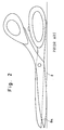
- Figure 1 shows common scissors according to prior art.
- the lower blade 1 extends proximally - towards the user - to form the upper handle 3.
- the upper blade 2 extends proximally to form the lower handle 4.
- the two blades/handles cross at the pivot 5 so as to be free to move past one another.
- the sharp edges 6 and 7 of the blades 1 and 2 cut the material as the handles 3 and 4 are pushed together. Comparing the height of the cutting point 8 above the table surface 9 on Figure 1 where the scissors are opened, to the height of the point 8a on Figure 2 where the scissors are closed, it becomes clear that the material being cut has to be repeatedly lifted off the table surface 9. Shaping the handles of tailoring scissors in special, ergonomic ways does not improve on this problem.
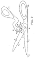
- Fig. 3 shows a preferred embodiment of the invention with a four-bar-linkage arranged so as to provide the desired kinematics for the scissors.
- the lower blade 11 of the scissors is one piece with the lower handle 13.
- the upper blade 12 is driven by the upper handle 14.
- the blades 11 and 12 are connected at the pivot location 15.
- Distal part 20 of the upper handle 14 is connected to the upper blade 12 at the pivot location 21.
- a short link 24 connects to the upper handle distal part 20 via pivot 22 and to the lower handle/blade 13;11 via pivot 23.
- Pivots 15,21,22 and 23 with the four parts of the scissors 11;13, 12, 24 and 20;14 form the four-bar linkage which drives the upper blade 12 while the lower blade 11 remains flat on the table surface 19. This allows the cutting point 18 to remain low over the table surface 19 when blades 11 and 12 are open as shown on the Fig. 3, as well as when they are closed as shown on the Fig. 4 (cutting point indicated as 18a).
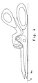
- Fig. 5 shows five positions of the scissors from fully open to fully closed.
- the center 27 of the upper handle 14 moves from the position 27A (over 27B,27C and 27D) to position 27E the tip 25 of the upper blade 12 moves from the position 25A (over 25B, 25C, and 25D) to 25E.
- the instantaneous center of rotation 26 between the upper handle 14 and the lower handle 13 is determined by the intersection of the lines connecting the pivots 21 to 15 and 22 to 23. It moves from the position 26A for the fully open scissors (over 26B, 26C and 26D) to the position 26E for the fully closed scissors.
Abstract
Description
- This invention relates to a kinematic improvement in the function of common scissors. The common scissors have two cutting blades which extend proximally to form the two handles. These are movable past one another on a pivot placed centrally. The pivot holds the two blades/handles together. When the scissors are used over a large surface, e.g. when tailoring on a table, the required movement of the handles lifts the point of the cutting (where the blade edges slide past one another) up from the table, disturbing the position of the material being cut. This is particularly annoying with fine, soft fabrics. Making the handles bent upwards so as to lift them off the surface would allow the lower blade to remain flat on the table, but would result in poorly balanced and difficult to use scissors. The advantage of being able to somewhat push against the table would also be lost.
- When such simple scissors are used for example to remove bandages, care must be exercised not to hurt the patient. This requires unnatural movement of the hand. As the lower blade of the scissors is controlled by the thumb of the operator, and it must not change angulation, the finger(s) of the hand and the whole hand must be moved to angulate the upper blade of the scissors. This movement can of course be learned, but does not come naturally.
- The same is true of surgical scissors. Typically the lower blade is out of the sight of the surgeon and should not be angulated so as to point deeper into tissues. This requires the thumb to be stationary and the hand to move.
A pair of scissors solving some of the above problems are known from DE-C-867 867 211, with the features as listed in the preamble of the claim. - The invention as claimed is intended to provide further improvement to the state of the art as illustrated by DE-C-867 211. For that purpose a kinematic arrangement of the scissor components has been designed. Normally, the lower blade of the scissors is controlled by the finger(s) of the hand, while the upper blade is articulated by the thumb. To achieve the kinematic connection of the scissors components a four-bar linkage mechanism in provided.
- The advantages offered by the invention are mainly the improved ergonomics of the scissors and better control over the cutting action, particularly when tailoring fabrics, or cutting tissues in surgery.
- The various features of novelty which characterise the invention are pointed out with particularity in the claims annexed to and forming part of this disclosure. For the better understanding of the invention, its operating advantages and specific objects attained by its use, reference should be had to the accompanying drawings and descriptive matter in which are illustrated and described preferred embodiments of the invention.
- In the drawings:
- Fig. 1 is a side view of a prior art scissors in the open state;
- Fig. 2 is a side view of the prior art scissors according to Fig. 1 in the closed state;
- Fig. 3 is a side view of scissors according to the invention with a four-bar linkage in the open state;
- Fig. 4 is a side view of scissors according to Fig. 3 in the closed state; and
- Fig. 5 is a side view of scissors according to Fig. 3 showing several positions between fully open and fully closed.
- Figure 1 shows common scissors according to prior art. The lower blade 1 extends proximally - towards the user - to form the
upper handle 3. Theupper blade 2 extends proximally to form thelower handle 4. The two blades/handles cross at thepivot 5 so as to be free to move past one another. The sharp edges 6 and 7 of theblades 1 and 2 cut the material as thehandles table surface 9 on Figure 1 where the scissors are opened, to the height of the point 8a on Figure 2 where the scissors are closed, it becomes clear that the material being cut has to be repeatedly lifted off thetable surface 9. Shaping the handles of tailoring scissors in special, ergonomic ways does not improve on this problem. - Fig. 3 shows a preferred embodiment of the invention with a four-bar-linkage arranged so as to provide the desired kinematics for the scissors. The lower blade 11 of the scissors is one piece with the
lower handle 13. Theupper blade 12 is driven by theupper handle 14. Theblades 11 and 12 are connected at thepivot location 15.Distal part 20 of theupper handle 14 is connected to theupper blade 12 at thepivot location 21. Ashort link 24 connects to the upper handledistal part 20 viapivot 22 and to the lower handle/blade 13;11 viapivot 23.Pivots upper blade 12 while the lower blade 11 remains flat on thetable surface 19. This allows thecutting point 18 to remain low over thetable surface 19 whenblades 11 and 12 are open as shown on the Fig. 3, as well as when they are closed as shown on the Fig. 4 (cutting point indicated as 18a). - Fig. 5 shows five positions of the scissors from fully open to fully closed. As the center 27 of the
upper handle 14 moves from theposition 27A (over 27B,27C and 27D) to position 27E thetip 25 of theupper blade 12 moves from theposition 25A (over 25B, 25C, and 25D) to 25E. The instantaneous center of rotation 26 between theupper handle 14 and thelower handle 13 is determined by the intersection of the lines connecting thepivots 21 to 15 and 22 to 23. It moves from theposition 26A for the fully open scissors (over 26B, 26C and 26D) to theposition 26E for the fully closed scissors.
Claims (1)
- Scissors for household and medical use comprising an upper blade (12) and a lower blade (11) defining a distal region, an upper handle (14) and a lower handle (13) defining a proximal region, said lower blade (11) and lower handle (13) being one piece, and said upper blade (12) and upper handle (14) being two separate pieces; means pivotally connecting said upper blade (12) to said lower blade (11) at a first pivot location (15); means pivotally connecting said upper blade (12) to said upper handle (14) at a second pivot location (21); a link bar (24) pivotally connected to said upper handle (14) and to said lower handle (13) at third (22) and fourth pivot locations (23) respectively, thereby forming a four-bar linkage movably linking said upper blade (12) to said lower blade (11) such that said upper blade (12) is movable by said upper handle (14) while leaving said one-piece lower blade (11) and handle (13) stationary, and wherein a locus of instantaneous centres of rotation (26) is defined between said upper (14) and lower handles (13) as determined by intersections of lines passing respectively through the centres of said first (15) and second pivot location (21) and said third (22) and fourth pivot location (23)
characterized in that said locus of instantaneous centres of rotation lies in said distal region for all positions of said upper blade (12).
Applications Claiming Priority (2)
| Application Number | Priority Date | Filing Date | Title |
|---|---|---|---|
| US490346 | 1990-03-08 | ||
| US07/490,346 US5014433A (en) | 1990-03-08 | 1990-03-08 | Scissors for household and medical uses |
Publications (2)
| Publication Number | Publication Date |
|---|---|
| EP0445371A1 EP0445371A1 (en) | 1991-09-11 |
| EP0445371B1 true EP0445371B1 (en) | 1993-02-03 |
Family
ID=23947663
Family Applications (1)
| Application Number | Title | Priority Date | Filing Date |
|---|---|---|---|
| EP90122045A Expired - Lifetime EP0445371B1 (en) | 1990-03-08 | 1990-11-17 | Scissors for household and medical uses |
Country Status (9)
| Country | Link |
|---|---|
| US (1) | US5014433A (en) |
| EP (1) | EP0445371B1 (en) |
| JP (1) | JP2673842B2 (en) |
| KR (1) | KR0164854B1 (en) |
| AT (1) | ATE85260T1 (en) |
| DE (1) | DE69000875T2 (en) |
| DK (1) | DK0445371T3 (en) |
| ES (1) | ES2038031T3 (en) |
| GR (1) | GR3007618T3 (en) |
Families Citing this family (11)
| Publication number | Priority date | Publication date | Assignee | Title |
|---|---|---|---|---|
| DE69301979T2 (en) * | 1992-08-21 | 1996-09-19 | Ao Forschungsinst | Scissors and interchangeable, twisted blade inserts for scissors |
| AT404003B (en) * | 1996-07-19 | 1998-07-27 | Carp Gheorghe | SCISSORS OR PLIERS |
| US6685716B1 (en) * | 2000-01-04 | 2004-02-03 | Transvascular, Inc. | Over-the-wire apparatus and method for open surgery making of fluid connection between two neighboring vessels |
| US6752054B2 (en) | 2000-12-28 | 2004-06-22 | Irwin Industrial Tool Company | Utility cutting tool having toggle link mechanism field of the invention |
| KR20030071800A (en) * | 2001-02-07 | 2003-09-06 | 아키라 미카미 | Scissors |
| FR2837126B1 (en) * | 2002-03-18 | 2004-12-03 | Joseph Sampognaro | ARTICULATED SCISSORS FOR PIZZA CUTTING |
| JP2004209042A (en) | 2003-01-06 | 2004-07-29 | Olympus Corp | Ultrasonic treatment apparatus |
| DE102007053061A1 (en) | 2007-11-05 | 2009-05-07 | Zematec Antriebstechnik | Medical instrument such as scissors, has branch section with ring movably arranged at branch section for accommodating fingers, where ring and branch section are connected with each other by pin |
| DE202008014291U1 (en) | 2008-10-17 | 2009-01-22 | Hidde, Axel R., Dr. | Cutting hand tools |
| US9358693B1 (en) * | 2015-03-20 | 2016-06-07 | Eric T. Berger | Shears |
| USD992390S1 (en) * | 2021-01-22 | 2023-07-18 | Cygnus Medical Llc | Multipurpose shears |
Citations (1)
| Publication number | Priority date | Publication date | Assignee | Title |
|---|---|---|---|---|
| US2744323A (en) * | 1953-09-03 | 1956-05-08 | Kuhlman Stanley | Shears |
Family Cites Families (15)
| Publication number | Priority date | Publication date | Assignee | Title |
|---|---|---|---|---|
| US883457A (en) * | 1907-12-19 | 1908-03-31 | Charles Geis | Shears. |
| US942043A (en) * | 1909-07-16 | 1909-11-30 | Detroit Shear Company | Shears. |
| US1012289A (en) * | 1910-10-17 | 1911-12-19 | Internat Tool Company | Compound-lever shears. |
| US2084633A (en) * | 1933-04-15 | 1937-06-22 | Erickson Carl Arvid | Adjustable pliers |
| US2442424A (en) * | 1944-10-03 | 1948-06-01 | Francis L Mcgary | Center cut shear |
| US2528816A (en) * | 1948-04-21 | 1950-11-07 | Elizabeth M Boyer | Hedge shears |
| DE867211C (en) * | 1951-01-31 | 1953-02-16 | Gertrud Droszella | scissors |
| GB1162492A (en) * | 1966-02-24 | 1969-08-27 | Wilkinson Sword Ltd | Improvements in or relating to Cutting Tools. |
| US3572192A (en) * | 1968-05-10 | 1971-03-23 | Stanley M Juras | Squeeze type tools |
| BE791259A (en) * | 1971-11-10 | 1973-05-10 | Wilkinson Sword Ltd | IMPROVEMENTS RELATED TO HAND TOOLS |
| JPS518725A (en) * | 1974-07-12 | 1976-01-23 | Kumagai Gumi Co Ltd | KONKURIITOHOKYORINGUSOCHI |
| GB1522144A (en) * | 1975-10-24 | 1978-08-23 | Holdema Ltd | Crimping and/or cutting device |
| GB1541580A (en) * | 1977-10-20 | 1979-03-07 | Stebbings L A | Toggle action for hand tools |
| US4381661A (en) * | 1980-03-19 | 1983-05-03 | C. A. Weidmuller Gmbh & Co. | Tool having two working jaws |
| US4525929A (en) * | 1982-09-27 | 1985-07-02 | Brophy Sr H Joseph | Cutting device |
-
1990
- 1990-03-08 US US07/490,346 patent/US5014433A/en not_active Expired - Lifetime
- 1990-11-17 ES ES199090122045T patent/ES2038031T3/en not_active Expired - Lifetime
- 1990-11-17 AT AT90122045T patent/ATE85260T1/en not_active IP Right Cessation
- 1990-11-17 DK DK90122045.9T patent/DK0445371T3/en active
- 1990-11-17 EP EP90122045A patent/EP0445371B1/en not_active Expired - Lifetime
- 1990-11-17 DE DE9090122045T patent/DE69000875T2/en not_active Expired - Lifetime
-
1991
- 1991-02-28 KR KR1019910003244A patent/KR0164854B1/en not_active IP Right Cessation
- 1991-03-07 JP JP3065232A patent/JP2673842B2/en not_active Expired - Lifetime
-
1993
- 1993-04-12 GR GR930400504T patent/GR3007618T3/el unknown
Patent Citations (1)
| Publication number | Priority date | Publication date | Assignee | Title |
|---|---|---|---|---|
| US2744323A (en) * | 1953-09-03 | 1956-05-08 | Kuhlman Stanley | Shears |
Also Published As
| Publication number | Publication date |
|---|---|
| ATE85260T1 (en) | 1993-02-15 |
| ES2038031T3 (en) | 1993-07-01 |
| KR0164854B1 (en) | 1999-02-01 |
| DK0445371T3 (en) | 1993-06-07 |
| JP2673842B2 (en) | 1997-11-05 |
| KR920005698A (en) | 1992-04-03 |
| DE69000875T2 (en) | 1993-07-22 |
| GR3007618T3 (en) | 1993-08-31 |
| EP0445371A1 (en) | 1991-09-11 |
| JPH07241393A (en) | 1995-09-19 |
| US5014433A (en) | 1991-05-14 |
| DE69000875D1 (en) | 1993-03-18 |
Similar Documents
| Publication | Publication Date | Title |
|---|---|---|
| US4753235A (en) | Forceps-type surgical instrument | |
| EP0445371B1 (en) | Scissors for household and medical uses | |
| AU634765B2 (en) | Surgical scalpel with retractable blade guard | |
| US5282817A (en) | Actuating handle for multipurpose surgical instrument | |
| USRE36666E (en) | Micro-instrument | |
| DE60300196T2 (en) | Rotating articulated arm for a surgical tray | |
| US4034746A (en) | Retractor | |
| DE60309401T2 (en) | Medical device with expandable element | |
| US5893873A (en) | Surgical instrument having a handle with a removable, rotatable tip | |
| US6500188B2 (en) | Ultrasonic surgical instrument with finger actuator | |
| CA2103507C (en) | Locking mechanism for endoscopic or laparoscopic surgical instruments | |
| US6280459B1 (en) | Back biting surgical instrument | |
| US4751925A (en) | Gripper for surgical purposes | |
| US5475925A (en) | Three-piece retractable-bladed knife | |
| US6958038B2 (en) | Multipositional ratchet device for surgical retractor | |
| US3659343A (en) | Suture cutter | |
| US6944914B2 (en) | Handle and forceps/tweezers and method and apparatus for designing the like | |
| WO2002030303A1 (en) | Microsurgical instrument | |
| US10413290B1 (en) | Combined needle holder scissors | |
| GB2348390A (en) | Interchangable handles | |
| JPH10179602A (en) | Structure of treating part in treating implement for endoscope | |
| CN220089586U (en) | Chest mirror list Kong Shoushu cuts | |
| JPS6121052Y2 (en) | ||
| US20210298781A1 (en) | Surgical instrument | |
| EP1164949B1 (en) | Surgical cutting instrument |
Legal Events
| Date | Code | Title | Description |
|---|---|---|---|
| PUAI | Public reference made under article 153(3) epc to a published international application that has entered the european phase |
Free format text: ORIGINAL CODE: 0009012 |
|
| 17P | Request for examination filed |
Effective date: 19901117 |
|
| AK | Designated contracting states |
Kind code of ref document: A1 Designated state(s): AT BE CH DE DK ES FR GB GR IT LI LU NL SE |
|
| 18W | Application withdrawn |
Withdrawal date: 19911111 |
|
| D18W | Application withdrawn (deleted) | ||
| 17Q | First examination report despatched |
Effective date: 19911218 |
|
| GRAA | (expected) grant |
Free format text: ORIGINAL CODE: 0009210 |
|
| AK | Designated contracting states |
Kind code of ref document: B1 Designated state(s): AT BE CH DE DK ES FR GB GR IT LI LU NL SE |
|
| REF | Corresponds to: |
Ref document number: 85260 Country of ref document: AT Date of ref document: 19930215 Kind code of ref document: T |
|
| REF | Corresponds to: |
Ref document number: 69000875 Country of ref document: DE Date of ref document: 19930318 |
|
| RAP2 | Party data changed (patent owner data changed or rights of a patent transferred) |
Owner name: AO-FORSCHUNGSINSTITUT DAVOS |
|
| ET | Fr: translation filed | ||
| ITF | It: translation for a ep patent filed |
Owner name: STUDIO ING. ALFREDO RAIMONDI |
|
| REG | Reference to a national code |
Ref country code: DK Ref legal event code: T3 |
|
| REG | Reference to a national code |
Ref country code: ES Ref legal event code: FG2A Ref document number: 2038031 Country of ref document: ES Kind code of ref document: T3 |
|
| REG | Reference to a national code |
Ref country code: GR Ref legal event code: FG4A Free format text: 3007618 |
|
| PG25 | Lapsed in a contracting state [announced via postgrant information from national office to epo] |
Ref country code: LU Free format text: LAPSE BECAUSE OF NON-PAYMENT OF DUE FEES Effective date: 19931130 |
|
| PLBE | No opposition filed within time limit |
Free format text: ORIGINAL CODE: 0009261 |
|
| STAA | Information on the status of an ep patent application or granted ep patent |
Free format text: STATUS: NO OPPOSITION FILED WITHIN TIME LIMIT |
|
| EPTA | Lu: last paid annual fee | ||
| 26N | No opposition filed | ||
| EAL | Se: european patent in force in sweden |
Ref document number: 90122045.9 |
|
| REG | Reference to a national code |
Ref country code: GB Ref legal event code: IF02 |
|
| PGFP | Annual fee paid to national office [announced via postgrant information from national office to epo] |
Ref country code: NL Payment date: 20041019 Year of fee payment: 15 |
|
| PGFP | Annual fee paid to national office [announced via postgrant information from national office to epo] |
Ref country code: AT Payment date: 20041020 Year of fee payment: 15 |
|
| PGFP | Annual fee paid to national office [announced via postgrant information from national office to epo] |
Ref country code: SE Payment date: 20041109 Year of fee payment: 15 |
|
| PGFP | Annual fee paid to national office [announced via postgrant information from national office to epo] |
Ref country code: DK Payment date: 20041110 Year of fee payment: 15 |
|
| PGFP | Annual fee paid to national office [announced via postgrant information from national office to epo] |
Ref country code: LU Payment date: 20041111 Year of fee payment: 15 |
|
| PGFP | Annual fee paid to national office [announced via postgrant information from national office to epo] |
Ref country code: ES Payment date: 20041117 Year of fee payment: 15 |
|
| PGFP | Annual fee paid to national office [announced via postgrant information from national office to epo] |
Ref country code: GR Payment date: 20041130 Year of fee payment: 15 |
|
| PGFP | Annual fee paid to national office [announced via postgrant information from national office to epo] |
Ref country code: BE Payment date: 20041201 Year of fee payment: 15 |
|
| PG25 | Lapsed in a contracting state [announced via postgrant information from national office to epo] |
Ref country code: IT Free format text: LAPSE BECAUSE OF NON-PAYMENT OF DUE FEES Effective date: 20051117 Ref country code: AT Free format text: LAPSE BECAUSE OF NON-PAYMENT OF DUE FEES Effective date: 20051117 |
|
| PG25 | Lapsed in a contracting state [announced via postgrant information from national office to epo] |
Ref country code: SE Free format text: LAPSE BECAUSE OF NON-PAYMENT OF DUE FEES Effective date: 20051118 Ref country code: ES Free format text: LAPSE BECAUSE OF NON-PAYMENT OF DUE FEES Effective date: 20051118 |
|
| PG25 | Lapsed in a contracting state [announced via postgrant information from national office to epo] |
Ref country code: BE Free format text: LAPSE BECAUSE OF NON-PAYMENT OF DUE FEES Effective date: 20051130 Ref country code: DK Free format text: LAPSE BECAUSE OF NON-PAYMENT OF DUE FEES Effective date: 20051130 |
|
| PG25 | Lapsed in a contracting state [announced via postgrant information from national office to epo] |
Ref country code: NL Free format text: LAPSE BECAUSE OF NON-PAYMENT OF DUE FEES Effective date: 20060601 |
|
| REG | Reference to a national code |
Ref country code: DK Ref legal event code: EBP |
|
| EUG | Se: european patent has lapsed | ||
| NLV4 | Nl: lapsed or anulled due to non-payment of the annual fee |
Effective date: 20060601 |
|
| REG | Reference to a national code |
Ref country code: ES Ref legal event code: FD2A Effective date: 20051118 |
|
| BERE | Be: lapsed |
Owner name: *AO-FORSCHUNGSINSTITUT DAVOS Effective date: 20051130 |
|
| PG25 | Lapsed in a contracting state [announced via postgrant information from national office to epo] |
Ref country code: GR Free format text: LAPSE BECAUSE OF NON-PAYMENT OF DUE FEES Effective date: 19930203 |
|
| PGFP | Annual fee paid to national office [announced via postgrant information from national office to epo] |
Ref country code: DE Payment date: 20091126 Year of fee payment: 20 Ref country code: CH Payment date: 20091120 Year of fee payment: 20 |
|
| PGFP | Annual fee paid to national office [announced via postgrant information from national office to epo] |
Ref country code: FR Payment date: 20091209 Year of fee payment: 20 Ref country code: GB Payment date: 20091130 Year of fee payment: 20 |
|
| REG | Reference to a national code |
Ref country code: CH Ref legal event code: PL |
|
| REG | Reference to a national code |
Ref country code: GB Ref legal event code: PE20 Expiry date: 20101116 |
|
| PG25 | Lapsed in a contracting state [announced via postgrant information from national office to epo] |
Ref country code: GB Free format text: LAPSE BECAUSE OF EXPIRATION OF PROTECTION Effective date: 20101116 |
|
| PG25 | Lapsed in a contracting state [announced via postgrant information from national office to epo] |
Ref country code: DE Free format text: LAPSE BECAUSE OF EXPIRATION OF PROTECTION Effective date: 20101117 |