EP0445176B1 - Device for supporting artificial teeth in a jaw and method for making same - Google Patents
Device for supporting artificial teeth in a jaw and method for making same Download PDFInfo
- Publication number
- EP0445176B1 EP0445176B1 EP89913077A EP89913077A EP0445176B1 EP 0445176 B1 EP0445176 B1 EP 0445176B1 EP 89913077 A EP89913077 A EP 89913077A EP 89913077 A EP89913077 A EP 89913077A EP 0445176 B1 EP0445176 B1 EP 0445176B1
- Authority
- EP
- European Patent Office
- Prior art keywords
- extension members
- tooth
- secured
- supporting means
- bridge
- Prior art date
- Legal status (The legal status is an assumption and is not a legal conclusion. Google has not performed a legal analysis and makes no representation as to the accuracy of the status listed.)
- Expired - Lifetime
Links
Images

Classifications
-
- A—HUMAN NECESSITIES
- A61—MEDICAL OR VETERINARY SCIENCE; HYGIENE
- A61C—DENTISTRY; APPARATUS OR METHODS FOR ORAL OR DENTAL HYGIENE
- A61C8/00—Means to be fixed to the jaw-bone for consolidating natural teeth or for fixing dental prostheses thereon; Dental implants; Implanting tools
- A61C8/0048—Connecting the upper structure to the implant, e.g. bridging bars
Definitions
- the present invention relates to a device for supporting artificial teeth, which is intended to be secured to anchoring elements embedded entirely or partially in a jaw.
- the invention also relates to a method for making the device.
- the first step to be taken, after examination and thorough diagnosis, is to insert anchoring bodies, sometimes referred to as fixtures, in the jaw bone by surgical operation, in the area of the jaw where the denture is to be fixed.
- the anchoring body may consist e.g of a screw of titanium, having an external and an internal thread.
- each anchoring body is then fixed a spacer member of titanium by means of a screw which is screwed in the internal thread of the anchoring body.
- the spacer member extends through the mucous membrane in the jaw and is axially aligned with the anchoring body.
- One spacer member and one anchoring body together form an anchoring element to which a denture can be permanently secured.
- a model is prepared of the jaw, as it appears with the implanted anchoring bodies and the spacer members fixed thereto.
- impression elements are screwed to the spacer members, and an impression is made of the jaw in this state.
- the impression elements are removed from the spacer members, whereupon the entire plaster impression can be removed from the jaw.
- Model spacer members and model anchoring bodies of brass are then screwed into the impression elements so as to have the same inclination and vertical position as the real anchoring bodies and spacer members in the jaw, and the impression is filled with plaster.
- plaster has hardened and the impression with the impression elements has finally been loosened from the plaster with the brass anchoring bodies and brass spacer members, an exact model of the jaw has been obtained.
- a plaster model of the other jaw is also prepared.
- the patient will have to bite in a soft mass, thus providing a bite impression showing how the patient's jaws are located in relation to each other and thus what space is available for building up an artificial row of teeth.
- the plaster models of the patient's jaws are fixed in an artificial jaw-joint which, on the basis of the bite impression, is adjusted so as to agree with the patient's bite.
- the wax ridge serves as a model for the bridge which is to be cast in the next step and which eventually should support the artificial teeth. It is therefore moulded after the jaw and provided with holes registering with the spacer members to make it possible to subsequently screw the finished bridge to the spacer members.
- the wax model When the wax model is finished, it is enclosed in a mould, whereupon the wax is evaportated and gold is slung into the mould.
- the gold bridge When the gold solidifies, it however undergoes dimensional changes, which sometimes means that the gold bridge thus cast will not fit exactly on the spacer members, which in turn means that the spacer members and anchoring bodies would be subjected to undesired stresses if the bridge were mounted in this state.
- the gold bridge must be modified, which is done by sawing it off at one or more points, adjusted to the spacer members and finally soldered together.
- the gold bridge When the gold bridge is finished, it is provided with gingive-like plastic and artificial teeth, holes being left in the extension of the holes in the bridge.
- the denture is thereafter ready for mounting in the patient's mouth by means of screws which are passed through the holes in the plastic and the bridge and screwed in the internal thread in the head of the screw holding the spacer member and the anchoring body together. Finally, the holes in the plastic are filled with plastic and ground smooth.
- a first problem is that it demands considerable efforts and is time-consuming.
- a second problem is that the gold in the bridge and the titanium in the spacer members may together give rise to undesired electrochemical reactions in the mouth.
- a third problem is linked with the above-mentioned resorption in the jaw. If there have not been any teeth in the jaw for a long time, it may be heavily resorbed. This in turn means that the distance between the toothless jaw and the opposite jaw is considerable and that a substantial build-up of the toothless jaw is required for placing the aritificial teeth on a correct height for a proper bite. In other words, the gold bridge must have sufficient strength and a considerable extent in the vertical direction, which makes it heavy. This may cause discomfort to the patient.
- a fourth problem which is related to the material used in the bridge and the weight thereof is the cost aspect. Since gold is an expensive material and there is required as much as between 15 and 40 g for a regular bridge, it will be expensive to make.
- a fifth problem is the above-mentioned dimensional change in connection with casting, making it difficult to produce a bridge which, when secured to the anchoring bodies and the spacer members, does not give rise to stresses between the different anchoring bodies.
- a sixth problem is that, when trying out the spacer members, the mucous membrane is often swollen because of the surgical operation for exposing the anchoring bodies and the an ⁇ sthetic administered in this connection, which may result in that too long spacer members are mounted in the anchoring bodies. When the swelling in the mucous membrane disappears, the spacer members will project to an excessive extent above the mucous membrane, which is less desirable from the ⁇ sthetic point of view.
- the bridge which, as in the case related above, is anchored in the jaw by means of anchoring bodies and spacer members.
- the bridge is made up of a number of bridge elements, each of which consists of a mounting member screwed in a spacer member, and two wings projecting on each side of the mounting member towards the wing on the bridge element of the adjacent spacer member.
- the bridge elements When building up the bridge, the bridge elements are fitted to each other, and connecting surfaces are prepared between the bridge elements.
- the bridge is welded together at the connecting surfaces and provided with plastic and teeth in customary manner.
- the bridge of this design is made of titanium, which eleminates the problems of undesired electrochemical reactions and also reduces the weight and the price of the bridge.
- the bridge described in SE-B-455 156 however suffers from other drawbacks as well. Since the spacer members, as described above, are inclined and located on different vertical levels in relation to each other, it is a complicated matter to adjust the bridge elements to each other in a manner to obtain accurate connecting surfaces. Further, if the jaw is slightly resorbed, it is difficult to achieve a suitable bite level since the bridge elements are not vertically adjustable in the same manner as the known gold bridge mentioned above, but may require too much space. If the jaw is heavily resorbed, it may be necessary to place the row of teeth at a considerable distance in the sagittal direction in front of the bridge proper. In such a case, there may be a problem of insufficient strenght since the teeth are not supported by the bridge.
- the object of the present invention thus is to provide a device for supporting artificial teeth in a jaw and a method for making the device, in order to solve the above-mentioned problems inherent in the prior art technique.
- extension members and a tooth-supporting means are cut such that the end surface of each extension member is located in the same plane as the corresponding engagement surface of the tooth-supporting means in the finished device.
- the height above the anchoring elements of a bridge and, hence, of the artificial teeth fixed thereon can easily be adjusted according to the patient's needs, so as to provide a suitable bite level, whether the bone in the jaw is slightly or heavily resorbed.
- the end surfaces of the extension members also form a seat on which the tooth-supporting means, which may consist of a prefabricated beam obtained by casting, milling or sawing, can easily be secured.
- the device Since the extent of the bridge in the sagittal direction can be adjusted according to the patient's needs, the row of artificial teeth will also be constantly supported by the bridge from the side of the anchoring bodies, thus providing sufficient strength. Since the device consists of a tooth-supporting means and extension members which are welded in an accurately defined position to the tooth-supporting means, the device can be secured to the anchoring bodies or the spacer members without any stresses arising therebetween. By means of the extension members it is also possible to solve the problem of excessively long spacer members, whereby to provide an ⁇ sthetically pleasing denture.
- a tube 19 is thereafter fixed in each spacer member 4 on the model of the toothless jaw.
- This tube is cylindrical and has an end shaped to fit on the spacer member 4.
- the tube 19 is secured to the spacer member 4 by a screw 23 which is passed through the tube and screwed in the internal thread in the head 6 of the screw 5, such that the screw 23 enters into engagement with the abutment 21 in the tube.
- the longitudinal axis of the tube 19 will thus be aligned with the longitudinal axis of the spacer member 4 and the anchoring body 1.
- the model with the tubes 19 screwed to it is thereafter fixed in the artificial jaw-joint, and a plane through the tubes giving the patient a correct bite level is determined and marked.
- Fig. 3 shows the model of the jaw with spacer members 4 and tubes 19 mounted thereon. It appears from this Figure that the spacer members 4 are slightly inclined in relation to each other and also are located on different vertical levels, which in turn means that the tubes will be inclined in relation to each other and that their free end surfaces will be on different vertical levels.
- the plane 30 in which the tubes 19 should be cut is indicated by a dashed line in the Figure.
- the model with the tubes is then moved to a spark erosion machine of the wire electrode type, in which the tubes are cut to the indicated height, such that the free end surface of each tube will be located in the indicated plane 30.
- the suitable shape of a bridge to support the artificial teeth is then determined as well as a suitable position therefor in the sagittal direction. This can be done, for instance by using a mouldable material and making a model of the bridge on the model jaw in the artificial jaw-joint.
- the bridge is cut e.g. from a titanium sheet.
- the bridge can also be made from a prefabricated beam obtained by casting, milling or sawing. According to a further variant, the bridge can be cast by the model.
- the bridge is cut in a plane by wire electrode spark erosion, such that the surfaces of the bridge engaging the end surfaces of the tubes will be in a common plane.
- the areas of the bridge between the engagement surfaces can thereafter be shaped as desired.
- Fig. 4 schematically shows a possible appearance from above of a bridge 25 when mounted on the tubes 19.
- the bridge has been cut from a metal sheet and has an arcuate portion 27 which conforms to the shape of the jaw and above which the artificial teeth should be placed. From the arcuate portion, tongues 29 extend which are fixed to the tubes 19.
- Fig. 5 shows another example of a bridge 25.
- the bridge consists of a narrow beam provided straight above the tubes 19.
- the beam When the beam has been correctly positioned on the tubes, it is fixed thereto, for instance by laser welding.
- the plaster in the model is thereafter removed, such that the model anchoring bodies and the model spacer members can be exposed and unscrewed from the tubes.
- the beam and the tubes are placed in a jig, and holes are made through the beam in the extensions of the tubes.
- the holes may be provided e.g. by drilling.
- the beam is thereafter provided in known manner with plastic or porcelain or composite material, as well as artificial teeth, and is to the patient's jaw, whereupon the screw holes in the plastic are filled.
- anchoring bodies are inserted by surgical operation in the patient's jaw, and a model 60 of the jaw with anchoring bodies and spacer members 4 mounted therein is prepared.
- Tubes 19 are thereafter fixed in the spacer members 4 in the model 60, as shown in Fig. 6, and a plane 64-66 is determined for each tube, giving a suitable length to the tube and, thus, a suitable position for a tooth-supporting bridge with respect to the location of the anchoring bodies.
- the planes are then elected so as to be located as close to the spacer members as possible.
- the planes 64-66 may, but need not necessarily be mutually parallel or be located in one and the same plane. If the planes are not parallel, they should preferably be at right angles to the longitudinal axes of the anchoring bodies.
- the model 60 with the tubes 19 is fixed in a suitable cutting machine, and the tubes 19 are cut in said planes 64-66.
- Cutting can be effected, e.g. by wire electrode spark erosion, laser cutting or sawing.
- a wax model of a bridge 61 having a laterally extending portion 62 and legs 63 (see Fig. 7) projecting there-from.
- a bridge 61 of titanium is cast.
- the surfaces of the bridge intended to engage the tubes 19 are then processed so as to fit exactly on the tubes 19 in the planes 64-66. Such processing may consist in removing burrs and other casting defects or of a cutting operation similar to that performed on the tubes.
- the cast bridge 61 with the legs 63 is welded onto the cut tubes 19, such that the bridge 61 and the tubes 19 form a device which fits exactly on the spacer members in the patient's jaw and which can thus be fixed thereon without any stresses arising between the anchoring bodies.
- the method and devices described above can be modified in many different ways within the scope of the accompanying claims.
- the material used for the bridge and the tubes preferably is titanium, but also other materials are conceivable.
- the tubes can be shortened in many different ways.
- the wire electrode spark erosion technique stated above may be replaced by surface grinding or laser cutting.
- the bridge can be fixed to the tubes in many different ways, for instance by gluing, screwing or soldering.
- the device according to the invention may of course also be fixed to anchoring bodies and spacer members of a design different from that now described and shown.
- the shape and the cross-section of the tubes may also be modified.
Landscapes
- Health & Medical Sciences (AREA)
- Public Health (AREA)
- Dentistry (AREA)
- Epidemiology (AREA)
- Life Sciences & Earth Sciences (AREA)
- Animal Behavior & Ethology (AREA)
- Orthopedic Medicine & Surgery (AREA)
- Veterinary Medicine (AREA)
- General Health & Medical Sciences (AREA)
- Oral & Maxillofacial Surgery (AREA)
- Prostheses (AREA)
- Dental Prosthetics (AREA)
- Testing Of Coins (AREA)
- Cable Accessories (AREA)
- Load-Engaging Elements For Cranes (AREA)
- Control Of Vending Devices And Auxiliary Devices For Vending Devices (AREA)
- Saccharide Compounds (AREA)
- Dowels (AREA)
- Paper (AREA)
- Nitrogen Condensed Heterocyclic Rings (AREA)
- Executing Machine-Instructions (AREA)
- Butt Welding And Welding Of Specific Article (AREA)
Abstract
Description
- The present invention relates to a device for supporting artificial teeth, which is intended to be secured to anchoring elements embedded entirely or partially in a jaw.
- The invention also relates to a method for making the device.
- It happens quite often, as a consequence of a disease or an accident, that people lose several teeth in one or both jaws. These teeth must be replaced by artificial ones, which may be done, for instance with the aid of a detachable denture, fixed bridges or, as in the case of the present invention, a denture permanently anchored in the jaw bone.
- Different methods and devices are currently used for anchoring a denture in the jaw bone. A method and a device generally used in Swedish dentistry will be described hereinbelow.
- The first step to be taken, after examination and thorough diagnosis, is to insert anchoring bodies, sometimes referred to as fixtures, in the jaw bone by surgical operation, in the area of the jaw where the denture is to be fixed. The anchoring body may consist e.g of a screw of titanium, having an external and an internal thread.
- When the anchoring bodies after healing are fixed in the jaw, the surgeon loosens the flap of the mucous membrane covering the anchoring bodies during the healing process so as to expose the anchoring bodies. In each anchoring body is then fixed a spacer member of titanium by means of a screw which is screwed in the internal thread of the anchoring body. The spacer member extends through the mucous membrane in the jaw and is axially aligned with the anchoring body. One spacer member and one anchoring body together form an anchoring element to which a denture can be permanently secured.
- In a jaw without any teeth, parts of the bone will gradually be resorbed. Thus, the number of sites where anchoring bodies can be implanted will be limited. This, togehter with the fact that there is no easy way for controlling the orientation and the depth of the anchoring bodies when implanting them in the jaw bone, entails that the anchoring bodies, and thus the spacer members, may be inclined in relation to each other and that the spacer members may protrude over the mucous membrane to a varying degree.
- After the spacer members have been mounted on the anchoring bodies, a model is prepared of the jaw, as it appears with the implanted anchoring bodies and the spacer members fixed thereto. To this end, impression elements are screwed to the spacer members, and an impression is made of the jaw in this state. When the impression has set, the impression elements are removed from the spacer members, whereupon the entire plaster impression can be removed from the jaw. Model spacer members and model anchoring bodies of brass are then screwed into the impression elements so as to have the same inclination and vertical position as the real anchoring bodies and spacer members in the jaw, and the impression is filled with plaster. When the plaster has hardened and the impression with the impression elements has finally been loosened from the plaster with the brass anchoring bodies and brass spacer members, an exact model of the jaw has been obtained.
- In this connection, a plaster model of the other jaw is also prepared. Finally, the patient will have to bite in a soft mass, thus providing a bite impression showing how the patient's jaws are located in relation to each other and thus what space is available for building up an artificial row of teeth.
- The plaster models of the patient's jaws are fixed in an artificial jaw-joint which, on the basis of the bite impression, is adjusted so as to agree with the patient's bite.
- To the model of the toothless jaw is then applied a wax ridge in which artificial teeth are placed in a manner to provide a correct bite and an æsthetic appearance. As a final check, the wax ridge with the teeth inserted therein is tried in the patient's mouth.
- The wax ridge serves as a model for the bridge which is to be cast in the next step and which eventually should support the artificial teeth. It is therefore moulded after the jaw and provided with holes registering with the spacer members to make it possible to subsequently screw the finished bridge to the spacer members.
- When the wax model is finished, it is enclosed in a mould, whereupon the wax is evaportated and gold is slung into the mould.
- When the gold solidifies, it however undergoes dimensional changes, which sometimes means that the gold bridge thus cast will not fit exactly on the spacer members, which in turn means that the spacer members and anchoring bodies would be subjected to undesired stresses if the bridge were mounted in this state. Thus, the gold bridge must be modified, which is done by sawing it off at one or more points, adjusted to the spacer members and finally soldered together.
- When the gold bridge is finished, it is provided with gingive-like plastic and artificial teeth, holes being left in the extension of the holes in the bridge. The denture is thereafter ready for mounting in the patient's mouth by means of screws which are passed through the holes in the plastic and the bridge and screwed in the internal thread in the head of the screw holding the spacer member and the anchoring body together. Finally, the holes in the plastic are filled with plastic and ground smooth.
- As mentioned above, this method of preparing, trying out and fixing a denture in the patient's jaw is generally used in Sweden today. This technique however entails different problems.
- A first problem is that it demands considerable efforts and is time-consuming.
- A second problem is that the gold in the bridge and the titanium in the spacer members may together give rise to undesired electrochemical reactions in the mouth.
- A third problem is linked with the above-mentioned resorption in the jaw. If there have not been any teeth in the jaw for a long time, it may be heavily resorbed. This in turn means that the distance between the toothless jaw and the opposite jaw is considerable and that a substantial build-up of the toothless jaw is required for placing the aritificial teeth on a correct height for a proper bite. In other words, the gold bridge must have sufficient strength and a considerable extent in the vertical direction, which makes it heavy. This may cause discomfort to the patient.
- A fourth problem which is related to the material used in the bridge and the weight thereof is the cost aspect. Since gold is an expensive material and there is required as much as between 15 and 40 g for a regular bridge, it will be expensive to make.
- A fifth problem is the above-mentioned dimensional change in connection with casting, making it difficult to produce a bridge which, when secured to the anchoring bodies and the spacer members, does not give rise to stresses between the different anchoring bodies.
- A sixth problem is that, when trying out the spacer members, the mucous membrane is often swollen because of the surgical operation for exposing the anchoring bodies and the anæsthetic administered in this connection, which may result in that too long spacer members are mounted in the anchoring bodies. When the swelling in the mucous membrane disappears, the spacer members will project to an excessive extent above the mucous membrane, which is less desirable from the æsthetic point of view.
- The above-mentioned problems are well known to those skilled in the art, and many attempts have been made to solve them.
- One proposal for a solution is described SE-B-455 156. This document describes a bridge which, as in the case related above, is anchored in the jaw by means of anchoring bodies and spacer members. In this case, the bridge is made up of a number of bridge elements, each of which consists of a mounting member screwed in a spacer member, and two wings projecting on each side of the mounting member towards the wing on the bridge element of the adjacent spacer member. When building up the bridge, the bridge elements are fitted to each other, and connecting surfaces are prepared between the bridge elements. When all bridge elements have been adjusted to each other, the bridge is welded together at the connecting surfaces and provided with plastic and teeth in customary manner.
- The bridge of this design is made of titanium, which eleminates the problems of undesired electrochemical reactions and also reduces the weight and the price of the bridge.
- The bridge described in SE-B-455 156 however suffers from other drawbacks as well. Since the spacer members, as described above, are inclined and located on different vertical levels in relation to each other, it is a complicated matter to adjust the bridge elements to each other in a manner to obtain accurate connecting surfaces. Further, if the jaw is slightly resorbed, it is difficult to achieve a suitable bite level since the bridge elements are not vertically adjustable in the same manner as the known gold bridge mentioned above, but may require too much space. If the jaw is heavily resorbed, it may be necessary to place the row of teeth at a considerable distance in the sagittal direction in front of the bridge proper. In such a case, there may be a problem of insufficient strenght since the teeth are not supported by the bridge.
- The object of the present invention thus is to provide a device for supporting artificial teeth in a jaw and a method for making the device, in order to solve the above-mentioned problems inherent in the prior art technique.
- This object is achieved by means of a device and a method having the features stated in the claims.
- According to the invention, extension members and a tooth-supporting means are cut such that the end surface of each extension member is located in the same plane as the corresponding engagement surface of the tooth-supporting means in the finished device. By means of the extension members the height above the anchoring elements of a bridge and, hence, of the artificial teeth fixed thereon can easily be adjusted according to the patient's needs, so as to provide a suitable bite level, whether the bone in the jaw is slightly or heavily resorbed. The end surfaces of the extension members also form a seat on which the tooth-supporting means, which may consist of a prefabricated beam obtained by casting, milling or sawing, can easily be secured. Since the extent of the bridge in the sagittal direction can be adjusted according to the patient's needs, the row of artificial teeth will also be constantly supported by the bridge from the side of the anchoring bodies, thus providing sufficient strength. Since the device consists of a tooth-supporting means and extension members which are welded in an accurately defined position to the tooth-supporting means, the device can be secured to the anchoring bodies or the spacer members without any stresses arising therebetween. By means of the extension members it is also possible to solve the problem of excessively long spacer members, whereby to provide an æsthetically pleasing denture.
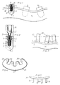
- Embodiments of the present invention will be described hereinafter with reference to the accompanying drawings, in which
- Fig. 1
- schematically shows a plurality of anchoring bodies implanted in the jaw, and spacer members secured to the anchoring bodies, one anchoring body and one spacer member being shown in cross-section;
- Fig. 2
- is a cross-section schematically showing a tube according to the invention when mounted on a spacer member, in turn mounted on an anchoring body;
- Fig. 3
- is a schematic side view showing a jaw with spacer members and tubes mounted therein;
- Fig. 4
- is a top plan view schematically showing one example of a bridge mounted on tubes;
- Fig. 5
- is a side view showing another example of a bridge mounted on tubes;
- Fig. 6
- is a schematic side view showing a model with tubes mounted thereon according to another embodiment of the invention; and
- Fig. 7
- is a schematic side view showing the same model as in Fig. 6 with a cast beam mounted thereon;
- When the spacer members have been secured to the anchoring bodies, a model of each jaw is made and a bite impression is taken, as described above.
- As shown in Fig. 2, a
tube 19 is thereafter fixed in eachspacer member 4 on the model of the toothless jaw. This tube is cylindrical and has an end shaped to fit on thespacer member 4. Thetube 19, preferably turned and made of titanium, further has an internal,annular abutment 21 at its end facing the spacer member. Thetube 19 is secured to thespacer member 4 by ascrew 23 which is passed through the tube and screwed in the internal thread in thehead 6 of thescrew 5, such that thescrew 23 enters into engagement with theabutment 21 in the tube. The longitudinal axis of thetube 19 will thus be aligned with the longitudinal axis of thespacer member 4 and the anchoringbody 1. - The model with the
tubes 19 screwed to it is thereafter fixed in the artificial jaw-joint, and a plane through the tubes giving the patient a correct bite level is determined and marked. - Fig. 3 shows the model of the jaw with
spacer members 4 andtubes 19 mounted thereon. It appears from this Figure that thespacer members 4 are slightly inclined in relation to each other and also are located on different vertical levels, which in turn means that the tubes will be inclined in relation to each other and that their free end surfaces will be on different vertical levels. Theplane 30 in which thetubes 19 should be cut is indicated by a dashed line in the Figure. - The model with the tubes is then moved to a spark erosion machine of the wire electrode type, in which the tubes are cut to the indicated height, such that the free end surface of each tube will be located in the indicated
plane 30. - In the artificial jaw-joint, the suitable shape of a bridge to support the artificial teeth is then determined as well as a suitable position therefor in the sagittal direction. This can be done, for instance by using a mouldable material and making a model of the bridge on the model jaw in the artificial jaw-joint.
- When this model is finished, the bridge is cut e.g. from a titanium sheet. The bridge can also be made from a prefabricated beam obtained by casting, milling or sawing. According to a further variant, the bridge can be cast by the model.
- In the same manner as in the case of the
tubes 19, the bridge is cut in a plane by wire electrode spark erosion, such that the surfaces of the bridge engaging the end surfaces of the tubes will be in a common plane. The areas of the bridge between the engagement surfaces can thereafter be shaped as desired. - Fig. 4 schematically shows a possible appearance from above of a
bridge 25 when mounted on thetubes 19. The bridge has been cut from a metal sheet and has anarcuate portion 27 which conforms to the shape of the jaw and above which the artificial teeth should be placed. From the arcuate portion,tongues 29 extend which are fixed to thetubes 19. - Fig. 5 shows another example of a
bridge 25. In this case, the bridge consists of a narrow beam provided straight above thetubes 19. - When the beam has been correctly positioned on the tubes, it is fixed thereto, for instance by laser welding.
- The plaster in the model is thereafter removed, such that the model anchoring bodies and the model spacer members can be exposed and unscrewed from the tubes. The beam and the tubes are placed in a jig, and holes are made through the beam in the extensions of the tubes. The holes may be provided e.g. by drilling. The beam is thereafter provided in known manner with plastic or porcelain or composite material, as well as artificial teeth, and is to the patient's jaw, whereupon the screw holes in the plastic are filled.
- Another currently preferred embodiment of the invention will now be described with reference to Figs. 6-8.
- In the same manner as in the prior art, anchoring bodies are inserted by surgical operation in the patient's jaw, and a
model 60 of the jaw with anchoring bodies andspacer members 4 mounted therein is prepared. -
Tubes 19 are thereafter fixed in thespacer members 4 in themodel 60, as shown in Fig. 6, and a plane 64-66 is determined for each tube, giving a suitable length to the tube and, thus, a suitable position for a tooth-supporting bridge with respect to the location of the anchoring bodies. The planes are then elected so as to be located as close to the spacer members as possible. The planes 64-66 may, but need not necessarily be mutually parallel or be located in one and the same plane. If the planes are not parallel, they should preferably be at right angles to the longitudinal axes of the anchoring bodies. - When the planes have been determined, the
model 60 with thetubes 19 is fixed in a suitable cutting machine, and thetubes 19 are cut in said planes 64-66. Cutting can be effected, e.g. by wire electrode spark erosion, laser cutting or sawing. - On the
cut tubes 19 on themodel 60 is thereafter made a wax model of abridge 61 having a laterally extendingportion 62 and legs 63 (see Fig. 7) projecting there-from. On the basis of this wax model, abridge 61 of titanium is cast. The surfaces of the bridge intended to engage thetubes 19 are then processed so as to fit exactly on thetubes 19 in the planes 64-66. Such processing may consist in removing burrs and other casting defects or of a cutting operation similar to that performed on the tubes. - Finally, the
cast bridge 61 with thelegs 63 is welded onto thecut tubes 19, such that thebridge 61 and thetubes 19 form a device which fits exactly on the spacer members in the patient's jaw and which can thus be fixed thereon without any stresses arising between the anchoring bodies. - If, on the other hand, a bridge had been moulded and cast directly on the spacer members, stresses would most probably have occurred between the anchoring bodies when mounting the bridge in the patient's jaw because of dimensional changes in connection with casting. These dimensional changes are now instead taken up in the joints 64-66 between the tubes and the bridge. In this context, it should be pointed out that it is important that the end surface of each tube and the corresponding engagement surface of the bridge are located in a common plane, so that no stresses arise when mounting the bridge on the tubes.
- The method and devices described above can be modified in many different ways within the scope of the accompanying claims. For instance, it is possible to secure the tubes directly to the anchoring bodies, in which case the spacer members can be dispensed with. The material used for the bridge and the tubes preferably is titanium, but also other materials are conceivable. The tubes can be shortened in many different ways. For instance, the wire electrode spark erosion technique stated above may be replaced by surface grinding or laser cutting. Further, the bridge can be fixed to the tubes in many different ways, for instance by gluing, screwing or soldering. The device according to the invention may of course also be fixed to anchoring bodies and spacer members of a design different from that now described and shown. The shape and the cross-section of the tubes may also be modified.
Claims (13)
- A device for supporting artificial teeth, which is intended to be secured to anchoring elements (1, 4) embedded entirely or partially in a jaw (14) and which comprises
extension members (19) adapted each to be secured at one end to an anchoring element (1, 4); and
a tooth-supporting means (25) which is secured to the other ends of said extension members, which has engagement surfaces for engaging said other ends and which extends between said extension members;
characterised in that
the end surface of said other end of each extension member and the corresponding engagement surface of the tooth-supporting means are located in a common plane. - Device as claimed in claim 1, wherein the end surfaces of said other ends of the extension members (19) are located in a common plane.
- Device as claimed in claim 1, wherein the end surfaces of said other ends of the extension members (19) are plane-parallel.
- Device as claimed in claim 1, 2 or 3, wherein the tooth-supporting means (25) is a beam formed as an integral piece.
- Device as claimed in any one of the preceding claims, wherein the tooth-supporting means is a cast structure.
- Device as claimed in any one of the preceding claims, wherein said extension members (19) form extensions of said anchoring elements (1, 4) and have the same angles between their longitudinal axis as said anchoring elements (1, 4), and wherein the end surface of one end of at least one of said extension members (19) makes an angle which is different from zero with the end surface of its other end.
- Device as claimed in any one of the preceding claims, wherein said tooth-supporting means is fixed to said extension members prior to said use of the device in the jaw, said tooth-supporting means (25) and said extension members being an integral piece.
- A method for making a device for supporting artificial teeth, which is adapted to be secured to anchoring elements (1, 4) embedded entirely or partially in a jaw (14), said method comprising the steps of
providing extension members (19) adapted to be secured to the anchoring elements (1, 4),
providing a tooth-supporting means (25) adapted to be secured to the extension members and extending therebetween,
characterised by the steps of
determining one or more planes (30) defining a desired position for the tooth-supporting means (25) relative to said anchoring elements (1, 4),
shortening the extension members (19) such that their end surfaces facing said tooth-supporting means are located in said plane or planes when the extension members are secured to the anchoring elements,
processing the engagement surfaces of the tooth-supporting means (25) which are to engage said extension members (19) so as to be located in the same plane or planes as said end surfaces when the device is secured to the anchoring elements (1, 4); and
securing the tooth-supporting means (25) to the extension members. - Method as claimed in claim 8, wherein the extension members (19) are shortened by wire electrode spark erosion type cutting.
- Method as claimed in claim 8, wherein the extension members (19) are shortened by laser cutting.
- Method as claimed in any one of claims 8-10, wherein holes which are axially aligned with the longitudinal axis of the respective extension member (19) are provided through the tooth-supporting means (15) when this has been secured to the extension members.
- Method as claimed in any one of claims 8-11, wherein the tooth-supporting means (25) is secured to the extension members by welding.
- Method as claimed in any one of claims 8-12, wherein said planes are parallel.
Applications Claiming Priority (3)
| Application Number | Priority Date | Filing Date | Title |
|---|---|---|---|
| SE8804257 | 1988-11-24 | ||
| SE8804257A SE460944C (en) | 1988-11-24 | 1988-11-24 | MANUFACTURED TO MAKE A DEVICE FOR COLLECTION OF ARTIFICIAL DISEASES |
| PCT/SE1989/000688 WO1990005499A1 (en) | 1988-11-24 | 1989-11-24 | Device for supporting artificial teeth in a jaw and method for making same |
Publications (2)
| Publication Number | Publication Date |
|---|---|
| EP0445176A1 EP0445176A1 (en) | 1991-09-11 |
| EP0445176B1 true EP0445176B1 (en) | 1995-06-14 |
Family
ID=20374058
Family Applications (1)
| Application Number | Title | Priority Date | Filing Date |
|---|---|---|---|
| EP89913077A Expired - Lifetime EP0445176B1 (en) | 1988-11-24 | 1989-11-24 | Device for supporting artificial teeth in a jaw and method for making same |
Country Status (11)
| Country | Link |
|---|---|
| US (1) | US5195890A (en) |
| EP (1) | EP0445176B1 (en) |
| AT (1) | ATE123644T1 (en) |
| AU (1) | AU4638189A (en) |
| CA (1) | CA2003691C (en) |
| DE (1) | DE68923089T2 (en) |
| DK (1) | DK167306B1 (en) |
| FI (1) | FI912512A0 (en) |
| NO (1) | NO305222B1 (en) |
| SE (1) | SE460944C (en) |
| WO (1) | WO1990005499A1 (en) |
Cited By (1)
| Publication number | Priority date | Publication date | Assignee | Title |
|---|---|---|---|---|
| CN103003041A (en) * | 2010-04-29 | 2013-03-27 | 牙科实验室铣床用品有限责任公司 | Methods, systems and apparatuses for producing products from blanks |
Families Citing this family (20)
| Publication number | Priority date | Publication date | Assignee | Title |
|---|---|---|---|---|
| ATE122554T1 (en) * | 1991-02-14 | 1995-06-15 | Heraeus Kulzer Gmbh | DENTURE FIXED ON IMPLANTS. |
| ES2055672B1 (en) * | 1992-12-29 | 1995-03-01 | Felechosa Alberto Sicilia | DENTAL PROTECTION IMPLANT SYSTEM. |
| US5868138A (en) * | 1993-04-13 | 1999-02-09 | Silent Knight Ventures, Inc. | Dental appliance for treatment of snoring and obstructive sleep apnea |
| US6041784A (en) * | 1993-04-13 | 2000-03-28 | Silent Knights Ventures Inc. | Dental appliance for treatment of snoring and obstructive sleep apnea |
| US5365945A (en) * | 1993-04-13 | 1994-11-22 | Halstrom Leonard W | Adjustable dental applicance for treatment of snoring and obstructive sleep apnea |
| SE501661C2 (en) * | 1993-08-26 | 1995-04-10 | Nobelpharma Ab | Method for imprinting and producing jawbone anchored dentures |
| US5417568A (en) * | 1994-02-25 | 1995-05-23 | Giglio; Graziano D. | Gingival contoured abutment |
| SE503072C2 (en) * | 1994-07-04 | 1996-03-18 | Nobelpharma Ab | Method and apparatus utilizing one or more wire feed paths in the manufacture of artificial support organs for human body pairs |
| US5947724A (en) * | 1995-06-23 | 1999-09-07 | Frantz; Don E. | Elastic mandibular advancement appliance with slide-in bite planes |
| US5794627A (en) * | 1995-06-23 | 1998-08-18 | Frantz; Don E. | Disposable mandibular advancement appliance |
| ES2109890B1 (en) * | 1996-03-15 | 1998-09-01 | Invest Y Desarrollo Del Titani | SYSTEM FOR THE IMPLEMENTATION OF FIXED DENTAL PROSTHESES. |
| WO1997034543A1 (en) * | 1996-03-15 | 1997-09-25 | Centro De Investigacion Y Desarrollo Del Titanio En Implantologia Oral, Sociedad Limitada | System for implanting fixed dental prosthesis |
| SE507803C2 (en) * | 1996-11-13 | 1998-07-13 | Titanbron Foervaltnings Ab | Method and apparatus for machining a bridge construction |
| FI971622L (en) * | 1997-04-17 | 1998-10-18 | Kari Luotio | Dental implant system and method for making the same |
| US8931486B2 (en) * | 2006-06-14 | 2015-01-13 | Donald Lorne Halstrom | Intra-oral appliance for treatment of sleep disorders |
| ATE466540T2 (en) | 2006-08-25 | 2010-05-15 | Biomain Ab | DENTAL SUPERSTRUCTURE AND METHOD FOR PRODUCING IT |
| US20090081618A1 (en) * | 2007-09-25 | 2009-03-26 | Lamar Frank R | System and method for immediate loading of fixed hybrid dental prostheses |
| JP6166951B2 (en) * | 2013-05-16 | 2017-07-19 | 株式会社ジーシー | Dental prosthesis frame using implant fixture |
| ES2611760B1 (en) * | 2015-11-06 | 2018-02-13 | Biotechnology Institute, I Mas D, S.L. | SET OF DENTAL IMPLANT AND PROTESTIC COMPONENTS, WHICH INCLUDES A TRANSEPITELIAL SHIRT WITH ANTIRROTATIONAL SUPERIOR CONNECTION |
| US10682210B1 (en) | 2016-08-20 | 2020-06-16 | Hybridge, Llc | Digital full arch method for immediate definitive dental prostheses |
Family Cites Families (16)
| Publication number | Priority date | Publication date | Assignee | Title |
|---|---|---|---|---|
| US4431416A (en) * | 1982-04-29 | 1984-02-14 | A & L Investment Company | Endosseous dental implant system for overdenture retention, crown and bridge support |
| US4516937A (en) * | 1983-11-30 | 1985-05-14 | Hans Bosker | System for denture support using a transmandibular implant |
| SE448599C (en) * | 1985-07-24 | 1990-02-12 | Inst Applied Biotechnology | DEVICE FOR INSTALLATION OF A MULTIPLE DENTISTRY IN THE DENTAL BENT IMPLANTED PARTS |
| US4645453A (en) * | 1985-09-19 | 1987-02-24 | Niznick Gerald A | Bendable adapter for dental implant |
| GB8625174D0 (en) * | 1986-10-21 | 1986-11-26 | Edwards Barry Noel | Dental prostheses |
| SE455156B (en) * | 1986-12-09 | 1988-06-27 | Andersson Knut Matts G | METHOD AND APPARATUS FOR DETERMINING A BRIDGE FOR ANCHORING ELEMENTS IN THE DENTAL |
| US4758161A (en) * | 1987-01-28 | 1988-07-19 | Core-Vent Corporation | Coping insert for use with a dental implant |
| SE455369C (en) * | 1987-04-22 | 1991-07-08 | Astra Meditec Ab | DENTAL BRIDGE AND SETS AND RESOURCES FOR PREPARING THEREOF |
| SE458499B (en) * | 1987-06-25 | 1989-04-10 | Astra Meditec Ab | SET AND DEVICE FOR PREPARING A DENTAL BRIDGE |
| US4784608A (en) * | 1987-08-28 | 1988-11-15 | Mays Ralph C | Attachment for removably supporting a denture in the mouth of the user |
| US4850870C1 (en) * | 1987-10-23 | 2001-07-24 | Implant Innovations Inc | Prosthodontic restoration components |
| SE458500B (en) * | 1987-11-23 | 1989-04-10 | Nobelpharma Ab | Prodn. of individual bridges for dentures |
| US4917604A (en) * | 1988-04-20 | 1990-04-17 | Small Irwin A | Compression staple, method and apparatus for insertion of same |
| US4906189A (en) * | 1988-06-17 | 1990-03-06 | Knapp John G | Mandibular staple bone plate |
| US4931016A (en) * | 1989-02-24 | 1990-06-05 | Rannar Sillard | Fixed removable dental implant system |
| US5007833A (en) * | 1990-07-10 | 1991-04-16 | Implant Plastics Corporation | Buttress channel |
-
1988
- 1988-11-24 SE SE8804257A patent/SE460944C/en not_active IP Right Cessation
-
1989
- 1989-11-23 CA CA002003691A patent/CA2003691C/en not_active Expired - Lifetime
- 1989-11-24 AT AT89913077T patent/ATE123644T1/en not_active IP Right Cessation
- 1989-11-24 DE DE68923089T patent/DE68923089T2/en not_active Expired - Lifetime
- 1989-11-24 EP EP89913077A patent/EP0445176B1/en not_active Expired - Lifetime
- 1989-11-24 AU AU46381/89A patent/AU4638189A/en not_active Abandoned
- 1989-11-24 US US07/689,775 patent/US5195890A/en not_active Expired - Lifetime
- 1989-11-24 WO PCT/SE1989/000688 patent/WO1990005499A1/en not_active Ceased
- 1989-11-24 FI FI912512A patent/FI912512A0/en not_active Application Discontinuation
-
1991
- 1991-05-22 NO NO911975A patent/NO305222B1/en not_active IP Right Cessation
- 1991-05-23 DK DK097091A patent/DK167306B1/en not_active IP Right Cessation
Cited By (1)
| Publication number | Priority date | Publication date | Assignee | Title |
|---|---|---|---|---|
| CN103003041A (en) * | 2010-04-29 | 2013-03-27 | 牙科实验室铣床用品有限责任公司 | Methods, systems and apparatuses for producing products from blanks |
Also Published As
| Publication number | Publication date |
|---|---|
| DE68923089T2 (en) | 1995-11-02 |
| AU4638189A (en) | 1990-06-12 |
| DK97091D0 (en) | 1991-05-23 |
| WO1990005499A1 (en) | 1990-05-31 |
| HK1006803A1 (en) | 1999-03-19 |
| SE460944B (en) | 1989-12-11 |
| NO305222B1 (en) | 1999-04-26 |
| ATE123644T1 (en) | 1995-06-15 |
| CA2003691C (en) | 1998-12-22 |
| CA2003691A1 (en) | 1990-05-24 |
| EP0445176A1 (en) | 1991-09-11 |
| DE68923089D1 (en) | 1995-07-20 |
| DK167306B1 (en) | 1993-10-11 |
| FI912512A7 (en) | 1991-05-23 |
| FI912512A0 (en) | 1991-05-23 |
| NO911975L (en) | 1991-05-22 |
| NO911975D0 (en) | 1991-05-22 |
| SE8804257D0 (en) | 1988-11-24 |
| US5195890A (en) | 1993-03-23 |
| DK97091A (en) | 1991-05-23 |
| SE460944C (en) | 1992-07-13 |
Similar Documents
| Publication | Publication Date | Title |
|---|---|---|
| US5195890A (en) | Device and method for supporting artificial teeth | |
| US20110065065A1 (en) | Blank and method for producing a dental prosthesis | |
| RU2250088C2 (en) | Dental prosthesis and method for manufacturing the dental prosthesis supported by implant | |
| US7632097B2 (en) | Method for manufacturing a suprastructure and a corresponding drill jig | |
| EP0439441B1 (en) | Impression top | |
| JP3227195B2 (en) | Temporary cylinder | |
| US20030108845A1 (en) | Framework assembly for providing a passive fit with divergent implants | |
| US20110300509A1 (en) | Method and kit for preparing a dental abutment | |
| AU4084000A (en) | Method for producing a tooth replacement, method for producing a tooth replacement element, tooth replacement and tooth replacement element | |
| EP0886496A1 (en) | Single tooth dental restoration system | |
| JPH02500646A (en) | Assembled structural components for implanted fixed prosthetics and methods of using the same | |
| GR20200100312A (en) | SCANNING SYSTEM SYSTEM AND METHOD | |
| RU2193872C2 (en) | Dental implantation system and method for manufacturing the system | |
| JP2609026B2 (en) | Implant one-sided denture | |
| CA2600556C (en) | Abutment set for a dental implant | |
| US20080008981A1 (en) | Abutment set for a dental implant | |
| HK1006803B (en) | Device for supporting artificial teeth in a jaw and method for making same | |
| JP4083229B2 (en) | Method and apparatus for adapting a bridge structure | |
| EP4436512B1 (en) | Method for manufacturing bar elements of a temporary dental prosthesis | |
| GB2140308A (en) | Dental apparatus | |
| Darveniza | The indirect index for soldering bridges | |
| HK1116387A (en) | Abutment set for a dental implant |
Legal Events
| Date | Code | Title | Description |
|---|---|---|---|
| PUAI | Public reference made under article 153(3) epc to a published international application that has entered the european phase |
Free format text: ORIGINAL CODE: 0009012 |
|
| 17P | Request for examination filed |
Effective date: 19910511 |
|
| AK | Designated contracting states |
Kind code of ref document: A1 Designated state(s): AT BE CH DE ES FR GB IT LI LU NL SE |
|
| 17Q | First examination report despatched |
Effective date: 19940502 |
|
| GRAA | (expected) grant |
Free format text: ORIGINAL CODE: 0009210 |
|
| AK | Designated contracting states |
Kind code of ref document: B1 Designated state(s): AT BE CH DE ES FR GB IT LI LU NL SE |
|
| PG25 | Lapsed in a contracting state [announced via postgrant information from national office to epo] |
Ref country code: IT Free format text: LAPSE BECAUSE OF FAILURE TO SUBMIT A TRANSLATION OF THE DESCRIPTION OR TO PAY THE FEE WITHIN THE PRE;WARNING: LAPSES OF ITALIAN PATENTS WITH EFFECTIVE DATE BEFORE 2007 MAY HAVE OCCURRED AT ANY TIME BEFORE 2007. THE CORRECT EFFECTIVE DATE MAY BE DIFFERENT FROM THE ONE RECORDED.SCRIBED TIME-LIMIT Effective date: 19950614 Ref country code: BE Effective date: 19950614 Ref country code: NL Free format text: LAPSE BECAUSE OF NON-PAYMENT OF DUE FEES Effective date: 19950614 Ref country code: AT Effective date: 19950614 Ref country code: FR Effective date: 19950614 Ref country code: ES Free format text: THE PATENT HAS BEEN ANNULLED BY A DECISION OF A NATIONAL AUTHORITY Effective date: 19950614 |
|
| REF | Corresponds to: |
Ref document number: 123644 Country of ref document: AT Date of ref document: 19950615 Kind code of ref document: T |
|
| REF | Corresponds to: |
Ref document number: 68923089 Country of ref document: DE Date of ref document: 19950720 |
|
| EN | Fr: translation not filed | ||
| PG25 | Lapsed in a contracting state [announced via postgrant information from national office to epo] |
Ref country code: LU Free format text: LAPSE BECAUSE OF NON-PAYMENT OF DUE FEES Effective date: 19951130 |
|
| NLV1 | Nl: lapsed or annulled due to failure to fulfill the requirements of art. 29p and 29m of the patents act | ||
| PLBE | No opposition filed within time limit |
Free format text: ORIGINAL CODE: 0009261 |
|
| STAA | Information on the status of an ep patent application or granted ep patent |
Free format text: STATUS: NO OPPOSITION FILED WITHIN TIME LIMIT |
|
| 26N | No opposition filed | ||
| REG | Reference to a national code |
Ref country code: CH Ref legal event code: PUE Owner name: CRESCO TI SYSTEMS AB TRANSFER- CRESCO TI SYSTEMS N Ref country code: CH Ref legal event code: PFA Free format text: TITANBRON I AHUS AB TRANSFER- CRESCO TI SYSTEMS AB |
|
| REG | Reference to a national code |
Ref country code: GB Ref legal event code: 732E |
|
| REG | Reference to a national code |
Ref country code: GB Ref legal event code: IF02 |
|
| REG | Reference to a national code |
Ref country code: CH Ref legal event code: PUE Owner name: ASTRA TECH AB Free format text: CRESCO TI SYSTEMS NV#CARACASBAAIWEG 201#CURACAO (AN) -TRANSFER TO- ASTRA TECH AB#BOX 14#431 21 MOELNDAL (SE) Ref country code: CH Ref legal event code: NV Representative=s name: SCHNEIDER FELDMANN AG PATENT- UND MARKENANWAELTE |
|
| REG | Reference to a national code |
Ref country code: GB Ref legal event code: 732E |
|
| PGFP | Annual fee paid to national office [announced via postgrant information from national office to epo] |
Ref country code: CH Payment date: 20081105 Year of fee payment: 20 Ref country code: DE Payment date: 20081106 Year of fee payment: 20 |
|
| PGFP | Annual fee paid to national office [announced via postgrant information from national office to epo] |
Ref country code: SE Payment date: 20081117 Year of fee payment: 20 |
|
| PGFP | Annual fee paid to national office [announced via postgrant information from national office to epo] |
Ref country code: GB Payment date: 20081106 Year of fee payment: 20 |
|
| REG | Reference to a national code |
Ref country code: CH Ref legal event code: PL |
|
| REG | Reference to a national code |
Ref country code: GB Ref legal event code: PE20 Expiry date: 20091123 |
|
| PG25 | Lapsed in a contracting state [announced via postgrant information from national office to epo] |
Ref country code: GB Free format text: LAPSE BECAUSE OF EXPIRATION OF PROTECTION Effective date: 20091123 |