EP0444743B1 - Bracket and section intended for fixing a horizontal shade in a greenhouse or glasshouse - Google Patents
Bracket and section intended for fixing a horizontal shade in a greenhouse or glasshouse Download PDFInfo
- Publication number
- EP0444743B1 EP0444743B1 EP91200384A EP91200384A EP0444743B1 EP 0444743 B1 EP0444743 B1 EP 0444743B1 EP 91200384 A EP91200384 A EP 91200384A EP 91200384 A EP91200384 A EP 91200384A EP 0444743 B1 EP0444743 B1 EP 0444743B1
- Authority
- EP
- European Patent Office
- Prior art keywords
- section
- bracket
- edge
- leg
- free
- Prior art date
- Legal status (The legal status is an assumption and is not a legal conclusion. Google has not performed a legal analysis and makes no representation as to the accuracy of the status listed.)
- Expired - Lifetime
Links
Images


Classifications
-
- A—HUMAN NECESSITIES
- A01—AGRICULTURE; FORESTRY; ANIMAL HUSBANDRY; HUNTING; TRAPPING; FISHING
- A01G—HORTICULTURE; CULTIVATION OF VEGETABLES, FLOWERS, RICE, FRUIT, VINES, HOPS OR SEAWEED; FORESTRY; WATERING
- A01G9/00—Cultivation in receptacles, forcing-frames or greenhouses; Edging for beds, lawn or the like
- A01G9/22—Shades or blinds for greenhouses, or the like
-
- Y—GENERAL TAGGING OF NEW TECHNOLOGICAL DEVELOPMENTS; GENERAL TAGGING OF CROSS-SECTIONAL TECHNOLOGIES SPANNING OVER SEVERAL SECTIONS OF THE IPC; TECHNICAL SUBJECTS COVERED BY FORMER USPC CROSS-REFERENCE ART COLLECTIONS [XRACs] AND DIGESTS
- Y02—TECHNOLOGIES OR APPLICATIONS FOR MITIGATION OR ADAPTATION AGAINST CLIMATE CHANGE
- Y02A—TECHNOLOGIES FOR ADAPTATION TO CLIMATE CHANGE
- Y02A40/00—Adaptation technologies in agriculture, forestry, livestock or agroalimentary production
- Y02A40/10—Adaptation technologies in agriculture, forestry, livestock or agroalimentary production in agriculture
- Y02A40/25—Greenhouse technology, e.g. cooling systems therefor
Definitions
- the invention relates to a bracket of resilient metal wire according to the preamble of claim 1.
- the invention also relates to a section for accommodating such a bracket according to the preamble of claim 4.
- the known bracket is used to guide the section along chords pulled taut above and below the shade of a shading structure in a greenhouse or a glasshouse. Separate clips are used to join the shade to the section, and the section has an extra thickened edge.
- the know bracket thus serves only for guiding along the taut chords, the two legs of the bracket in that case being equal to each other.
- the object of the invention is to provide a bracket which, apart from its guiding purpose, can also be used for fixing the shade to the section, as a result of which clips are not needed, a better fixing is obtained, and less light loss occurs.
- bracket according to the invention is designed according to the characterising part of claim 1.
- the object of the invention is to provide a section intended for accommodating brackets such as according to the invention, and which differs from the known sections as indicated above. With such a section, it is allowed that the bracket is mounted on either the one or the other side of that section.
- the section is characterised by the features according to claim 4.
- a shade section extruded from aluminium is indicated by 1 and generally runs horizontally in a greenhouse or glasshouse at the level of the gutters.
- a section of this type is known in practice and is moved parallel to itself in order to open or to close a flexible shade 2 made of cloth or sheeting.
- the shade section 1 can be moved parallel to itself in the horizontal direction. On movement to the left the shade 2 is folded out, so that the space in the greenhouse below the shade 2 is better shut off from temperature variations.
- Nylon cords are pulled taut between the bars in the greenhouse in order to ensure that the folded shade 2 does not project too much.
- the top taut cords are indicated by 3, and the bottom cords by 4.
- the bottom cords 4 serve to support the weight of the folded shade 2, and the top cords 3 to prevent flying up when the ventilation windows are open.
- the right end of the shade 2 is fixed at the right side to a fixed bar which is a distance away from the fixed bar against which the shade section 1 rests when the shade 2 is closed.
- brackets 5 made of resilient metal wire are used as a guide along the cords 3 and 4.
- One such known bracket 5 is shown on the right in Fig. 1, is clamped around the edges 1a and 1b of the section 1, and forms a wide opening for the cord 3.
- brackets 5 are clamped around the edges 1c and 1d of the section 1, and then form a wide opening for the cord 4.
- Every known shade section 1 thus has a large number of such brackets 5, the number on the top side generally being half the number on the bottom side.
- the known shade sections also have a projecting edge 6 with thickened end 7, which is shown by dot-and-dash lines in Fig. 2.
- the left edge of the shade 2 is then folded round the thickened end 7 and the shade is fixed by means of a sort of clip on the projecting edge 6, 7.
- These clips are generally made of plastic and when fitted clamp the folded edge of the shade 2 against the projecting edge 6, 7.
- the brackets used for guiding along the cords 3 and 4 are modified in such a way that they can also be used for fixing the shade to the section 1.
- Such a bracket is indicated by 8 on the left in Fig. 1.
- This bracket 8 is largely the same as the known bracket 5, but one leg 8a is extended and bent back, while the free end 8b grips behind the edge 1c of the section 1.
- the bent-back leg 8a is so long that the bend 8c rests resiliently against the edge 1b of the section 1.
- the free edge 2a of the shade 2 is then laid in the channel formed by the edge 1b, and the bend 8c of the bracket 8 presses the free edge 2a against the channel.
- brackets 8 remain on the section 1 when the shade 2 is pulled away from the section 1.
- the free edge 2a of the shade 2 can also engage in the channel formed by the edge 1c and is then pressed by a bracket 8 which also engages on the edges 1a and 1b of the section 1.
- section 1 is to a certain extent symmetrical, i.e. the distance between the edges 1d and 1b is equal to the distance between the edges 1a and 1c, and the edge 6, 7 is omitted.
- the shade 2 is fixed at such a point on the section 1 that as little light loss as possible occurs.
- the bracket can, of course, also be made differently.
- FIG. 3 Another embodiment of the clamping bracket is shown in Fig. 3 in a perspective view.
- This clamping bracket is indicated by 9 and largely corresponds to the clamping bracket 8, except that the right leg is different.
- the extended leg 9a is first folded inwards at 9b, in order to engage behind the edge 1c of the section 1, and then runs into a curved edge 9c which can clamp the edge of the shade 2 in the channel formed by the edge 1b of the section 1, in the same way as the bend 8c of the bracket 8.
- FIG. 4 Yet another embodiment of the clamping bracket is shown in Fig. 4 and is indicated by 10.
- the bracket 10 has features of the bracket 8 and of the bracket 9, and is preferred.
- the right leg of the bracket 10 is conventional.
- the left leg 10a is first folded around the edge 1c, like the bracket 9 at 10b. At 10c the leg 10a is folded back and with the free end 10d engages in the channel formed by the edge 1c.
Description
- The invention relates to a bracket of resilient metal wire according to the preamble of claim 1. The invention also relates to a section for accommodating such a bracket according to the preamble of claim 4.
- Such bracket and section are known from Leen Huisman "Schermen met V.A. Garant dat is een absolute must (blz 1-4)" February 3, 1987, N.T.V. Bleiswijk page 1-3.
- The known bracket is used to guide the section along chords pulled taut above and below the shade of a shading structure in a greenhouse or a glasshouse. Separate clips are used to join the shade to the section, and the section has an extra thickened edge.
- The know bracket thus serves only for guiding along the taut chords, the two legs of the bracket in that case being equal to each other.
- The object of the invention is to provide a bracket which, apart from its guiding purpose, can also be used for fixing the shade to the section, as a result of which clips are not needed, a better fixing is obtained, and less light loss occurs.
- Therefore, the bracket according to the invention is designed according to the characterising part of claim 1.
- According to a second aspect, the object of the invention is to provide a section intended for accommodating brackets such as according to the invention, and which differs from the known sections as indicated above. With such a section, it is allowed that the bracket is mounted on either the one or the other side of that section. For that purpose, the section is characterised by the features according to claim 4.
- The invention will be explained in greater detail with reference to the drawing, in which:
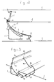
- Fig. 1 is a perspective view of a shade section and a part of a shade, with a number of clamping brackets thereon;
- Fig. 2 is a cross-section of Fig. 1; and
- Figs. 3 and 4 show variants of Fig. 1.
- A shade section extruded from aluminium is indicated by 1 and generally runs horizontally in a greenhouse or glasshouse at the level of the gutters.
- A section of this type is known in practice and is moved parallel to itself in order to open or to close a
flexible shade 2 made of cloth or sheeting. - In the closed position the shade section rests with the left side against a fixed bar of the greenhouse or glasshouse. Such bars (not shown) run parallel to each other and are disposed at specific distances from each other as part of the frame of the greenhouse.
- The shade section 1 can be moved parallel to itself in the horizontal direction. On movement to the left the
shade 2 is folded out, so that the space in the greenhouse below theshade 2 is better shut off from temperature variations. - When the shade has to be opened the shade section 1 is moved to the right and the
shade 2 folds up. - Nylon cords are pulled taut between the bars in the greenhouse in order to ensure that the folded
shade 2 does not project too much. - The top taut cords are indicated by 3, and the bottom cords by 4.
- The bottom cords 4 serve to support the weight of the folded
shade 2, and thetop cords 3 to prevent flying up when the ventilation windows are open. - The right end of the
shade 2 is fixed at the right side to a fixed bar which is a distance away from the fixed bar against which the shade section 1 rests when theshade 2 is closed. - According to the state of the art,
brackets 5 made of resilient metal wire are used as a guide along thecords 3 and 4. One such knownbracket 5 is shown on the right in Fig. 1, is clamped around theedges 1a and 1b of the section 1, and forms a wide opening for thecord 3. - In the state of the art the
same brackets 5 are clamped around theedges 1c and 1d of the section 1, and then form a wide opening for the cord 4. - Every known shade section 1 thus has a large number of
such brackets 5, the number on the top side generally being half the number on the bottom side. - The known shade sections also have a projecting edge 6 with thickened
end 7, which is shown by dot-and-dash lines in Fig. 2. - The left edge of the
shade 2 is then folded round the thickenedend 7 and the shade is fixed by means of a sort of clip on the projectingedge 6, 7. These clips are generally made of plastic and when fitted clamp the folded edge of theshade 2 against the projectingedge 6, 7. - In the growing of some crops the
shade 2 is sometimes removed completely after only a short time. The folded shade in that case still gives too much light loss and thus loss of yield. For removal of the shade, it is simply pulled away from the projectingedge 6, 7, in which case the clips spring off and are lost, but also fall between the crops. - According to the application, no clips need be used and the projecting
edge 6, 7 can be omitted. - According to the invention, the brackets used for guiding along the
cords 3 and 4 are modified in such a way that they can also be used for fixing the shade to the section 1. - Such a bracket is indicated by 8 on the left in Fig. 1. This
bracket 8 is largely the same as the knownbracket 5, but oneleg 8a is extended and bent back, while thefree end 8b grips behind the edge 1c of the section 1. - The bent-
back leg 8a is so long that the bend 8c rests resiliently against the edge 1b of the section 1. - The free edge 2a of the
shade 2 is then laid in the channel formed by the edge 1b, and the bend 8c of thebracket 8 presses the free edge 2a against the channel. - No separate clips are therefore needed.
- In addition, the
brackets 8 remain on the section 1 when theshade 2 is pulled away from the section 1. - The free edge 2a of the
shade 2 can also engage in the channel formed by the edge 1c and is then pressed by abracket 8 which also engages on theedges 1a and 1b of the section 1. - This is possible because the section 1 is to a certain extent symmetrical, i.e. the distance between the
edges 1d and 1b is equal to the distance between theedges 1a and 1c, and theedge 6, 7 is omitted. - According to the invention, the
shade 2 is fixed at such a point on the section 1 that as little light loss as possible occurs. - The bracket can, of course, also be made differently.
- Another embodiment of the clamping bracket is shown in Fig. 3 in a perspective view. This clamping bracket is indicated by 9 and largely corresponds to the
clamping bracket 8, except that the right leg is different. - The extended
leg 9a is first folded inwards at 9b, in order to engage behind the edge 1c of the section 1, and then runs into a curved edge 9c which can clamp the edge of theshade 2 in the channel formed by the edge 1b of the section 1, in the same way as the bend 8c of thebracket 8. - Yet another embodiment of the clamping bracket is shown in Fig. 4 and is indicated by 10. The
bracket 10 has features of thebracket 8 and of the bracket 9, and is preferred. - The right leg of the
bracket 10 is conventional. - The
left leg 10a is first folded around the edge 1c, like the bracket 9 at 10b. At 10c theleg 10a is folded back and with thefree end 10d engages in the channel formed by the edge 1c.
Claims (5)
- A bracket of resilient metal wire intended for fixing to a section of a shading structure in a greenhouse or glasshouse, the section having a first and a second surface mutually spaced at approximately 90°, said first surface defining a second (1b) free edge facing the second surface and said second surface defining third (1c) and fourth (1d) mutually oppositely directed free edges, said second and third free edges being mutually closer than said second and fourth free edge, channel sections adjoining said second and third free edges to allow portions of the bracket to engage under said second and third free edges, the section defining an uninterrupted span between the two channels, and being for instance according to claim 4, said bracket (8; 9; 10) having mutually spaced first and second legs interconnected at one end by a crosspiece, the bracket thereby being in an essentially U-shaped form and said legs lying partly in a common plane, each leg having a first bend out of, and in one direction generally perpendicular to said common plane, to form a first hook portion for engagement with the fourth free edge of said section, at least one leg having at a distance from said first bend a second bend in a direction opposite to that of said first bend in order to define a second hook portion for engagement with the third free edge of said section, the other leg having at least one portion (8b; 9b; 10b) for engagement under the third free edge of said section, characterised in that said other leg also has at least one portion (8c; 9c; 10c) for engagement under the second free edge of said section, said portion for engaging under said second free edge being located on an extension (8a; 9a; 10a) of said other leg located beyond said distance from said first bend.
- Bracket according to claim 1, wherein said extension is loop-shaped, such that two wire parts run between the second hook profile (1b) and the first hook profile (1c), with the free end of the second leg engaging the third hook profile (1c).
- Bracket according to claim 1 or 2, wherein apart from the extension (8a;9a;10a) of the second leg, said first and second legs have a substantial similar shape.
- A section for accommodating brackets according to any one of the preceding claims, having a first and a second surface mutually spaced at approximately 90°, said first surface defining first (1a) and second (1b) mutually oppositely directed free edges and said second surface defining third (1c) and fourth (1d) mutually oppositely directed free edges, said second and third free edges being mutually closer than said first and fourth free edges, channel sections adjoining said second and third free edges to allow portions of the bracket to engage under said second and third free edges, characterised in that the distance between the first edge and the base of the third edge channel is equal to the distance between the fourth edge and the base of the second edge channel, the distances between the first and second edges and the third and fourth edges respectively being equal whereby the bracket may be mounted on either the first or second surface with the extension engaging the third edge channel or the second edge channel respectively, the section defining an uninterrupted span between the two channels to allow the bracket extension to locate between one channel and the other channel or its associated edge.
- Section according to Claim 4, wherein said fixing planes are staggered with respect to the mutual leg of said section, to the side facing the opposite fixing plane, and each fixing plane laterally extending on either side of the connection position with the mutual leg of said section.
Applications Claiming Priority (2)
| Application Number | Priority Date | Filing Date | Title |
|---|---|---|---|
| NL9000479 | 1990-02-28 | ||
| NL9000479A NL9000479A (en) | 1990-02-28 | 1990-02-28 | BRACKET AND PROFILE INTENDED FOR ATTACHING A HORIZONTAL SCREEN IN A GREENHOUSE OR WAREHOUSE. |
Publications (2)
| Publication Number | Publication Date |
|---|---|
| EP0444743A1 EP0444743A1 (en) | 1991-09-04 |
| EP0444743B1 true EP0444743B1 (en) | 1995-05-03 |
Family
ID=19856678
Family Applications (1)
| Application Number | Title | Priority Date | Filing Date |
|---|---|---|---|
| EP91200384A Expired - Lifetime EP0444743B1 (en) | 1990-02-28 | 1991-02-22 | Bracket and section intended for fixing a horizontal shade in a greenhouse or glasshouse |
Country Status (3)
| Country | Link |
|---|---|
| EP (1) | EP0444743B1 (en) |
| DE (1) | DE69109349T2 (en) |
| NL (1) | NL9000479A (en) |
Cited By (1)
| Publication number | Priority date | Publication date | Assignee | Title |
|---|---|---|---|---|
| NL1014244C2 (en) * | 2000-02-01 | 2001-08-03 | Valk Systemen Bvvd | Screen device in greenhouse comprises columns supporting ceiling and has at least one profile suspended and displaceable crossways to its longitudinal direction in greenhouse |
Families Citing this family (5)
| Publication number | Priority date | Publication date | Assignee | Title |
|---|---|---|---|---|
| NL1033715C2 (en) * | 2007-02-13 | 2008-08-14 | Metaal En Kunststoffen Ind Sne | Mounting clip for greenhouse screen profile, includes guides cooperating with screen cloth tensioning wires and fastener for securing to screen cloth |
| DE202008013436U1 (en) | 2008-10-13 | 2009-01-29 | Novavert Gmbh & Co. Kg | Greenhouse with shading device and fixing profile |
| NL2002321C2 (en) | 2008-12-12 | 2010-06-15 | Valk Systemen Bvvd | SET OUT ON SHARP PROFILES STACKED TOGETHER, COMPOSITION FROM MULTIPLE SETS OF THIS AND ANY SHARP PROFILE. |
| NL2004130C2 (en) * | 2010-01-22 | 2012-03-05 | Bordeso Bv | SCREEN SYSTEM FOR A WAREHOUSE. |
| DE202014103105U1 (en) | 2013-11-20 | 2014-08-12 | Werner Heinze | clamp |
Citations (1)
| Publication number | Priority date | Publication date | Assignee | Title |
|---|---|---|---|---|
| EP0338925A1 (en) * | 1988-04-22 | 1989-10-25 | Fernand Scherrer | False ceiling comprising a tensioned sheet secured along its edges to a support fixed to the wall of a room of a building |
Family Cites Families (1)
| Publication number | Priority date | Publication date | Assignee | Title |
|---|---|---|---|---|
| US3719013A (en) * | 1971-02-12 | 1973-03-06 | O Blick | Moulding for suspension mounting and decoration purposes |
-
1990
- 1990-02-28 NL NL9000479A patent/NL9000479A/en not_active Application Discontinuation
-
1991
- 1991-02-22 DE DE69109349T patent/DE69109349T2/en not_active Expired - Fee Related
- 1991-02-22 EP EP91200384A patent/EP0444743B1/en not_active Expired - Lifetime
Patent Citations (1)
| Publication number | Priority date | Publication date | Assignee | Title |
|---|---|---|---|---|
| EP0338925A1 (en) * | 1988-04-22 | 1989-10-25 | Fernand Scherrer | False ceiling comprising a tensioned sheet secured along its edges to a support fixed to the wall of a room of a building |
Cited By (1)
| Publication number | Priority date | Publication date | Assignee | Title |
|---|---|---|---|---|
| NL1014244C2 (en) * | 2000-02-01 | 2001-08-03 | Valk Systemen Bvvd | Screen device in greenhouse comprises columns supporting ceiling and has at least one profile suspended and displaceable crossways to its longitudinal direction in greenhouse |
Also Published As
| Publication number | Publication date |
|---|---|
| NL9000479A (en) | 1991-09-16 |
| EP0444743A1 (en) | 1991-09-04 |
| DE69109349T2 (en) | 1996-01-04 |
| DE69109349D1 (en) | 1995-06-08 |
Similar Documents
| Publication | Publication Date | Title |
|---|---|---|
| US4907783A (en) | Chain link fence edging and trimming attachment | |
| US4518025A (en) | Sun blind construction | |
| US4673018A (en) | Sun blind | |
| US5141192A (en) | Apparatus for hanging cords from a gutter or the like | |
| AU604230B2 (en) | False ceiling or false wall constituted by a stretched sheet fastened | |
| DE3775406D1 (en) | Waescheaufhaengevorrichtung. | |
| US4457106A (en) | Shutter system | |
| MX2007005186A (en) | Single-track stacking panel covering for an architectural opening. | |
| US5275381A (en) | Wire fencing with decorative slats that provide essentially complete privacy | |
| EP0444743B1 (en) | Bracket and section intended for fixing a horizontal shade in a greenhouse or glasshouse | |
| CA1225582A (en) | Drapery support and traverse system | |
| US6739374B1 (en) | Method and apparatus for retaining slats of a vertical blind | |
| US4793396A (en) | Adjustable fabric retainer for a window blind | |
| US1899062A (en) | Splint shade support | |
| US6935078B1 (en) | Anchor fastener clip | |
| US4237958A (en) | Drapery connector assembly | |
| US3971427A (en) | Venetian blind profiled slats | |
| US6173544B1 (en) | Ceiling system and also a lath suitable for such a ceiling system | |
| US2785445A (en) | Plastic awning construction | |
| US3470578A (en) | Drapery rod and bracket | |
| EP0569355B1 (en) | A cloth hanger clip and a fabric intended to be used together with the clip | |
| KR101042754B1 (en) | Curtain system comprising several flat panels | |
| JPS6119644Y2 (en) | ||
| US4706433A (en) | Suspended ceiling assembly | |
| CA2359515C (en) | Apparatus for connecting and anchoring tarpaulins |
Legal Events
| Date | Code | Title | Description |
|---|---|---|---|
| PUAI | Public reference made under article 153(3) epc to a published international application that has entered the european phase |
Free format text: ORIGINAL CODE: 0009012 |
|
| AK | Designated contracting states |
Kind code of ref document: A1 Designated state(s): BE DE GB NL |
|
| 17P | Request for examination filed |
Effective date: 19911213 |
|
| 17Q | First examination report despatched |
Effective date: 19921208 |
|
| GRAA | (expected) grant |
Free format text: ORIGINAL CODE: 0009210 |
|
| AK | Designated contracting states |
Kind code of ref document: B1 Designated state(s): BE DE GB NL |
|
| REF | Corresponds to: |
Ref document number: 69109349 Country of ref document: DE Date of ref document: 19950608 |
|
| PLBE | No opposition filed within time limit |
Free format text: ORIGINAL CODE: 0009261 |
|
| STAA | Information on the status of an ep patent application or granted ep patent |
Free format text: STATUS: NO OPPOSITION FILED WITHIN TIME LIMIT |
|
| 26N | No opposition filed | ||
| REG | Reference to a national code |
Ref country code: GB Ref legal event code: IF02 |
|
| PGFP | Annual fee paid to national office [announced via postgrant information from national office to epo] |
Ref country code: GB Payment date: 20020204 Year of fee payment: 12 |
|
| NLT1 | Nl: modifications of names registered in virtue of documents presented to the patent office pursuant to art. 16 a, paragraph 1 |
Owner name: VAN DER VALK SYSTEMEN B.V. |
|
| PG25 | Lapsed in a contracting state [announced via postgrant information from national office to epo] |
Ref country code: GB Free format text: LAPSE BECAUSE OF NON-PAYMENT OF DUE FEES Effective date: 20030222 |
|
| GBPC | Gb: european patent ceased through non-payment of renewal fee | ||
| PGFP | Annual fee paid to national office [announced via postgrant information from national office to epo] |
Ref country code: DE Payment date: 20080310 Year of fee payment: 18 |
|
| PG25 | Lapsed in a contracting state [announced via postgrant information from national office to epo] |
Ref country code: DE Free format text: LAPSE BECAUSE OF NON-PAYMENT OF DUE FEES Effective date: 20090901 |
|
| PGFP | Annual fee paid to national office [announced via postgrant information from national office to epo] |
Ref country code: BE Payment date: 20100222 Year of fee payment: 20 |
|
| BE20 | Be: patent expired |
Owner name: *VAN DER VALK SYSTEMEN B.V. Effective date: 20110222 |
|
| REG | Reference to a national code |
Ref country code: NL Ref legal event code: V4 Effective date: 20110222 |
|
| PG25 | Lapsed in a contracting state [announced via postgrant information from national office to epo] |
Ref country code: NL Free format text: LAPSE BECAUSE OF EXPIRATION OF PROTECTION Effective date: 20110222 |
|
| PGFP | Annual fee paid to national office [announced via postgrant information from national office to epo] |
Ref country code: NL Payment date: 20100228 Year of fee payment: 20 |