EP0444575A2 - Shielded magnetoelastic torque transducer - Google Patents
Shielded magnetoelastic torque transducer Download PDFInfo
- Publication number
- EP0444575A2 EP0444575A2 EP91102738A EP91102738A EP0444575A2 EP 0444575 A2 EP0444575 A2 EP 0444575A2 EP 91102738 A EP91102738 A EP 91102738A EP 91102738 A EP91102738 A EP 91102738A EP 0444575 A2 EP0444575 A2 EP 0444575A2
- Authority
- EP
- European Patent Office
- Prior art keywords
- shaft
- transducer
- magnetic
- flanges
- shielded
- Prior art date
- Legal status (The legal status is an assumption and is not a legal conclusion. Google has not performed a legal analysis and makes no representation as to the accuracy of the status listed.)
- Granted
Links
Images
Classifications
-
- G—PHYSICS
- G01—MEASURING; TESTING
- G01L—MEASURING FORCE, STRESS, TORQUE, WORK, MECHANICAL POWER, MECHANICAL EFFICIENCY, OR FLUID PRESSURE
- G01L3/00—Measuring torque, work, mechanical power, or mechanical efficiency, in general
- G01L3/02—Rotary-transmission dynamometers
- G01L3/04—Rotary-transmission dynamometers wherein the torque-transmitting element comprises a torsionally-flexible shaft
- G01L3/10—Rotary-transmission dynamometers wherein the torque-transmitting element comprises a torsionally-flexible shaft involving electric or magnetic means for indicating
- G01L3/101—Rotary-transmission dynamometers wherein the torque-transmitting element comprises a torsionally-flexible shaft involving electric or magnetic means for indicating involving magnetic or electromagnetic means
- G01L3/102—Rotary-transmission dynamometers wherein the torque-transmitting element comprises a torsionally-flexible shaft involving electric or magnetic means for indicating involving magnetic or electromagnetic means involving magnetostrictive means
-
- G—PHYSICS
- G01—MEASURING; TESTING
- G01L—MEASURING FORCE, STRESS, TORQUE, WORK, MECHANICAL POWER, MECHANICAL EFFICIENCY, OR FLUID PRESSURE
- G01L3/00—Measuring torque, work, mechanical power, or mechanical efficiency, in general
- G01L3/02—Rotary-transmission dynamometers
- G01L3/04—Rotary-transmission dynamometers wherein the torque-transmitting element comprises a torsionally-flexible shaft
- G01L3/10—Rotary-transmission dynamometers wherein the torque-transmitting element comprises a torsionally-flexible shaft involving electric or magnetic means for indicating
- G01L3/101—Rotary-transmission dynamometers wherein the torque-transmitting element comprises a torsionally-flexible shaft involving electric or magnetic means for indicating involving magnetic or electromagnetic means
- G01L3/105—Rotary-transmission dynamometers wherein the torque-transmitting element comprises a torsionally-flexible shaft involving electric or magnetic means for indicating involving magnetic or electromagnetic means involving inductive means
-
- Y—GENERAL TAGGING OF NEW TECHNOLOGICAL DEVELOPMENTS; GENERAL TAGGING OF CROSS-SECTIONAL TECHNOLOGIES SPANNING OVER SEVERAL SECTIONS OF THE IPC; TECHNICAL SUBJECTS COVERED BY FORMER USPC CROSS-REFERENCE ART COLLECTIONS [XRACs] AND DIGESTS
- Y10—TECHNICAL SUBJECTS COVERED BY FORMER USPC
- Y10T—TECHNICAL SUBJECTS COVERED BY FORMER US CLASSIFICATION
- Y10T29/00—Metal working
- Y10T29/49—Method of mechanical manufacture
- Y10T29/49002—Electrical device making
- Y10T29/4902—Electromagnet, transformer or inductor
Definitions
- the invention relates to a shielded magnetoelastic torque transducer according to the precharacterising part of claim 1. Shielding is provided against static or quasistatic magnetic fields axially extending in the shaft between the driving source and the driven load.
- magnetoelastic transducers are based on the measurement of the permeability change which takes place in a ferromagnetic material when subjected to mechanical stress.
- the measuring principles and configuration of these transducers are well known and described in a plurality of publications and patent specifications, inter alia in EP-A-89,916, US-A-4,506,554 and SE-A-8,904,307-9, the latter corresponding to EP-A-90,195,168.6.
- a magnetoelastic torque transducer comprises a transducer shaft and a stationary casing comprising a magnetic core as well as excitation and measuring windings attached to said core. A detailed description thereof need not be given here.
- the magnetic hysteresis curve that is, the flux-density-versa-magnetic-field-strength-curve (B-H curve), traversed by each point in the material during a cycle of the magnetization, will be changed when the material is, in addition, magnetized by a static field.
- B-H curve flux-density-versa-magnetic-field-strength-curve
- the differential permeability as well as the sensitivity of the transducer will be very low. However, the detrimental influence is also present in connection with considerably lower field strengths.
- the traditional method is to surround the transducer with a magnetic shield made of highly magnetically permeable material, for example of mu-metal.
- a magnetic shield made of highly magnetically permeable material, for example of mu-metal.
- such a design mainly serves as a shield against magnetic fields in the air which are directed across the transducer shaft.
- a torque transducer forms a link in a torque transmission between a driving source and a load.
- a remanent axial magnetic field in some of the parts in this transmission may then be conducted directly into the transducer shaft without being diverted by the external shield.
- the transducer shaft of magnetic material constitutes part of the magnetic shaft which connects the driving source to the driven load. If in some way a magnetic flux with a component in the longitudinal direction of the shaft may enter the shaft, this flux will therefore also pass through the transducer shaft and is able to influence the torque measurement in the manner described. As explained above, a shield surrounding the transducer will not be able to divert this magnetic flux in the shaft from the transducer.
- the invention aims at developing a shielded magnetoelastic torque transducer of the above-mentioned kind which is capable to shield off external magnetic fields that extend in the longitudinal direction within the shafts connected to the torque transducer.
- the invention suggests a shielded magnetoelastic torque transducer according to the introductory part of claim 1, which is characterized by the features of the characterizing part of claim 1.
- the driving shaft between the driving source and the load is divided in such a way that the part between the driving source and the transducer shaft and part between the transducer shaft and the load, respectively, are made of non-magnetic material.
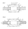
- Figure 1 shows an example of the state of the art for protecting a torque transducer against an external magnetic field 6 present in the ambient space and directed perpendicular to the transducer shaft.
- the transducer shaft 1 is surrounded by a stationary casing 2 of the transducer which houses the windings etc.
- Welded or otherwise fixed to one end of the transducer shaft is a first shaft part 3 towards a driving source, and, in similar manner, fixed to the other end of the transducer shaft is a second shaft part 4 towards the driven load.
- a soft-magnetic shield 5 then protects the transducer against the external magnetic field 6 directed perpendicular to the transducer shaft.
- FIG. 2 shows a transducer shaft, a casing 2, shaft parts 3 and 4 towards the driving source and towards the driven load, respectively, and a surrounding magnetic shield 5.
- a transducer shaft and the previously mentioned first shaft part 3 towards the driving source and between the transducer shaft and the previously mentioned second shaft part 4 towards the driven load respectively, a third shaft part 7 and a fourth shaft part 8, respectively, of non-magnetic material are inserted.
- the flanges 10, 11 are located opposite the shaft parts 7, 8 of non-magnetic material.
- the effect of the short-circuiting function of the shield 5 with its flanges may be further increased by locating the flanges such that they face portions of the shaft parts 3 and 4, respectively, of magnetic material.
Landscapes
- Physics & Mathematics (AREA)
- Electromagnetism (AREA)
- General Physics & Mathematics (AREA)
- Shafts, Cranks, Connecting Bars, And Related Bearings (AREA)
- Force Measurement Appropriate To Specific Purposes (AREA)
- Transmission And Conversion Of Sensor Element Output (AREA)
- Details Of Measuring And Other Instruments (AREA)
Abstract
Description
- The invention relates to a shielded magnetoelastic torque transducer according to the precharacterising part of claim 1. Shielding is provided against static or quasistatic magnetic fields axially extending in the shaft between the driving source and the driven load.
- As is well known, magnetoelastic transducers are based on the measurement of the permeability change which takes place in a ferromagnetic material when subjected to mechanical stress. The measuring principles and configuration of these transducers are well known and described in a plurality of publications and patent specifications, inter alia in EP-A-89,916, US-A-4,506,554 and SE-A-8,904,307-9, the latter corresponding to EP-A-90,195,168.6. Briefly, it may be stated that a magnetoelastic torque transducer comprises a transducer shaft and a stationary casing comprising a magnetic core as well as excitation and measuring windings attached to said core. A detailed description thereof need not be given here.
- Regardless of which method is used to measure the permeability changes, the magnetic hysteresis curve, that is, the flux-density-versa-magnetic-field-strength-curve (B-H curve), traversed by each point in the material during a cycle of the magnetization, will be changed when the material is, in addition, magnetized by a static field. This, of course, influences the measurement and leads to changes of the measured signal in case of an unloaded transducer, that is the zero signal, and of the sensitivity of the transducer to the influence of forces.
- If the transducer is so heavily magnetized by a static field that the ferromagnetic material approaches saturation, the differential permeability as well as the sensitivity of the transducer will be very low. However, the detrimental influence is also present in connection with considerably lower field strengths.
- To reduce the effect of external static fields, attempts have been made to shield off such fields. However, this has proved to be a difficult technical problem. The traditional method is to surround the transducer with a magnetic shield made of highly magnetically permeable material, for example of mu-metal. However, such a design mainly serves as a shield against magnetic fields in the air which are directed across the transducer shaft.
- However, according to the above, a torque transducer forms a link in a torque transmission between a driving source and a load. A remanent axial magnetic field in some of the parts in this transmission may then be conducted directly into the transducer shaft without being diverted by the external shield.
- The problem with static external magnetization may become particularly serious since static magnetization, by remanence in the transducer material, may also give rise to permanent changes in the operation of the transducer.
- The above-mentioned SE-A-8,904,307-9 discloses an electrical method of minimizing the effect of an external static or quasi-static magnetic field. The method is based on the fact that an external magnetic field causes the measured signal to comprise even harmonics, together with the odd harmonics of the fundamental wave of the magnetization. The magnitude of the even harmonics is a measure of the magnitude of the external magnetic field. By measuring the even harmonics and using this as an input signal to a regulator, the external magnetization may be reduced to zero with the aid of direct current in some suitable winding.
- The transducer shaft of magnetic material constitutes part of the magnetic shaft which connects the driving source to the driven load. If in some way a magnetic flux with a component in the longitudinal direction of the shaft may enter the shaft, this flux will therefore also pass through the transducer shaft and is able to influence the torque measurement in the manner described. As explained above, a shield surrounding the transducer will not be able to divert this magnetic flux in the shaft from the transducer.
- The invention aims at developing a shielded magnetoelastic torque transducer of the above-mentioned kind which is capable to shield off external magnetic fields that extend in the longitudinal direction within the shafts connected to the torque transducer.
- To achieve this aim the invention suggests a shielded magnetoelastic torque transducer according to the introductory part of claim 1, which is characterized by the features of the characterizing part of claim 1.
- Further developments of the invention are characterized by the features of the additional claims.
- According to the invention the driving shaft between the driving source and the load is divided in such a way that the part between the driving source and the transducer shaft and part between the transducer shaft and the load, respectively, are made of non-magnetic material. By providing the transducer and the transducer shaft, including the non-magnetic shaft parts, with an external magnetic shield with flanges so that there will be a very small air gap between the flanges of the shield and the periphery of the non-magnetic shaft parts, an axial magnetic flux will be conducted past the transducer through the external magnetic shield.
- By way of example, the invention will now be described in greater detail with reference to the accompanying drawings showing in
- Figure 1
- the application of a shield around a magnetoelastic torque transducer according to the state of the art,
- Figure 2
- a torque transducer according to the invention, protected against an external static or quasistatic magnetic field.
- Figure 1 shows an example of the state of the art for protecting a torque transducer against an external magnetic field 6 present in the ambient space and directed perpendicular to the transducer shaft. The transducer shaft 1 is surrounded by a
stationary casing 2 of the transducer which houses the windings etc. Welded or otherwise fixed to one end of the transducer shaft is afirst shaft part 3 towards a driving source, and, in similar manner, fixed to the other end of the transducer shaft is a second shaft part 4 towards the driven load. A soft-magnetic shield 5 then protects the transducer against the external magnetic field 6 directed perpendicular to the transducer shaft. - A preferred embodiment according to the invention for shielding the transducer from an axial magnetic field 9 extending within the shaft between the driving source and the load is shown in Figure 2. In the same way as in Figure 1 and with the same reference numerals, Figure 2 shows a transducer shaft, a
casing 2,shaft parts 3 and 4 towards the driving source and towards the driven load, respectively, and a surroundingmagnetic shield 5. Specific to the invention, as described above is that between the transducer shaft and the previously mentionedfirst shaft part 3 towards the driving source and between the transducer shaft and the previously mentioned second shaft part 4 towards the driven load, respectively, a third shaft part 7 and afourth shaft part 8, respectively, of non-magnetic material are inserted. A consequence of this is that any magnetic flux extending in the shaft and represented by the lines 9, as regards the transducer region, pass through the surroundingmagnetic shield 5 provided withflanges - In Figure 2 the
flanges shaft parts 7, 8 of non-magnetic material. The effect of the short-circuiting function of theshield 5 with its flanges may be further increased by locating the flanges such that they face portions of theshaft parts 3 and 4, respectively, of magnetic material.
Claims (4)
- Shielded magnetoelastic torque transducer for shielding off static of quasi-static external magnetic fields, with a stationary casing (2), which houses a magnetic core with excitation and measuring windings and a transducer shaft (1), with a first shaft part (3) between said transducer shaft and a driving source, and with a second shaft part (4) between said transducer shaft and a driven load, characterized in that between the transducer shaft and the first shaft part (3) there is attached a third shaft part (7) of non-magnetic material, that between the transducer shaft and the second shaft part (4) there is attached a fourth shaft part (8) of non-magnetic material, and that the casing (2), the transducer shaft and the non-magnetic shaft parts (7,8) are surrounded by a magnetic shield (5) of soft-magnetic material formed with flanges (10, 11) which extend towards the shaft.
- Shielded magnetoelastic torque transducer according to claim 1, characterized in that the air gaps (12) formed between the shield flanges (10,11) and the shaft are as small as possible.
- Shielded magnetoelastic torque transducer according to claim 1 or 2, characterized in that the shield (5) and/or its flanges (10, 11) are formed and dimensioned such that the air gaps (12) are formed between said flanges and the shaft parts (7,8) of non-magnetic material.
- Shielded magnetoelastic torque transducer according to claim 1 or 2, characterized in that the shield (5) and/or its flanges (10, 11) are formed and dimensioned such that the air gaps (12) are formed between said flanges (10, 11) and the first shaft part (3) between the shaft parts (7) of non-magnetic material and the driving source, and the second shaft part (4) between the shaft parts (8) of non-magnetic material and the load, respectively.
Applications Claiming Priority (2)
| Application Number | Priority Date | Filing Date | Title |
|---|---|---|---|
| SE9000716 | 1990-02-28 | ||
| SE9000716A SE465942B (en) | 1990-02-28 | 1990-02-28 | PROCEDURE TO SCREEN MAGNETOELASTIC SENSORS |
Publications (3)
| Publication Number | Publication Date |
|---|---|
| EP0444575A2 true EP0444575A2 (en) | 1991-09-04 |
| EP0444575A3 EP0444575A3 (en) | 1992-06-03 |
| EP0444575B1 EP0444575B1 (en) | 1994-12-14 |
Family
ID=20378717
Family Applications (1)
| Application Number | Title | Priority Date | Filing Date |
|---|---|---|---|
| EP91102738A Expired - Lifetime EP0444575B1 (en) | 1990-02-28 | 1991-02-25 | Shielded magnetoelastic torque transducer |
Country Status (5)
| Country | Link |
|---|---|
| US (1) | US5083359A (en) |
| EP (1) | EP0444575B1 (en) |
| JP (1) | JP3110774B2 (en) |
| DE (1) | DE69105775T2 (en) |
| SE (1) | SE465942B (en) |
Cited By (4)
| Publication number | Priority date | Publication date | Assignee | Title |
|---|---|---|---|---|
| WO1998025116A1 (en) * | 1996-12-04 | 1998-06-11 | Koninklijke Philips Electronics N.V. | Magnetoelastic torque sensor with shielding flux guide |
| US6330833B1 (en) | 1997-03-28 | 2001-12-18 | Mannesmann Vdo Ag | Magnetoelastic torque sensor |
| EP1464936A3 (en) * | 2003-04-02 | 2004-11-24 | HONDA MOTOR CO., Ltd. | Torque sensor |
| WO2008034890A3 (en) * | 2006-09-22 | 2008-07-24 | Continental Automotive Gmbh | Device for detecting a force and/or a torque |
Families Citing this family (8)
| Publication number | Priority date | Publication date | Assignee | Title |
|---|---|---|---|---|
| US5255567A (en) * | 1990-06-30 | 1993-10-26 | Nippon Densan Corporation | Torque transducer |
| US6105236A (en) * | 1998-02-05 | 2000-08-22 | Raytheon Company | Magnetic structure for minimizing AC resistance in planar rectangular conductors |
| JP2005043160A (en) * | 2003-07-25 | 2005-02-17 | Hitachi Unisia Automotive Ltd | Rotation detection sensor |
| JP2007121149A (en) * | 2005-10-28 | 2007-05-17 | Jtekt Corp | Torque detection device |
| US8087304B2 (en) * | 2008-03-14 | 2012-01-03 | Seong-Jae Lee | Magnetoelastic torque sensor with ambient field rejection |
| US8001849B2 (en) * | 2009-03-28 | 2011-08-23 | Wensheng Weng | Self-compensating magnetoelastic torque sensor system |
| AU2013200469B2 (en) * | 2012-02-07 | 2016-03-24 | Methode Electronics, Inc. | Magnetic torque sensor for transmission converter drive plate |
| CN106737202A (en) * | 2016-12-26 | 2017-05-31 | 株洲九方装备股份有限公司 | A kind of machining magnetic field shielding method and device containing permanent magnet workpiece |
Family Cites Families (3)
| Publication number | Priority date | Publication date | Assignee | Title |
|---|---|---|---|---|
| JPS58159720A (en) * | 1982-03-19 | 1983-09-22 | オリンパス光学工業株式会社 | Apparatus for detecting water leakage for endoscope |
| JPS61247932A (en) * | 1985-04-26 | 1986-11-05 | Matsushita Electric Ind Co Ltd | Torque sensor |
| DE8903560U1 (en) * | 1989-03-21 | 1989-05-18 | Siemens AG, 1000 Berlin und 8000 München | Torque measuring sensor |
-
1990
- 1990-02-28 SE SE9000716A patent/SE465942B/en not_active IP Right Cessation
-
1991
- 1991-02-25 DE DE69105775T patent/DE69105775T2/en not_active Expired - Fee Related
- 1991-02-25 EP EP91102738A patent/EP0444575B1/en not_active Expired - Lifetime
- 1991-02-26 US US07/660,844 patent/US5083359A/en not_active Expired - Lifetime
- 1991-02-27 JP JP03033038A patent/JP3110774B2/en not_active Expired - Fee Related
Cited By (6)
| Publication number | Priority date | Publication date | Assignee | Title |
|---|---|---|---|---|
| WO1998025116A1 (en) * | 1996-12-04 | 1998-06-11 | Koninklijke Philips Electronics N.V. | Magnetoelastic torque sensor with shielding flux guide |
| US6330833B1 (en) | 1997-03-28 | 2001-12-18 | Mannesmann Vdo Ag | Magnetoelastic torque sensor |
| US6598491B2 (en) | 1997-03-28 | 2003-07-29 | John E. Opie | Magnetoelastic torque sensor |
| EP1464936A3 (en) * | 2003-04-02 | 2004-11-24 | HONDA MOTOR CO., Ltd. | Torque sensor |
| US7013741B2 (en) | 2003-04-02 | 2006-03-21 | Honda Motor Co., Ltd. | Torque sensor |
| WO2008034890A3 (en) * | 2006-09-22 | 2008-07-24 | Continental Automotive Gmbh | Device for detecting a force and/or a torque |
Also Published As
| Publication number | Publication date |
|---|---|
| US5083359A (en) | 1992-01-28 |
| DE69105775D1 (en) | 1995-01-26 |
| SE465942B (en) | 1991-11-18 |
| EP0444575A3 (en) | 1992-06-03 |
| DE69105775T2 (en) | 1995-07-27 |
| JPH04216428A (en) | 1992-08-06 |
| JP3110774B2 (en) | 2000-11-20 |
| EP0444575B1 (en) | 1994-12-14 |
| SE9000716D0 (en) | 1990-02-28 |
| SE9000716L (en) | 1991-08-29 |
Similar Documents
| Publication | Publication Date | Title |
|---|---|---|
| US4045738A (en) | Variable reluctance speed sensor of integral construction utilizing a shielded high coercive force rare earth magnet positioned directly adjacent the sensing rotating element | |
| EP0444575B1 (en) | Shielded magnetoelastic torque transducer | |
| US4150314A (en) | Level amplitude output rotary speed transducer | |
| EP0525551B1 (en) | Circularly magnetized non-contact torque sensor,method, and transducer ring | |
| US3932813A (en) | Eddy current sensor | |
| EP1070237B1 (en) | Magnetic force sensor and method for its manufacture | |
| EP0829001B1 (en) | Circularly magnetized non-contact torque and power sensor and method for measuring torque and power using same | |
| US6698299B2 (en) | Magnetoelastic torque sensor | |
| US4986137A (en) | Strain detector with magnetostrictive elements | |
| US4891992A (en) | Torque detecting apparatus | |
| US20070227268A1 (en) | Magnetostrictive torque sensor | |
| JPH01187424A (en) | Torque sensor | |
| US5194805A (en) | Inductance-type displacement sensor for eliminating inaccuracies due to external magnetic fields | |
| JP2608498B2 (en) | Magnetostrictive torque sensor | |
| US4651573A (en) | Shaft torquemeter | |
| JP2566640B2 (en) | Torque measuring device | |
| JPH1194658A (en) | Torque sensor | |
| JP2000009557A (en) | Torque sensor | |
| JPS6161026A (en) | shaft torque meter | |
| JPH02154130A (en) | distortion detector | |
| JPS61294322A (en) | Torque detection device | |
| JPH0454322A (en) | Magnetic particle type electromagnetic coupling device | |
| JPS6050429A (en) | Torque sensor | |
| US2967426A (en) | Force measuring device | |
| SU892242A2 (en) | Device for measuring torques |
Legal Events
| Date | Code | Title | Description |
|---|---|---|---|
| PUAI | Public reference made under article 153(3) epc to a published international application that has entered the european phase |
Free format text: ORIGINAL CODE: 0009012 |
|
| AK | Designated contracting states |
Kind code of ref document: A2 Designated state(s): DE FR GB IT |
|
| PUAL | Search report despatched |
Free format text: ORIGINAL CODE: 0009013 |
|
| AK | Designated contracting states |
Kind code of ref document: A3 Designated state(s): DE FR GB IT |
|
| 17P | Request for examination filed |
Effective date: 19921127 |
|
| 17Q | First examination report despatched |
Effective date: 19940203 |
|
| GRAA | (expected) grant |
Free format text: ORIGINAL CODE: 0009210 |
|
| AK | Designated contracting states |
Kind code of ref document: B1 Designated state(s): DE FR GB IT |
|
| REF | Corresponds to: |
Ref document number: 69105775 Country of ref document: DE Date of ref document: 19950126 |
|
| ITF | It: translation for a ep patent filed | ||
| ET | Fr: translation filed | ||
| PLBE | No opposition filed within time limit |
Free format text: ORIGINAL CODE: 0009261 |
|
| STAA | Information on the status of an ep patent application or granted ep patent |
Free format text: STATUS: NO OPPOSITION FILED WITHIN TIME LIMIT |
|
| 26N | No opposition filed | ||
| REG | Reference to a national code |
Ref country code: GB Ref legal event code: IF02 |
|
| PGFP | Annual fee paid to national office [announced via postgrant information from national office to epo] |
Ref country code: DE Payment date: 20090219 Year of fee payment: 19 |
|
| PGFP | Annual fee paid to national office [announced via postgrant information from national office to epo] |
Ref country code: GB Payment date: 20090225 Year of fee payment: 19 |
|
| PGFP | Annual fee paid to national office [announced via postgrant information from national office to epo] |
Ref country code: IT Payment date: 20090218 Year of fee payment: 19 |
|
| PGFP | Annual fee paid to national office [announced via postgrant information from national office to epo] |
Ref country code: FR Payment date: 20090213 Year of fee payment: 19 |
|
| GBPC | Gb: european patent ceased through non-payment of renewal fee |
Effective date: 20100225 |
|
| REG | Reference to a national code |
Ref country code: FR Ref legal event code: ST Effective date: 20101029 |
|
| PG25 | Lapsed in a contracting state [announced via postgrant information from national office to epo] |
Ref country code: FR Free format text: LAPSE BECAUSE OF NON-PAYMENT OF DUE FEES Effective date: 20100301 |
|
| PG25 | Lapsed in a contracting state [announced via postgrant information from national office to epo] |
Ref country code: DE Free format text: LAPSE BECAUSE OF NON-PAYMENT OF DUE FEES Effective date: 20100901 |
|
| PG25 | Lapsed in a contracting state [announced via postgrant information from national office to epo] |
Ref country code: IT Free format text: LAPSE BECAUSE OF NON-PAYMENT OF DUE FEES Effective date: 20100225 Ref country code: GB Free format text: LAPSE BECAUSE OF NON-PAYMENT OF DUE FEES Effective date: 20100225 |