EP0444572A2 - Ziehkopf für jeweils mit Endanschlussstücken versehene, bandartige optische Kabel - Google Patents
Ziehkopf für jeweils mit Endanschlussstücken versehene, bandartige optische Kabel Download PDFInfo
- Publication number
- EP0444572A2 EP0444572A2 EP91102733A EP91102733A EP0444572A2 EP 0444572 A2 EP0444572 A2 EP 0444572A2 EP 91102733 A EP91102733 A EP 91102733A EP 91102733 A EP91102733 A EP 91102733A EP 0444572 A2 EP0444572 A2 EP 0444572A2
- Authority
- EP
- European Patent Office
- Prior art keywords
- grooves
- drawing head
- type optical
- ribbon type
- slotted
- Prior art date
- Legal status (The legal status is an assumption and is not a legal conclusion. Google has not performed a legal analysis and makes no representation as to the accuracy of the status listed.)
- Withdrawn
Links
Images

Classifications
-
- G—PHYSICS
- G02—OPTICS
- G02B—OPTICAL ELEMENTS, SYSTEMS OR APPARATUS
- G02B6/00—Light guides; Structural details of arrangements comprising light guides and other optical elements, e.g. couplings
- G02B6/44—Mechanical structures for providing tensile strength and external protection for fibres, e.g. optical transmission cables
- G02B6/4479—Manufacturing methods of optical cables
- G02B6/4489—Manufacturing methods of optical cables of central supporting members of lobe structure
-
- G—PHYSICS
- G02—OPTICS
- G02B—OPTICAL ELEMENTS, SYSTEMS OR APPARATUS
- G02B6/00—Light guides; Structural details of arrangements comprising light guides and other optical elements, e.g. couplings
- G02B6/44—Mechanical structures for providing tensile strength and external protection for fibres, e.g. optical transmission cables
- G02B6/4401—Optical cables
- G02B6/4403—Optical cables with ribbon structure
-
- G—PHYSICS
- G02—OPTICS
- G02B—OPTICAL ELEMENTS, SYSTEMS OR APPARATUS
- G02B6/00—Light guides; Structural details of arrangements comprising light guides and other optical elements, e.g. couplings
- G02B6/46—Processes or apparatus adapted for installing or repairing optical fibres or optical cables
- G02B6/50—Underground or underwater installation; Installation through tubing, conduits or ducts
- G02B6/54—Underground or underwater installation; Installation through tubing, conduits or ducts using mechanical means, e.g. pulling or pushing devices
- G02B6/545—Pulling eyes
-
- Y—GENERAL TAGGING OF NEW TECHNOLOGICAL DEVELOPMENTS; GENERAL TAGGING OF CROSS-SECTIONAL TECHNOLOGIES SPANNING OVER SEVERAL SECTIONS OF THE IPC; TECHNICAL SUBJECTS COVERED BY FORMER USPC CROSS-REFERENCE ART COLLECTIONS [XRACs] AND DIGESTS
- Y10—TECHNICAL SUBJECTS COVERED BY FORMER USPC
- Y10T—TECHNICAL SUBJECTS COVERED BY FORMER US CLASSIFICATION
- Y10T403/00—Joints and connections
- Y10T403/50—Bridged by diverse connector
Definitions
- the present invention relates to a drawing head for ribbon optical cables, having optical fibre ribbons previously provided with end connectors.
- optical cables are very often used in which the optical fibres are gathered into groups of parallel fibres having a common plastics coating so as to form optical fibre ribbons.
- the cable In an axial position the cable exhibits a strength member consisting for example of a cord made of metal, fibre glass or the like, whereas at the outside of the slotted core there are several coating layers having specific protective functions.
- Optical cables of the above type are usually referred to as “ribbon cables”.
- Ribbon cables can be supplied by the manufacturer cleaved at the end and designed to be directly connected, at the time of installation, to a respective destination equipment or to another cable, or connectors can be applied thereto in situ, which connectors in turn are adapted to enable the connection to the equipment or cable; alternatively, the ribbon cables can be previously equipped with connectors directly mounted by the cable manufacturer or the user in a place different from that designed for the cable installation.
- Cables previously provided with connectors are preferred for many reasons, in particular because the connector-applying operations can be carried out under controlled conditions and in appropriate places which ensures the best results, and also because the cable laying operations are less expensive since the cable, if directly equipped with the connectors, is immediately ready for the intended connections.
- drawing heads For carrying out the cable laying operations equipments referred to as "drawing heads" which are fastened to the pulling-resistant parts of the cable and exhibit grasping means for example in the form of eyebolts or the like, through which the cable can be seized and drawn into its housing.
- the drawing head In the case of cables provided with end connectors the drawing head must also provide a housing for the connectors capable of ensuring a protection for the connectors as well.
- a drawing head must also accommodate an excess portion of fibre ribbons enabling the fibres to be connected at the intended positions after the cable support parts have been mechanically fastened to a rigid member being part of the destination equipment.
- the optical fibre ribbons forming the ribbon cable are to be wound in the form of skeins for the excess portion thereof, they are submitted to bending and it has been found that when small bending diameters, lower than 30 mm for example, are kept for some time, for example when a cable equipped with the respective drawing head stays in stock for a given period, there is an unacceptable reduction in the transmission capabilities of the fibres.
- cables of large diameter can accept drawing heads having a correspondingly big diameter, adapted to accommodate excess portions of fibre ribbons in the form of skeins which are bent according to a radius that does not involve important attenuations in the fibre
- drawing heads of the above diameters could not be accepted for cables of small diameter to be inserted in the respective raceways, housings or the like with a reduced play.
- the present invention aims at providing a drawing head having a reduced diametrical bulkiness and offering a steady housing to connectors previously mounted to the respective ribbon types, while protecting the fibre ribbons and the connector themselves against stresses and possible water infiltrations.
- the drawing member comprises a connecting body to be rigidly fastened to the cable strength member to which a tie rod is connected, in coaxial relation with the strength member, which body exhibits grooves on the outer surface thereof corresponding in number, section and direction to the grooves of the cable core housing the fibre ribbons, said ribbons being led from the grooves in the cable core to the grooves in the connecting body without substantial bending changes.
- the slotted body surrounding the drawing member has fastening means in alignment with the connecting body, adapted to prevent it from carrying out any rotation relative to the connecting body and to keep its grooves in faced relationship with the grooves of the connecting body itself.
- elastic tightening means is provided for locking the slotted body against the connecting body, adapted to compensate for the extensions of the tie rod when submitted to pulling stresses.
- the mechanical engaging means for fastening the drawing member to the outer pulling-resistant cable coating or coatings comprises a tubular body axially abutting against the connecting body and integral with a sleeve rigidly fastened to the outer pulling-resistant cable coating or coatings.
- the tubular body is integral with the sleeve fixed to the pulling-resistant cable coatings by means of a tightened threaded coupling, relative unscrewing-resistant means being present, preferably interposed between the tubular body and the connecting body.
- the connecting body after removing the tie rod, exhibits means adapted to the mechanical engagement of the cable to an outer equipment.
- Tubular mechanical-protection segments or tube portions are present at the outside of the slotted body which are articulated with respect to each other, preferably through ball-and-socket joints provided with abutment surfaces restraining the articulation angle.
- flexible slotted body has helical grooves of greater pitch than the grooves of the cable core.
- the pitch of the grooves is increased by a value ranging between 1.2 and 1.5 times.
- the connecting body has at least a transition area for the fibre ribbons in which the helical winding diameter of the ribbons varies uniformly between a helix diameter equal to the diameter of the groove helix in the slotted cable core and the helix diameter of the grooves at the entrance of the flexible body and said transition area has a length which is not lower than 1/7 of the helix pitch of the cable core grooves.
- the length of the transition area is preferably in the range of 1/5 to 1/2 the value of the helix pitch of the cable core grooves.
- the connecting body has increasingly deeper grooves towards the cable to which the body is fastened, said grooves being part of the transition area.
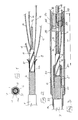
- a slotted core cable for optical fibre ribbons comprises an axial strength member 1, consisting of a cord made of metal, fibre glass or the like, surrounded by a core 2 made of plastics and provided with grooves 3 of helical development adapted to accommodate several superposed optical fibre ribbons 4 (for example five ribbons consisting each of four optical fibres).
- a layer 5 made for example of aramidic fibre or the like, which is pulling-resistant and over which a corrugated sealing (moisture tight) sheath 6 is disposed, made for example of plastics or metal material, which in turn is externally surrounded by a protecting coating 7.
- a cable of the above type is arranged for connection to the drawing head and subsequently to the destination equipment by removing its successive layers in a stepped fashion, so that they may be accessible to the operations necessary for application to the drawing head, which will be described in detail in the following.
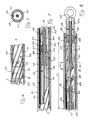
- the drawing head of the invention contiguous portions of which are shown in Figs. 3, 4, 7, 8, comprises a connecting body 8 having an end portion 9 adapted to be fitted over the end portion 1a of the cord 1, a predetermined length of which has been exposed, and fastened to the same for example by plastic deformation of the portion 9 so that the body 8 is made integral with the cord 1; the body 8, as shown in Figs.
- the grooves in the body 8 are of a conveniently increasing depth as they approach the portion 9 so that the path followed by the fibre ribbons from the cable core 2 to the body 8 can extend without substantial local bending increases, that is in an unstepped manner.
- the body 8 also has a threaded hole 11, coaxial with the portion 9 and within which it is engaged the threaded portion 12a of the terminal 12 of a tie rod 13 comprising a metal cable 14 or similar pulling-resistant material to which the terminal 12 is fastened, for example by mechanical deformation.
- the terminal 12 is conveniently locked to the body 8 through a pair of countertightened nuts 15.
- a hollow body 16 made of deformable material, preferably plastic material such as polytetrafluoroethylene (PTFE), having several substantially longitudinal or helical grooves 17 the number, section and pitch of which correspond to those of the body 8 and adapted to receive the optical fibre ribbons 4 housed in said body 8; for the purpose of keeping the alignment between the grooves of body 8 and those of body 18, the latter is provided with an axially projecting dog 18 designed to be received in a corresponding cavity of body 8, as shown in Fig. 6.
- PTFE polytetrafluoroethylene
- grooves 10 and 17 preferably have a helical development on the surfaces of body 8 and body 16 respectively and their pitch corresponds to that of grooves 3 in the cable core 2, or at all events it is such that it does not impose important bending increases to the fibre ribbons accommodated within the grooves and in the transition area from core 2 to body 8.
- the slotted body 16 and tie rod 13 at the inside thereof have a length corresponding to the housing in the slotted body grooves of a portion of fibre ribbons adapted for the cable connecting operations or the like; for example the body 16 can be of a length ranging between 50 cm and one meter so that a corresponding length of fibre ribbons can be available for the necessary connections, once the drawing head has been removed.
- a sleeve 21 made integral with the metal cable 14 for example by plastic deformation of one portion 22 thereof; the sleeve 21 has a thread 23 on which nuts 24, 25 are countertightened; the latter axially lock a dish 26 against which one end of a spring 27 comes in abutment, while the other end of said spring acts on the body 16.
- the opposite portion 33 of the outer sleeve 32 is in turn fitted on the cable protecting coating 7, a sealant 7a being optionally interposed therebetween, whereas the middle portion of the sleeve 32 has a thread for the engagement of a tubular body 34 tightened thereon until its head 35 is brought into abutment against the body 8.
- the above structure enables the cable sheath 6, layer 5 and cord 1 to be integrally pulled so that the pulling loads applied to the cable can be distributed among them depending upon the design features of the cable itself, thereby avoiding the occurrence of relative movements between the parts submitted to a pulling action which could induce stresses in the fibre ribbons 4.
- the body 8 is provided with a radial hole in which a pin 36 is slidably movable the inwardly directed end of which is chamfered and in engagement with a grub screw 37 screwed down in the threaded hole 11.
- the tightening of the grub screw 37 produces the axial outward sliding of the pin 36 so that its end tip 38 is brought into engagement with the tubular body 34, preventing it from rotating relative to the body 8 and in this way offering the assurance that the tubular body 34 will not come unscrewed, which would alter the distribution of pulling loads between the different resistant components of the cable.
- the pin 36 by preventing the support body 8 and tubular body 34 from rotating with respect to each other, enables the tightening of terminal 12 into the threaded hole of the body 8, the rotation of body 8 being directly locked by its catching action on body 34, without deformable elements being interposed which could give rise to slight rotations between the body 8 and the cable, thereby stressing the fibres.
- Each group of fibre ribbons 4 coming out of one of the grooves in the cable core 2 is housed in the corresponding groove 10 in body 8 and then in the groove 17 of body 16, while substantially keeping the same bending value as within the cable; at the end of body 16 the fibre ribbons are cleaved at different gradually-growing lengths starting from the lower ribbon, and a respective connector 39 is applied to each ribbon, as shown in Figs. 7 and 8.
- the ribbons and respective connectors are conveniently accommodated within respective grooves 40 in a tubular support body 41 made of deformable material where the connectors are received and form a respective housing by elastic deformation of the material, being therein protected against impacts, shakings and the like.
- the first one of a series of tubular segments or tube portions 42 which are articulated with respect to one another and coat the body 16 thereby offering a protection against mechanical stresses to the fibre ribbons housed within said body; the last one of said segments is located adjacent the sleeve 21 and a tubular sheath 43 rests thereagainst, said sheath covering the deformable support body 41 and protecting fibre ribbons and connectors at the inside thereof.
- each tubular segment 42 has one end having a spherical-surface portion 42a of radius R, whereas the opposite end has a corresponding conical surface 42b, designed to be brought into contact with the surface 42a of the contiguous tubular segment; surfaces 42a and 42b are then followed by faced annular portions 42c and 42d respectively.
- the tubular sheath 43 at the opposite end from the one in contact with segments 42, exhibits an abutment surface against which a ring 44 rests; the ring is pushed by a spring 45 preloaded by a ring nut 46 screwed on the terminal 28 thread, which ring nut sandwiches the ring 44, sheath 43, tubular segments 42 and tubular body 34.
- the eyebolt 29, screwed on the terminal 28 too, is thrusted in abutment against the ring nut 46, counteracting the untightening thereof.
- the spring 45 and spring 27, mounted under predetermined preload conditions, ensure that the parts of the drawing head in abutment against each other will be kept in contact also in the presence of elastic elongations of the tie rod 13 submitted to a tractive effort, during the laying of the cable for example.
- the hydraulic sealing of the drawing head in accordance with the invention can be ensured by an outer sealing sheath 47, made of elastomeric material, fitted over the cable sheath 7 and elements 34, 42, 43; said sheath can be formed with elastic or heat-shrinkable material or a tape coating or the like.
- the sealing sheath 47 extends as far as it covers one part of the eyebolt 29.
- annular packing 48 located intermediate the ring nut 46 and tubular sheath 43 and a packing 49 located intermediate the eyebolt 29 and ring nut 46.
- seals or similar means can be disposed between each of the outer parts of the drawing head, and they are kept pressed against each other by the spring 45; between the sleeve 32 and the cable coating 7 the sealing can be ensured by a sealant 7a and further sealant can be disposed at the threaded coupling between the sleeve 32 and tubular body 34.
- the cable end is previously prepared stepwise devoid of its layers, so that a cord portion sufficient to fasten the body 8 thereto is made accessible and a core 2 portion corresponding to or greater than the sleeve 30 length is uncovered; the optical fibre ribbons 4 are maintained to the overall length required for the following operations.
- the sleeve 30 and outer sleeve 32 locking the fibre layer 5 therebetween and locking the sleeve 32 on the corrugated cable sheath 6; subsequently the body 8 is fastened to the cord 1, preferably with the aid of a locating apparatus or similar means, enabling the correct alignment between the cable grooves 3 and the grooves 10 of body 8 to be ensured.
- the optical fibre ribbons 3 are therefore led within the grooves 10 and held therein for example by a binding tape 50 or the like; the tubular body 34 is therefore screwed down on the sleeve 32 as far as it comes into abutment against the body 8 and is therefore locked in position by the pin 36 and grub screw 37.
- the tie rod 13 and slotted body 16 previously assembled one within the other and axially slidable with respect to each other, are then mounted, locking the tie rod 13 within the body 8 and aligning the grooves of body 16 and body 8; the fibre ribbons 4 are then located within the respective grooves 17 and optionally held in their housings by a taping or the like, not shown.
- the body 16 is then axially locked on the tie rod 13 through the dish 26 and spring 27.
- the fibre ribbons are finally stepwise cleaved to measure, starting from the innermost one present in each groove and a respective connector is applied thereto; since for the connectors longitudinally fixed housings are not present in the grooves 40, but on the contrary they create proper housings in a self-contained manner within said grooves by elastically deforming the material, a certain number of faults are permissible in applying the connectors.
- the length L of the support body 41 is provided to be in excess relative to the closely necessary length for housing the provided number of connectors without relative interferences, preferably at least by the length of a connector; this, in case of fault, enables one or more repetitions of the application operation of a connector to a ribbon for each group of ribbons housed in a groove; the positions of the ribbon connectors in the various groups are independent of one another.
- the length L is in excess at least by the length of two connectors, so that in case of fault the application of the connectors to the ribbons of each group can be repeated at least twice.
- connector accommodation within housings formed by elastic deformation of the material of the body 41 offers the advantage of elastically fastening the connectors themselves, thereby protecting them against impacts, shakings and the like which can take place during the cable laying step.
- the drawing head can be removed in order to execute the connection of the ribbons through the respective connectors; for the purpose the sealing sheath 47 is moved away for example by tearing it and then the mounting operations are repeated in reverse order, that is the tubular sheath 43, segments 42, body 41, body 16 and tie rod 13 are removed, so that a length of fibre ribbons sufficient to enable the same to reach the respective connection or accommodation points, is made available.
- the connecting body 8, tubular body 34 and sleeve 32 are on the contrary kept fastened to the cable end and can constitute the mechanical fastening members between the cable and the equipment to which the cable must be connected.
- the stress state of an optical fibre or an optical fibre ribbon is connected with the bending (flexion and twisting) thereof; the drawing head in accordance with the invention provides that this stress state in the drawing head itself may be maintained substantially unchanged.
- the change in the diameter on which the helix is wound, the pitch being equal involves a variation in the bending state and in particular the increase in diameter from the cable core 2 to the tubular body 16 involves an increase in the bending while keeping the helix pitch constant.
- the pitch of the slotted body 16 is different from that of the core 2 and in particular, with a diameter of the cavity bottom in body 16 in the range of 2 to 5 times the diameter of the cavity bottom in core 2, the pitch in the body 16 is provided to be of a value in the range of 1.2 to 1.5 times the pitch in the core 2; the body 8 corresponds to a transition area in which the fibres are gradually brought from a helix diameter corresponding to the cable core 2 to a helix diameter corresponding to the slotted body 16 and at the same time the helix pitch changes from the groove pitch in the cable to the groove pitch in the slotted body 16.
- the transition area in its most general formulation can be substantially extended from the end of the sleeve 30 to the end of the connecting body 8 and corresponds to the portion in which the fibre ribbons devoid of outer constraints can be brought to be helically wound on a greater diameter; the transition area, on the other hand, can be of more reduced length should further constraints for the orientation of the fibre ribbons be present.
- a length T (Fig. 3) not lower than 1/7 of the helix pitch in the cable is conveniently provided and preferably a length ranging between 1/5 and 1/2 of the value of said pitch, in connection with diameter values of the cable core and the slotted body in the drawing head as above stated.
- the helix pitch variation from the pitch in the cable core 2 to the pitch intended for the slotted body 16 can be accomplished at least partly in the body 16 itself, by providing a variable pitch for the latter, going from a starting value equal to or slightly higher than the core 2 value until the final maximum value as stated above, optionally in association with a diameter increase of the body 16 itself.
- the structure in accordance with the invention enables therefore the stress state in the fibre ribbons to be held as low as possible, substantially to a value not higher than that present in the cable and in addition enables a complete protection to the fibre ribbons already provided with connectors and to the connectors themselves to be ensured both during the storage and the cable laying, thereby avoiding outer loads being transmitted to the fibre ribbons, for example in case of cable draggings and also preventing water infiltrations towards the ribbons.
- Such a structure at the same time has a diameter which can be compared to the cable diameter, so that it can be led into ducts designed to accommodate the cable with a reduced play without thereby involving greater or too great bendings to the fibre ribbons, the excess length of which, necessary to lead them to the respective connection points, being disposed in a substantially longitudinal direction in the drawing head; the extension in length of the drawing head, on the other hand, does not damage the assembly flexibility necessary for the laying operations, by virtue of the relative articulated feature of the tubular segments 42.
Landscapes
- Physics & Mathematics (AREA)
- General Physics & Mathematics (AREA)
- Optics & Photonics (AREA)
- Engineering & Computer Science (AREA)
- Manufacturing & Machinery (AREA)
- Light Guides In General And Applications Therefor (AREA)
- Cable Accessories (AREA)
- Mechanical Coupling Of Light Guides (AREA)
Applications Claiming Priority (2)
| Application Number | Priority Date | Filing Date | Title |
|---|---|---|---|
| IT1951090 | 1990-02-28 | ||
| IT19510A IT1241067B (it) | 1990-02-28 | 1990-02-28 | Testa di tiro per cavi a fibre a nastro equipaggiati con relativi connettori terminali |
Publications (2)
| Publication Number | Publication Date |
|---|---|
| EP0444572A2 true EP0444572A2 (de) | 1991-09-04 |
| EP0444572A3 EP0444572A3 (en) | 1991-12-04 |
Family
ID=11158647
Family Applications (1)
| Application Number | Title | Priority Date | Filing Date |
|---|---|---|---|
| EP19910102733 Withdrawn EP0444572A3 (en) | 1990-02-28 | 1991-02-25 | Drawing head for ribbon type optical cables equipped with respective end connectors |
Country Status (20)
| Country | Link |
|---|---|
| US (1) | US5129027A (de) |
| EP (1) | EP0444572A3 (de) |
| JP (1) | JPH04216503A (de) |
| KR (1) | KR910021598A (de) |
| CN (1) | CN1027015C (de) |
| AR (1) | AR246619A1 (de) |
| AU (1) | AU640885B2 (de) |
| BR (1) | BR9100898A (de) |
| CA (1) | CA2036969C (de) |
| CZ (1) | CZ282102B6 (de) |
| FI (1) | FI105953B (de) |
| HU (1) | HU214164B (de) |
| IE (1) | IE910546A1 (de) |
| IT (1) | IT1241067B (de) |
| NO (1) | NO180609C (de) |
| NZ (1) | NZ237136A (de) |
| PL (1) | PL163875B1 (de) |
| PT (1) | PT96901B (de) |
| RU (1) | RU2072541C1 (de) |
| SK (1) | SK280421B6 (de) |
Families Citing this family (22)
| Publication number | Priority date | Publication date | Assignee | Title |
|---|---|---|---|---|
| SE515464C2 (sv) * | 1996-07-15 | 2001-08-13 | Telia Ab | Anordning vid kabel |
| US5863083A (en) * | 1996-11-20 | 1999-01-26 | Siecor Corporation | Pulling grip for pre-connectorized fiber optic cable |
| US5938181A (en) * | 1998-04-30 | 1999-08-17 | Strongarm Designs, Inc. | Fish leader for terminated electrical cables |
| US6079134A (en) * | 1998-05-12 | 2000-06-27 | Beshah; Paul T. | Wire loom |
| GB0009164D0 (en) * | 2000-04-14 | 2000-05-31 | B G Intellectual Property Ltd | Pipe threading |
| GB2378212A (en) * | 2001-08-02 | 2003-02-05 | Ibm | Preventing cable damage during installation |
| WO2004002863A2 (en) * | 2002-07-01 | 2004-01-08 | Hazel Danny G | Non-snagging protective guide for fish tapes |
| WO2006021055A1 (en) * | 2004-08-27 | 2006-03-02 | Prysmian Telecom Cables & Systems Australia Pty Ltd | System and device for hauling fibre optic cable along a conduit |
| AU2005276963B2 (en) * | 2004-08-27 | 2010-08-19 | Prysmian Australia Pty Ltd | System and device for hauling fibre optic cable along a conduit |
| WO2006113810A2 (en) * | 2005-04-19 | 2006-10-26 | Adc Telecommunications, Inc. | Fiber breakout with integral connector |
| US8577199B2 (en) * | 2006-09-26 | 2013-11-05 | Prysmian Telecom Cables & Systems Australia Pty Ltd | Hauling shroud for hauling fibre optic cable along a conduit |
| US8800967B2 (en) | 2009-03-23 | 2014-08-12 | Southwire Company, Llc | Integrated systems facilitating wire and cable installations |
| US9802785B2 (en) | 2008-01-21 | 2017-10-31 | Southwire Company, Llc | Systems and methods for facilitating wire and cable installations |
| US10003179B2 (en) | 2008-01-21 | 2018-06-19 | Southwire Company, Llc | Integrated systems facilitating wire and cable installations |
| US8517344B2 (en) * | 2008-03-28 | 2013-08-27 | Daniel Hammons | System and method for installing fiber optic cable |
| US7672562B1 (en) * | 2009-02-27 | 2010-03-02 | Ofs Fitel, Llc | Optical cable having an enlarged section to facilitate pulling |
| EP2773992A1 (de) * | 2011-11-02 | 2014-09-10 | Nanoprecision Products, Inc. | Kastellierte glasfaserkabelhaltestruktur |
| US9537293B2 (en) | 2012-02-29 | 2017-01-03 | Encore Wire Corporation | Wire pulling head apparatus with crimp zone indicators and method of using same |
| RU2551802C2 (ru) * | 2012-12-18 | 2015-05-27 | Владимир Васильевич Гришачев | Устройство защиты оптической сети от несанкционированного зондирования методами оптической рефлектометрии |
| RU2564096C2 (ru) * | 2013-05-22 | 2015-09-27 | Владимир Васильевич Бычков | Специальные соединительные полумуфты |
| CN109824264B (zh) * | 2019-04-15 | 2023-08-18 | 四川省玻纤集团股份有限公司 | 一种玻璃纤维自动换筒拉丝机的推丝结构 |
| CN116661071B (zh) * | 2023-07-20 | 2023-12-01 | 绵阳华岩电子有限公司 | 一种角度可调的圆形连接器 |
Family Cites Families (7)
| Publication number | Priority date | Publication date | Assignee | Title |
|---|---|---|---|---|
| GB1563898A (en) * | 1976-10-19 | 1980-04-02 | Standard Telephones Cables Ltd | Pulling eye for optical cables |
| US4110001A (en) * | 1977-01-05 | 1978-08-29 | General Cable Corporation | Optical fiber cable construction |
| US4337923A (en) * | 1980-09-23 | 1982-07-06 | Smith Jackson A | Fibre optical cable pulling eye |
| DE3512261A1 (de) * | 1985-04-03 | 1986-10-16 | Siemens AG, 1000 Berlin und 8000 München | Optisches kabel mit einer einziehvorrichtung |
| US4691988A (en) * | 1985-11-26 | 1987-09-08 | Tekna Recherche & Developpment Inc. | Pulling eye assembly |
| DE8708258U1 (de) * | 1987-06-11 | 1988-04-07 | Heidelberger Druckmaschinen Ag, 69115 Heidelberg | Schutzvorrichtung für ein Kabelende |
| US5039196A (en) * | 1990-01-22 | 1991-08-13 | Alcatel Na Cable Systems, Inc. | Optical fiber cable pulling eye |
-
1990
- 1990-02-28 IT IT19510A patent/IT1241067B/it active IP Right Grant
-
1991
- 1991-02-11 AU AU70980/91A patent/AU640885B2/en not_active Ceased
- 1991-02-15 NZ NZ237136A patent/NZ237136A/en unknown
- 1991-02-15 AR AR91319065A patent/AR246619A1/es active
- 1991-02-18 IE IE054691A patent/IE910546A1/en unknown
- 1991-02-25 CA CA002036969A patent/CA2036969C/en not_active Expired - Fee Related
- 1991-02-25 EP EP19910102733 patent/EP0444572A3/en not_active Withdrawn
- 1991-02-26 CZ CS91495A patent/CZ282102B6/cs not_active IP Right Cessation
- 1991-02-26 SK SK495-91A patent/SK280421B6/sk unknown
- 1991-02-27 FI FI910971A patent/FI105953B/fi active
- 1991-02-27 RU SU914894757A patent/RU2072541C1/ru active
- 1991-02-27 PT PT96901A patent/PT96901B/pt not_active IP Right Cessation
- 1991-02-27 NO NO910774A patent/NO180609C/no unknown
- 1991-02-27 US US07/661,700 patent/US5129027A/en not_active Expired - Lifetime
- 1991-02-27 PL PL91289222A patent/PL163875B1/pl not_active IP Right Cessation
- 1991-02-28 HU HU91679A patent/HU214164B/hu not_active IP Right Cessation
- 1991-02-28 JP JP3034580A patent/JPH04216503A/ja active Pending
- 1991-02-28 BR BR919100898A patent/BR9100898A/pt not_active IP Right Cessation
- 1991-02-28 KR KR1019910003314A patent/KR910021598A/ko not_active Withdrawn
- 1991-02-28 CN CN91101231A patent/CN1027015C/zh not_active Expired - Fee Related
Also Published As
| Publication number | Publication date |
|---|---|
| CN1055821A (zh) | 1991-10-30 |
| EP0444572A3 (en) | 1991-12-04 |
| AR246619A1 (es) | 1994-08-31 |
| SK280421B6 (sk) | 2000-02-14 |
| BR9100898A (pt) | 1991-11-05 |
| PL289222A1 (en) | 1992-02-24 |
| JPH04216503A (ja) | 1992-08-06 |
| NO180609B (no) | 1997-02-03 |
| NO910774D0 (no) | 1991-02-27 |
| US5129027A (en) | 1992-07-07 |
| CZ282102B6 (cs) | 1997-05-14 |
| PL163875B1 (pl) | 1994-05-31 |
| IT9019510A0 (it) | 1990-02-28 |
| FI910971A0 (fi) | 1991-02-27 |
| CS49591A3 (en) | 1992-01-15 |
| IE910546A1 (en) | 1991-08-28 |
| HU910679D0 (en) | 1991-09-30 |
| PT96901A (pt) | 1993-05-31 |
| HUT60397A (en) | 1992-08-28 |
| IT1241067B (it) | 1993-12-29 |
| AU7098091A (en) | 1991-08-29 |
| IT9019510A1 (it) | 1991-08-28 |
| RU2072541C1 (ru) | 1997-01-27 |
| NO910774L (no) | 1991-08-29 |
| CN1027015C (zh) | 1994-12-14 |
| AU640885B2 (en) | 1993-09-02 |
| HU214164B (hu) | 1998-01-28 |
| KR910021598A (ko) | 1991-12-20 |
| FI910971L (fi) | 1991-08-29 |
| NZ237136A (en) | 1993-12-23 |
| PT96901B (pt) | 1998-08-31 |
| CA2036969C (en) | 1994-12-13 |
| NO180609C (no) | 1997-05-14 |
| FI105953B (fi) | 2000-10-31 |
Similar Documents
| Publication | Publication Date | Title |
|---|---|---|
| EP0444572A2 (de) | Ziehkopf für jeweils mit Endanschlussstücken versehene, bandartige optische Kabel | |
| US4684211A (en) | Fiber optic cable puller | |
| US4697873A (en) | Device for protecting optical fibers freed at the end of a cable element | |
| US5013125A (en) | Pulling eye assembly for connectorized optical fiber cables | |
| US5048918A (en) | Optical fiber cable termination | |
| US8172465B2 (en) | Devices and associated methods for furcating fiber optic cables | |
| US6104855A (en) | Terminal assembly for a multiple fiber optic cable | |
| US5241611A (en) | Cable joint | |
| EP1352271B1 (de) | Glasfaserspleissverstärkung | |
| US7668426B2 (en) | Fiber optic cable assembly with integrated compressing member for strain relief | |
| US7393148B2 (en) | Optical fiber splicing closures and methods | |
| JPS62250404A (ja) | 光フアイバ押し広げ装置 | |
| US4773728A (en) | Method for optical fibre splice protection | |
| US5315682A (en) | Splice device for splicing together under-sea optical cables | |
| CA1299406C (en) | Optical cable connecting section in electric power and optical composite cable | |
| AU664285B2 (en) | Splicing box for submarine cable | |
| EP0449874B1 (de) | Endstück und verbindung für optisches nachrichtentechnikkabel | |
| GB2274175A (en) | Submarine optical cable joint | |
| US12124084B2 (en) | Fiber-optic-splice enclosure | |
| JP2745729B2 (ja) | コネクタ付光ファイバコードの分岐部 | |
| CA2590758C (en) | Tactical flexible fibre optic splice enclosure and method of installation |
Legal Events
| Date | Code | Title | Description |
|---|---|---|---|
| PUAI | Public reference made under article 153(3) epc to a published international application that has entered the european phase |
Free format text: ORIGINAL CODE: 0009012 |
|
| AK | Designated contracting states |
Kind code of ref document: A2 Designated state(s): AT BE CH DE DK ES FR GB LI LU NL SE |
|
| PUAL | Search report despatched |
Free format text: ORIGINAL CODE: 0009013 |
|
| AK | Designated contracting states |
Kind code of ref document: A3 Designated state(s): AT BE CH DE DK ES FR GB LI LU NL SE |
|
| 17P | Request for examination filed |
Effective date: 19920507 |
|
| 17Q | First examination report despatched |
Effective date: 19931112 |
|
| RAP1 | Party data changed (applicant data changed or rights of an application transferred) |
Owner name: PIRELLI CAVI S.P.A. |
|
| STAA | Information on the status of an ep patent application or granted ep patent |
Free format text: STATUS: THE APPLICATION HAS BEEN WITHDRAWN |
|
| 18W | Application withdrawn |
Withdrawal date: 19950216 |