EP0444548A2 - Method and device for applying fastening elements on panels - Google Patents
Method and device for applying fastening elements on panels Download PDFInfo
- Publication number
- EP0444548A2 EP0444548A2 EP91102664A EP91102664A EP0444548A2 EP 0444548 A2 EP0444548 A2 EP 0444548A2 EP 91102664 A EP91102664 A EP 91102664A EP 91102664 A EP91102664 A EP 91102664A EP 0444548 A2 EP0444548 A2 EP 0444548A2
- Authority
- EP
- European Patent Office
- Prior art keywords
- slug
- stamped
- die
- riveted part
- jacket
- Prior art date
- Legal status (The legal status is an assumption and is not a legal conclusion. Google has not performed a legal analysis and makes no representation as to the accuracy of the status listed.)
- Ceased
Links
- 238000000034 method Methods 0.000 title claims abstract description 33
- 238000005520 cutting process Methods 0.000 claims abstract description 28
- 238000004080 punching Methods 0.000 claims description 19
- 238000013459 approach Methods 0.000 claims description 13
- 238000003825 pressing Methods 0.000 claims description 8
- 241000237858 Gastropoda Species 0.000 claims description 4
- 238000005096 rolling process Methods 0.000 claims description 4
- 238000005253 cladding Methods 0.000 claims description 2
- 238000004519 manufacturing process Methods 0.000 abstract description 10
- 239000011159 matrix material Substances 0.000 abstract 2
- 238000007373 indentation Methods 0.000 abstract 1
- 239000002184 metal Substances 0.000 description 19
- 229910000831 Steel Inorganic materials 0.000 description 3
- 239000011248 coating agent Substances 0.000 description 3
- 238000000576 coating method Methods 0.000 description 3
- 238000013461 design Methods 0.000 description 3
- 230000008569 process Effects 0.000 description 3
- 239000010959 steel Substances 0.000 description 3
- 230000003993 interaction Effects 0.000 description 2
- 239000000463 material Substances 0.000 description 2
- 229910000975 Carbon steel Inorganic materials 0.000 description 1
- 238000007605 air drying Methods 0.000 description 1
- 230000015572 biosynthetic process Effects 0.000 description 1
- 238000010276 construction Methods 0.000 description 1
- 238000009826 distribution Methods 0.000 description 1
- 238000001035 drying Methods 0.000 description 1
- NBVXSUQYWXRMNV-UHFFFAOYSA-N fluoromethane Chemical compound FC NBVXSUQYWXRMNV-UHFFFAOYSA-N 0.000 description 1
- 230000001771 impaired effect Effects 0.000 description 1
- 238000005304 joining Methods 0.000 description 1
- 239000000314 lubricant Substances 0.000 description 1
- 230000014759 maintenance of location Effects 0.000 description 1
- 230000007246 mechanism Effects 0.000 description 1
- 238000012986 modification Methods 0.000 description 1
- 230000004048 modification Effects 0.000 description 1
- 238000000465 moulding Methods 0.000 description 1
- 239000004033 plastic Substances 0.000 description 1
- -1 polytetrafluoroethylene Polymers 0.000 description 1
- 229920001343 polytetrafluoroethylene Polymers 0.000 description 1
- 239000004810 polytetrafluoroethylene Substances 0.000 description 1
- 238000012545 processing Methods 0.000 description 1
- 238000000926 separation method Methods 0.000 description 1
- 238000010008 shearing Methods 0.000 description 1
- 229920005992 thermoplastic resin Polymers 0.000 description 1
- 230000007704 transition Effects 0.000 description 1
Images
Classifications
-
- B—PERFORMING OPERATIONS; TRANSPORTING
- B23—MACHINE TOOLS; METAL-WORKING NOT OTHERWISE PROVIDED FOR
- B23P—METAL-WORKING NOT OTHERWISE PROVIDED FOR; COMBINED OPERATIONS; UNIVERSAL MACHINE TOOLS
- B23P19/00—Machines for simply fitting together or separating metal parts or objects, or metal and non-metal parts, whether or not involving some deformation; Tools or devices therefor so far as not provided for in other classes
- B23P19/04—Machines for simply fitting together or separating metal parts or objects, or metal and non-metal parts, whether or not involving some deformation; Tools or devices therefor so far as not provided for in other classes for assembling or disassembling parts
- B23P19/06—Screw or nut setting or loosening machines
- B23P19/062—Pierce nut setting machines
-
- F—MECHANICAL ENGINEERING; LIGHTING; HEATING; WEAPONS; BLASTING
- F16—ENGINEERING ELEMENTS AND UNITS; GENERAL MEASURES FOR PRODUCING AND MAINTAINING EFFECTIVE FUNCTIONING OF MACHINES OR INSTALLATIONS; THERMAL INSULATION IN GENERAL
- F16B—DEVICES FOR FASTENING OR SECURING CONSTRUCTIONAL ELEMENTS OR MACHINE PARTS TOGETHER, e.g. NAILS, BOLTS, CIRCLIPS, CLAMPS, CLIPS OR WEDGES; JOINTS OR JOINTING
- F16B35/00—Screw-bolts; Stay-bolts; Screw-threaded studs; Screws; Set screws
- F16B35/04—Screw-bolts; Stay-bolts; Screw-threaded studs; Screws; Set screws with specially-shaped head or shaft in order to fix the bolt on or in an object
- F16B35/06—Specially-shaped heads
-
- F—MECHANICAL ENGINEERING; LIGHTING; HEATING; WEAPONS; BLASTING
- F16—ENGINEERING ELEMENTS AND UNITS; GENERAL MEASURES FOR PRODUCING AND MAINTAINING EFFECTIVE FUNCTIONING OF MACHINES OR INSTALLATIONS; THERMAL INSULATION IN GENERAL
- F16B—DEVICES FOR FASTENING OR SECURING CONSTRUCTIONAL ELEMENTS OR MACHINE PARTS TOGETHER, e.g. NAILS, BOLTS, CIRCLIPS, CLAMPS, CLIPS OR WEDGES; JOINTS OR JOINTING
- F16B37/00—Nuts or like thread-engaging members
- F16B37/04—Devices for fastening nuts to surfaces, e.g. sheets, plates
- F16B37/06—Devices for fastening nuts to surfaces, e.g. sheets, plates by means of welding or riveting
- F16B37/062—Devices for fastening nuts to surfaces, e.g. sheets, plates by means of welding or riveting by means of riveting
- F16B37/065—Devices for fastening nuts to surfaces, e.g. sheets, plates by means of welding or riveting by means of riveting by deforming the material of the nut
-
- F—MECHANICAL ENGINEERING; LIGHTING; HEATING; WEAPONS; BLASTING
- F16—ENGINEERING ELEMENTS AND UNITS; GENERAL MEASURES FOR PRODUCING AND MAINTAINING EFFECTIVE FUNCTIONING OF MACHINES OR INSTALLATIONS; THERMAL INSULATION IN GENERAL
- F16B—DEVICES FOR FASTENING OR SECURING CONSTRUCTIONAL ELEMENTS OR MACHINE PARTS TOGETHER, e.g. NAILS, BOLTS, CIRCLIPS, CLAMPS, CLIPS OR WEDGES; JOINTS OR JOINTING
- F16B37/00—Nuts or like thread-engaging members
- F16B37/04—Devices for fastening nuts to surfaces, e.g. sheets, plates
- F16B37/06—Devices for fastening nuts to surfaces, e.g. sheets, plates by means of welding or riveting
- F16B37/062—Devices for fastening nuts to surfaces, e.g. sheets, plates by means of welding or riveting by means of riveting
- F16B37/068—Devices for fastening nuts to surfaces, e.g. sheets, plates by means of welding or riveting by means of riveting by deforming the material of the support, e.g. the sheet or plate
-
- Y—GENERAL TAGGING OF NEW TECHNOLOGICAL DEVELOPMENTS; GENERAL TAGGING OF CROSS-SECTIONAL TECHNOLOGIES SPANNING OVER SEVERAL SECTIONS OF THE IPC; TECHNICAL SUBJECTS COVERED BY FORMER USPC CROSS-REFERENCE ART COLLECTIONS [XRACs] AND DIGESTS
- Y10—TECHNICAL SUBJECTS COVERED BY FORMER USPC
- Y10T—TECHNICAL SUBJECTS COVERED BY FORMER US CLASSIFICATION
- Y10T29/00—Metal working
- Y10T29/49—Method of mechanical manufacture
- Y10T29/49826—Assembling or joining
- Y10T29/49833—Punching, piercing or reaming part by surface of second part
- Y10T29/49835—Punching, piercing or reaming part by surface of second part with shaping
- Y10T29/49837—Punching, piercing or reaming part by surface of second part with shaping of first part
-
- Y—GENERAL TAGGING OF NEW TECHNOLOGICAL DEVELOPMENTS; GENERAL TAGGING OF CROSS-SECTIONAL TECHNOLOGIES SPANNING OVER SEVERAL SECTIONS OF THE IPC; TECHNICAL SUBJECTS COVERED BY FORMER USPC CROSS-REFERENCE ART COLLECTIONS [XRACs] AND DIGESTS
- Y10—TECHNICAL SUBJECTS COVERED BY FORMER USPC
- Y10T—TECHNICAL SUBJECTS COVERED BY FORMER US CLASSIFICATION
- Y10T29/00—Metal working
- Y10T29/49—Method of mechanical manufacture
- Y10T29/49826—Assembling or joining
- Y10T29/49908—Joining by deforming
- Y10T29/49915—Overedge assembling of seated part
-
- Y—GENERAL TAGGING OF NEW TECHNOLOGICAL DEVELOPMENTS; GENERAL TAGGING OF CROSS-SECTIONAL TECHNOLOGIES SPANNING OVER SEVERAL SECTIONS OF THE IPC; TECHNICAL SUBJECTS COVERED BY FORMER USPC CROSS-REFERENCE ART COLLECTIONS [XRACs] AND DIGESTS
- Y10—TECHNICAL SUBJECTS COVERED BY FORMER USPC
- Y10T—TECHNICAL SUBJECTS COVERED BY FORMER US CLASSIFICATION
- Y10T29/00—Metal working
- Y10T29/49—Method of mechanical manufacture
- Y10T29/49826—Assembling or joining
- Y10T29/49947—Assembling or joining by applying separate fastener
- Y10T29/49954—Fastener deformed after application
- Y10T29/49956—Riveting
-
- Y—GENERAL TAGGING OF NEW TECHNOLOGICAL DEVELOPMENTS; GENERAL TAGGING OF CROSS-SECTIONAL TECHNOLOGIES SPANNING OVER SEVERAL SECTIONS OF THE IPC; TECHNICAL SUBJECTS COVERED BY FORMER USPC CROSS-REFERENCE ART COLLECTIONS [XRACs] AND DIGESTS
- Y10—TECHNICAL SUBJECTS COVERED BY FORMER USPC
- Y10T—TECHNICAL SUBJECTS COVERED BY FORMER US CLASSIFICATION
- Y10T29/00—Metal working
- Y10T29/53—Means to assemble or disassemble
- Y10T29/5343—Means to drive self-piercing work part
Definitions
- Self-piercing and riveting fasteners such as those shown and described in applicant's U.S. Patent 4,555,838, are used in mass production, including automotive manufacture.
- the fasteners are normally installed by means of a press which develops several tons of compressive force, which can simultaneously deform the sheet material into the desired shape, for example into an automobile body part or stiffening or supporting part, and in the meantime attaches several fasteners to the board.
- One or more punching heads is or are installed in one of the die plates or tool plates of the press, while the opposing counterplate has rivet dies, called dies, for short.
- the fasteners are generally supplied to the punch heads through plastic tubing or slides.
- the punching heads have a conveying mechanism which, in interaction, feeds a fastening element to a plunger or punch in the punching head in order to fasten the respective fastening element to a board located in the press, with each press stroke.
- the self-punching and riveting fasteners of the type described here have a head and a tubular or ring-shaped stamped and riveted part connected to it in one piece.
- a bolt-type fastener of the type described in, for example, the aforementioned U.S. Patent 4,555,838 has a radial collar integrally connected to the stamped and riveted part opposite the free, open end of the stamped and riveted part and a bolt part which in turn is connected to the collar is connected in one piece on the opposite side and extends coaxially to the stamped and riveted part.
- the stamped and riveted part has jacket-like side walls which surround an opening or recess in the stamped and riveted part and a cutting edge adjacent to the open end.
- the opposite end of the stamped and riveted part is closed in the region of the radial web, so that a type of sleeve is formed.
- the die has an annular, concave depression that surrounds a central stamp attachment.
- the central stamp attachment has a free end with a circumferential cutting edge and an outer surface which transitions obliquely into the annular die recess radially outwards.
- a board for example a steel sheet for car bodies or other car components, is attached above the die, preferably in a press described above.
- the punched or riveted part is then driven with its open side into the board in a coaxial orientation to the central stamping attachment of the die.
- the stamp approach is shaped so that it can be received by the opening or recess of the stamped and riveted part. While the stamped and riveted part is pressed into the board, it cuts adjacent to the punching and rivet part recess, a slug from the board, which is received by the free end of the stamping attachment of the die.
- the jacket of the stamped and riveted part is then driven through the opening formed in the sheet into the ring-shaped die depression and is thereby deformed radially in the region of the recess, the punched and riveted part being riveted to the sheet, as described, for example, in the above-mentioned US Pat. Patent 4,555,838.
- a primary aim of this fastening system is to inseparably connect a bolt-like or nut-like fastening element to relatively thin sheet metal, such as is used in the automotive industry, for example, and which can have a thickness of only 0.75 mm or less.
- the tubular stamped and riveted part is deformed radially outward into a U-shaped channel that is open towards the head of the fastening element, while at the same time the sheet metal region surrounding the punched hole is deformed into the center of the U -shaped channel is pressed and deformed such that it completely fills the channel or its center, creating a very secure, mechanical connection between the fastening element and the sheet metal. While the slug is being punched out of the sheet, it gets into the jacket of the punched and riveted part and is finally pressed down to the bottom of the tubular punched and riveted part by the central stamping attachment of the die.
- the slug remains in the stamped and riveted part, in particular in mass production, such as in automobile construction. This is because it is much easier to leave the slug in the connection than to remove it and remove it through the die. In addition, in certain applications it is not possible to remove the slug due to the lack or difficulty of access.
- bolts are attached to auto parts or panels using a press as described. Several bolts can be attached at the same time, and the press preferably runs continuously during a given production run, so that a considerable amount of panel slugs would have to be removed from the area of the press if the slugs were not left in the connection to be created.
- the slug In the cases in which the slug detaches during the attachment of the bolt-like fastening element, it can remain on the central stamp attachment of the die. If a subsequent bolt is then attached to a new sheet, a slug is punched out of this sheet and picked up by the stamping attachment of the die above the first slug. This leads to damage to the punching head or the die, and to deformation of the collar of the second bolt, which can result in the plunger pressing until the collar shears off. It is therefore very important to hold the slug securely in the stamped and riveted part of the bolt-like fastener while it is being attached. The problem of keeping the slug in the stamped and riveted part is particularly difficult when the sheet is relatively thin, as is the case for applications in the automotive industry, where the sheet can be thinner than 1 mm.
- the object of the present invention is to provide a method and a device with which slugs can be securely held in the stamped and riveted part of fastening elements.
- the solution to this problem is based on the surprisingly simple idea of notching or wedging the slug in the stamped and riveted part. It is also achieved with the invention that, without a separate step, the slug is securely held in the stamped and riveted part during the attachment of the fastening element, in that the slug is notched on the sheet metal during the connection of the fastening element.
- the basic idea of the invention thus consists in a method for attaching a self-punching and riveting fastening element, the sheet metal slug being preferably notched or wedged in the stamped and riveted part during attachment.
- the fastening element has an annular stamped and riveted part, the jacket of which surrounds a recess and has a cutting edge adjacent to the recess opening.
- the process steps include moving or pressing the cutting edge against the sheet, punching the slug out of the sheet and forming a hole in the sheet; the side walls or the jacket of the stamped and riveted part are or are then pressed through the hole in the sheet and are preferably shaped radially outward, the punched and riveted part being riveted to the sheet.
- the sheet metal slug is pushed into the recess of the stamped and riveted part and, in the particularly preferred exemplary embodiment, notched against the jacket or the side walls of the stamped and riveted part, whereby the slug is fastened to the stamped and riveted part.
- a plurality of circumferentially distributed notch projections are preferably driven into the slug, as a result of which the slug is pressed against the bottom of the stamped and riveted part and part of the slug is deformed outwards and wedged with the side walls or the jacket.
- the die according to the invention has a plurality of notch projections arranged at a distance from one another on the stamp attachment.
- the die has an annular, concave depression that surrounds a central, protruding punch boss.
- the stamp approach takes on the sheet metal slug with its free end and has an outer cutting edge on it, which is shaped so that it can be received by the recess of the stamped and riveted part.
- the outer surface of the stamp approach radially merges into the die recess to receive the inner surface of the stamped and riveted part.
- the die countersink causes the radially outward deformation of the stamped and riveted part jacket, which is completed in the annular, concave die countersink or rolling surface.
- the free end of its stamp attachment is provided with a plurality of notch projections which are distributed on the circumference with a mutual spacing on the end face of the central stamp attachment.
- Each notch projection preferably consists of a first and a second, bevelled side surface and a head surface.
- the first beveled side surface is preferably next to the punch and rivet shell and is inclined so that it presses a part of the slug against the shell surface when the die insert is driven into the recess of the punch and rivet part.
- the second tapered side surface of each notch protrusion is preferably closest to the center of the free end of the stamp approach.
- the slug edge is deformed outwards by squeezing between the notch projections and the bottom of the stamped and riveted part, as a result of which it attaches itself to the outer surfaces of the stamped and riveted part and is wedged between the outer walls, so that a very secure wedging is formed between the stamped and riveted part and the sheet metal slug, which prevents the slug from falling out unintentionally.
- the self-punching and riveting fastening element described and the die according to the invention are particularly suitable for applications in series production, including automobile production.
- the fastening element 20 shown in the drawings is a preferably threaded bolt according to US Pat. No. 4,555,838, the method and the die according to the invention are not tied to the embodiment of the fastening element shown as an exemplary embodiment. It also means use the term "fastening element” is not restricted to such an element which is designed to attach the sheet metal connected to it to a component by means of a nut or the like.
- the fastening element used in the method according to the invention is provided for permanent connection to a sheet, a board, a plate or the like, preferably with a metal sheet, as is used, for example, in the automotive industry for body parts, claddings and structural parts.
- the fastening element is particularly suitable for use in conventional presses, such as die presses, as are used in the automotive industry for molding metal parts of the type mentioned. In such applications, the press installs one or more fasteners with each stroke, making the fastener a permanent part of the board.
- panel is used in the present context, this term encompasses any type of plate, panel or metal sheet with a thickness which allows the panel to be stamped with the fastening element.
- the fastener can also be used for all applications where rivets are currently used, such as for joining panels and making closures.
- the method according to the invention and the die according to the invention are particularly suitable for holding the sheet metal slug punched out of the sheet by the fastening element in the stamped and riveted part of the fastening element.
- the fastening element 20 in the illustrated embodiment has a stamped and riveted part 22 and a head part with a radial collar or radial flange 24 and a bolt part 26, which is provided with an external thread; however, the bolt may also have a smooth surface or any other shape, including part of a ball joint, or may be used as a nut when formed with an internally threaded recess.
- the stamped and riveted part 22 includes (casing) walls 27 which surround a recess 28.
- the jacket walls 27 have near or at the open end of the recess 28 a chamfered cutting edge or surface 30 and a curved, annular outer surface 32 as a butt and pull edge.
- the truncated-conical cutting surface 30 in combination with the curved abutting and pulling edge 32 provide important advantages for the fastening element.
- the method according to the invention and the die according to the invention are not limited to the described design of the free end of the stamped and riveted part.
- the radial flange 24 passes through the stamped and riveted part and thereby forms a bottom 34 which can be flat (as shown) or concave (not shown). In conjunction with the lateral surfaces 27, the bottom 34 forms an open-ended recess in the manner of a sleeve within the stamped and riveted part 22.
- the radial flange 24 has a radial annular surface 38 - sometimes also referred to as a “pressure surface” - adjacent to the stamped and riveted part 22, and a radial ring surface 40 - also referred to as a "pressing surface” - adjacent to the bolt part 26.
- the punching head includes a plunger 42 which, in the exemplary embodiment shown, has an axial free bore 44 which receives the bolt part 26 of the fastening element.
- the plunger 42 has an annular pressure surface 46 which presses against the pressing surface 40 of the collar 24 of the fastening element.
- a die 50 is typically secured in the opposite tool plate in a coaxial alignment with the ram 42.
- U.S. Patent 4,555,838 describes further suitable embodiments of punch heads suitable for attaching the fasteners described herein. For the description of the present invention, however, it is sufficient to point out that the plunger 42 presses towards the die 50 with sufficient force to fasten the fastening element 20 to the board 76 supported on the die in the manner described below.
- the die 50 has a depression 52 with an annular, concave surface 56 (as a so-called rolling surface) which surrounds a central stamp attachment 58.
- the stamp attachment 58 has a free end 60, on the outer edge of which a circumferential cutting edge 62 is provided.
- the cutting edge 62 is relatively sharp to cooperate with the frusto-conical cutting surface 30 of the punch and rivet 22 to punch the panel.
- other designs of the cutting edge or surface can of course also be used.
- the cutting edge 62 it extends to the Cutting edge 62 then the cutting surface 64 of the plunger projection 58 and tapered radially downwardly widening in the concave annular surface 56 of the Matrizeneinsenkung merges at an angle 66 of approximately 7 o until they.
- the surface of the ring recess 56 is preferably smooth and polished in order to achieve a controlled, radially outward deformation of the stamped and riveted part.
- the die 50 also has an annular die pad 67 which surrounds the depression 52, which in turn has an inwardly inclined shaped slope 68 which receives the board 76 and supports it during its deformation.
- the panel 76 is supported by the die pad 67 during attachment of the fastener 20. It is advisable to clamp the panel to prevent it from moving relative to the die 50.
- the die according to the invention preferably has a plurality of notch projections 80, which extend upwards from the free end 60 of the stamp extension 58.
- Each notch projection has a head surface 82 that intersects a first tapered surface 84 and a second tapered surface 86.
- the first beveled surface 84 is inclined such that it faces (during operation) part of the fastener shell 27 and part of the bottom 34 thereof. The purpose of the preferred inclination of the first beveled surface 84 will be explained in detail later in connection with FIGS. 6 to 9.
- the notch projections 80 preferably have a third side surface 88 and a fourth side surface 90.
- the third and fourth side surfaces 88 and 90 are preferably conically inclined inwards (92) to ensure easy separation from the slug, not shown.
- the notch projections 80 are distributed symmetrically on the free end 60 of the stamp approach near its circumference on the end face. This distribution is preferably provided for a plurality of notch projections in a circle, as shown in FIG. 5. It is important to note that although the notch protrusions 80 are shown in the drawing as separate units, it is also possible within the scope of the invention to realize notch protrusions 80 by means of a single, continuous annular surface which rises from the free end of the stamp approach. A cross section of this annular surface would be identical to that of the individual notch projections shown in FIG. 3.
- the die 50 preferably has a central bore 53 through which any air trapped in the depression 52 during the fastening process can escape.
- FIG. 6 to 8 illustrate the preferred sequence of attaching a self-piercing and riveting fastener and the process of notching the panel slug in the stamped and riveted part according to the invention.
- the jacket 27 is pressed into the panel 76 and thereby pressing the plate 76 against the notch protrusions 80 of the stamp extension 58. Air escapes through the central bore 53 from the depression 52, which would otherwise be enclosed during the fastening process.
- a slug 94 is punched out of the plate 76.
- the slug 94 is in generally take a concave shape because the shear forces act on its edge.
- the portions of the slug 94 that are adjacent to the first tapered surface 84 of the notch protrusions 80 are deformed outwardly as they are compressed between the first tapered surface 84 and the jacket inner surface 96. In this way, a slug 94 is punched out of the sheet in a substantially circular manner in one step.
- the shape of the slug depends on the shape of the stamped and riveted part 22, which need not be circular.
- the stamped and riveted part 22 can be designed to be polygonal, wherein the stamp attachment 58 and the depression 52 would also be designed to be polygonal to accommodate the stamped and riveted part.
- the area 102 of the sheet 76 closest to the punched sheet opening is simultaneously driven into the depression 52 and the slug received by the notch protrusions 80 and the free end 60 of the stamp attachment 58 into the punched and riveted part 22 pushed.
- the diameter of the slug 94 is substantially equal to or slightly larger than the inside diameter of the stamped and riveted part 22.
- the notch projections 80 (during the shearing of the slug 54 from the panel 76) cause the slug 94 to deform slightly, its edge regions closest to the first slanted surface 84 are deformed against the inner surface of the jacket 27.
- Fig. 8 From Fig. 8 it can be seen that while the casing 27 is being driven into the depression 52, its walls oppose the concave ring depression (rolling surface) 56 of the die depression 52 and be deformed radially outwards. Simultaneously with this radial deformation, the notch projections 80 press the slug against the floor 34. As soon as the slug 94 abuts the floor 34, the notch projections 80, slug edge regions 98 begin to squeeze against the floor at point 99, as a result of which they press against the jacket wall 27 in the region of the Inner surface 96 are deformed. Because of their oblique direction, the first beveled surfaces 84 support the direction of deformation of the wall regions 98 against the inner surface 96 of the jacket.
- the radial deformation of the jacket walls 27 leads to the formation of a U-shaped (ring) channel 100, which encompasses the panel area 102, thereby creating a secure, mechanical interlocking of the stamped and riveted part 22 with the panel area 102.
- the invention has been described using the example of a preferred method for attaching a self-punching and riveting fastening element and on the basis of a preferred form of die, various modifications can be made within its scope.
- the dimensions of the fasteners depend on the specific application and the thickness of the board.
- the method according to the invention using the die according to the invention is particularly suitable for the permanent attachment of fastening elements to relatively thin panels, as are used, for example, for bodies and structural parts in the automotive, tool and appliance industries.
- the fastening element described here is preferably made of deformable metal, in particular steel, which can be heat-treated for surface hardening, deformability, etc.
- a suitable material for self-punching and riveting fasteners are typically medium carbon steels, including SAE1022, 1023 and 1030 steels.
- SAE1022, 1023 and 1030 steels are typically medium carbon steels, including SAE1022, 1023 and 1030 steels.
Landscapes
- Engineering & Computer Science (AREA)
- General Engineering & Computer Science (AREA)
- Mechanical Engineering (AREA)
- Insertion Pins And Rivets (AREA)
Abstract
Description
Selbststanzende und nietende Befestigungselemente, wie sie in dem US-Patent 4 555 838 der Anmelderin dargestellt und beschrieben sind, werden in der Massenproduktion einschließlich der Automobilfertigung verwendet. Bei derartigen Anwendungen werden die Befestigungselemente normalerweise mittels einer mehrere Tonnen Druckkraft entwickelnden Presse installiert, die gleichzeitig das Tafelmaterial in die gewünschte Form, beispielsweise zu einem Autokarosserieteil oder Versteifungs- bzw. Tragteil verformen kann, und währenddessen mehrere Befestigungselemente an der Tafel anbringt.Self-piercing and riveting fasteners, such as those shown and described in applicant's U.S. Patent 4,555,838, are used in mass production, including automotive manufacture. In such applications, the fasteners are normally installed by means of a press which develops several tons of compressive force, which can simultaneously deform the sheet material into the desired shape, for example into an automobile body part or stiffening or supporting part, and in the meantime attaches several fasteners to the board.
Ein oder mehrere Stanzköpfe ist bzw. sind in einer der Gesenkplatten bzw. Werkzeugplatten der Presse installiert, während die gegenüberliegende Gegenplatte zu den Stanzköpfen ausgerichtete Nietmatrizen, kurz Matrizen genannt, aufweist. Die Befestigungselemente werden den Stanzköpfen im allgemeinen durch Plastikschläuche oder Rutschen zugeführt. Die Stanzköpfe besitzen einen Fördermechanismus, der jeweils in Wechselwirkung ein Befestigungselement einem Stößel oder Stempel im Stanzkopf zuführt, um das jeweilige Befestigungselement an einer in der Presse befindlichen Tafel zu befestigen, und zwar jeweils mit jedem Pressenhub.One or more punching heads is or are installed in one of the die plates or tool plates of the press, while the opposing counterplate has rivet dies, called dies, for short. The fasteners are generally supplied to the punch heads through plastic tubing or slides. The punching heads have a conveying mechanism which, in interaction, feeds a fastening element to a plunger or punch in the punching head in order to fasten the respective fastening element to a board located in the press, with each press stroke.
Die selbststanzenden und nietenden Befestigungselemente des hier beschriebenen Typs besitzen einen Kopf und ein mit diesem einstückig verbundenes rohr- oder ringförmiges Stanz- und Nietteil. Ein bolzenartiges Befestigungselement der beispielsweise in dem zuvor erwähnten US-Patent 4 555 838 beschriebenen Art besitzt einen radialen, einstückig mit dem Stanz- und Nietteil verbundenen Kragen gegenüber dem freien, offenen Ende des Stanz- und Nietteils und ein Bolzenteil, das seinerseits mit dem Kragen auf dessen gegenüberliegenden Seite einstückig verbunden ist und sich koaxial zum Stanz- und Nietteil erstreckt. Das Stanz- und Nietteil besitzt mantelartige Seitenwände, die eine Öffnung bzw. Ausnehmung im Stanz- und Nietteil umgeben und eine Schneidkante benachbart zum offenen Ende. Das gegenüberliegende Ende des Stanz- und Nietteils ist im Bereich des Radialsteges geschlossen, so daß eine Art Muffe gebildet wird. Die Matrize besitzt eine ringförmige, konkave Einsenkung, die einen zentralen Stempelansatz umgibt. Wie beispielsweise in der erwähnten US-Patentschrift 4 555 838 erläutert, weist der zentrale Stempelansatz ein freies Ende mit einer umlaufenden Schneidkante und eine Außenfläche auf, die radial nach außen schräg in die ringförmige Matrizeneinsenkung übergeht.The self-punching and riveting fasteners of the type described here have a head and a tubular or ring-shaped stamped and riveted part connected to it in one piece. A bolt-type fastener of the type described in, for example, the aforementioned U.S. Patent 4,555,838 has a radial collar integrally connected to the stamped and riveted part opposite the free, open end of the stamped and riveted part and a bolt part which in turn is connected to the collar is connected in one piece on the opposite side and extends coaxially to the stamped and riveted part. The stamped and riveted part has jacket-like side walls which surround an opening or recess in the stamped and riveted part and a cutting edge adjacent to the open end. The opposite end of the stamped and riveted part is closed in the region of the radial web, so that a type of sleeve is formed. The die has an annular, concave depression that surrounds a central stamp attachment. As explained, for example, in the aforementioned US Pat. No. 4,555,838, the central stamp attachment has a free end with a circumferential cutting edge and an outer surface which transitions obliquely into the annular die recess radially outwards.
Eine Tafel, beispielsweise ein Stahlblech für Autokarosserien oder andere Autobauteile wird oberhalb der Matrize, vorzugsweise in einer vorbeschriebenen Presse befestigt. Das Stanz- oder Nietteil wird dann mit seiner offenen Seite in die Tafel in koaxialer Ausrichtung zum zentralen Stempelansatz der Matrize getrieben. Der Stempelansatz ist so geformt, daß er von der Öffnung bzw. Ausnehmung des Stanz- und Nietteils aufgenommen werden kann. Während das Stanz- und Nietteil in die Tafel gedrückt wird, schneidet die benachbart zur Stanz- und Nietteilausnehmung gelegene Schneidkante einen Butzen aus der Tafel, der vom freien Ende des Stempelansatzes der Matrize aufgenommen wird. Der Mantel des Stanz- und Nietteils wird dann durch die in der Tafel gebildete Öffnung in die ringförmige Matrizeneinsenkung getrieben und dabei radial im Bereich der Ausnehmung verformt, wobei das Stanz- und Nietteil mit der Tafel vernietet wird, wie dies zum Beispiel im genannten US-Patent 4 555 838 beschrieben ist.A board, for example a steel sheet for car bodies or other car components, is attached above the die, preferably in a press described above. The punched or riveted part is then driven with its open side into the board in a coaxial orientation to the central stamping attachment of the die. The stamp approach is shaped so that it can be received by the opening or recess of the stamped and riveted part. While the stamped and riveted part is pressed into the board, it cuts adjacent to the punching and rivet part recess, a slug from the board, which is received by the free end of the stamping attachment of the die. The jacket of the stamped and riveted part is then driven through the opening formed in the sheet into the ring-shaped die depression and is thereby deformed radially in the region of the recess, the punched and riveted part being riveted to the sheet, as described, for example, in the above-mentioned US Pat. Patent 4,555,838.
Als die selbststanzenden und nietenden Befestigungselemente der im obengenannten Patent beschriebenen Art erstmals eingeführt wurden, hat es verschiedene Probleme beim Herstellen einer beständigen, hochqualitativen Verbindung gegeben. Ein primäres Ziel dieses Befestigungssystems ist es, ein bolzen- oder mutternartiges Befestigungselement unlösbar mit relativ dünnem Blech, wie es beispielsweise in der Automobilindustrie verwendet wird und das eine Dicke von nur 0,75 mm oder weniger haben kann, zu verbinden. In den besonders bevorzugten Ausführungen der selbststanzenden Befestigungselemente wird das rohrförmige Stanz- und Nietteil in der ringförmigen Matrizeneinsenkung radial nach außen in einen U-förmigen, zum Kopf des Befestigungselements hin offenen Kanal verformt, während gleichzeitig der das gestanzte Loch umgebende Blechbereich in das Zentrum des U-förmigen Kanals gedrückt und derart verformt wird, daß er den Kanal bzw. sein Zentrum völlig ausfüllt, wodurch eine sehr sichere, mechanische Verbindung zwischen dem Befestigungselement und dem Blech geschaffen wird. Während der Butzen aus dem Blech gestanzt wird, gelangt er in den Mantel des Stanz- und Nietteils und wird schließlich bis zu dessen Boden des rohrförmigen Stanz- und Nietteils durch den zentrischen Stempelansatz der Matrize gedrückt.When the self-piercing and riveting fasteners of the type described in the above patent were first introduced, there were various problems in making a durable, high quality connection. A primary aim of this fastening system is to inseparably connect a bolt-like or nut-like fastening element to relatively thin sheet metal, such as is used in the automotive industry, for example, and which can have a thickness of only 0.75 mm or less. In the particularly preferred versions of the self-punching fastening elements, the tubular stamped and riveted part is deformed radially outward into a U-shaped channel that is open towards the head of the fastening element, while at the same time the sheet metal region surrounding the punched hole is deformed into the center of the U -shaped channel is pressed and deformed such that it completely fills the channel or its center, creating a very secure, mechanical connection between the fastening element and the sheet metal. While the slug is being punched out of the sheet, it gets into the jacket of the punched and riveted part and is finally pressed down to the bottom of the tubular punched and riveted part by the central stamping attachment of the die.
Es wurde ursprünglich angenommen, daß der Verbleib des Butzens im Stanz- und Nietteil wichtig dafür sei, ein Zusammenklappen des Stanz- und Nietteils nach innen zu verhindern, während es nach außen radial zu dem vorzugsweise U-förmigen Kanal verformt wird und resultierenden, nach innen gerichteten Kräften ausgesetzt ist, wie dies beispielsweise in dem US-Patent 4 555 838 beschrieben wird. Obwohl der Butzen das Stanz- und Nietteil während der nach außen gerichteten, radialen Verformung abstützt, hat es sich herausgestellt, daß es auch möglich ist, für ein sicheres Anbringen des Befestigungselementes zu sorgen, ohne den Butzen im Stanz- und Nietteil zu halten, und zwar aufgrund nachstehend beschriebener Verbesserungen. Unabhängig davon verbleibt beim bevorzugten Ausführungsbeispiel einer Tafel-Bolzen-Verbindung der Butzen im Stanz- und Nietteil, insbesondere bei der Massenfertigung, wie beispielsweise im Automobilbau. Dies deshalb, weil es wesentlich einfacher ist, den Butzen in der Verbindung zu belassen, als ihn zu entfernen und durch die Matrize abzuführen. Außerdem ist es bei gewissen Anwendungsfällen wegen des Fehlens oder der Schwierigkeit eines entsprechenden Zugangs nicht möglich, den Butzen zu entfernen. Bei einem typischen Anwendungsfall in der Automobilbranche werden Bolzen an Autobauteilen oder Verkleidungen mit Hilfe einer Presse, wie beschrieben, angebracht. Dabei können mehrere Bolzen gleichzeitig angebracht werden, und die Presse läuft vorzugsweise kontinuierlich während eines vorgegebenen Produktionslaufs, so daß eine erhebliche Menge an Tafelbutzen aus dem Bereich der Presse zu entfernen sein würde, wenn die Butzen nicht in der zu erstellenden Verbindung verblieben.It was originally thought that the retention of the slug in the stamped and riveted part was important to prevent the stamped and riveted part from collapsing inward while it was deformed radially outward to the preferably U-shaped channel and resulting inward subjected to directional forces, such as described in U.S. Patent 4,555,838. Although the slug supports the stamped and riveted part during the outward radial deformation, it has been found that it is also possible to ensure a secure attachment of the fastening element without holding the slug in the stamped and riveted part, and due to improvements described below. Regardless of this, in the preferred exemplary embodiment of a panel-bolt connection, the slug remains in the stamped and riveted part, in particular in mass production, such as in automobile construction. This is because it is much easier to leave the slug in the connection than to remove it and remove it through the die. In addition, in certain applications it is not possible to remove the slug due to the lack or difficulty of access. In a typical application in the automotive industry, bolts are attached to auto parts or panels using a press as described. Several bolts can be attached at the same time, and the press preferably runs continuously during a given production run, so that a considerable amount of panel slugs would have to be removed from the area of the press if the slugs were not left in the connection to be created.
Das ursprüngliche Problem beim Herstellen der bevorzugten Ausführung von Verbindungen selbststanzender Befestigungselemente mit einem Blech resultierten aus Toleranzkontrollen und Reibung zwischen der konkaven, ringförmigen Matrizeneinsenkung und dem rohrförmigen Stanz- und Nietteil während der nach außen gerichteten Verformung des Stanz- und Nietteils, wie dies im US-Patent 4 825 525 beschrieben wird, und zwar beträgt die erforderliche Kraft bei einem typischen Anwendungsfall zwischen ungefähr 10 und 20 Tonnen. Besonders bei der Massenherstellung sind die Ausrichtung der Befestigungselemente auf die Matrize und sehr enge Toleranzen kritische Größen, um eine gute und unversehrte Verbindung zu erhalten. Die Montagekraft, die sich aus den für das Stanzen, Verformen des Stanz- und Nietteils und Setzen des Bleches erforderlichen Kräften zusammensetzt, führt zu erheblichen Reibungen zwischen dem Stanz- und Nietteil des Befestigungselements einerseits und der Matrizeneinsenkung andererseits. Der Druck zwischen dem Mantel des Stanz- und Nietteils und der Matrizeneinsenkung kann 8 Tonnen pro cm² übersteigen. Die durch diesen Druck erzeugten Reibungskräfte führten manchmal zum Zusammenklappen des Stanz- und Nietteils oder zum Bruch des Bolzens, zu schlechten oder unfertigen Verbindungen und zu Spannungsrissen oder -fehlern, die die Unversehrtheit der Befestigungsverbindung erheblich reduzierten. Diese Probleme wurden jedoch durch Beschichten zumindest der inneren Oberfläche des Stanz- und Nietteils mit einer reibungsbeständigen Schicht, vorzugsweise einem Fluor-Kohlenstoff-Überzug, wie beispielsweise ein lufttrocknendes Polytetrafluoräthylen-Schmiermittel, suspendiert in einem schnelltrocknenden, thermoplastischen Harz, behoben, wie dies im US-Patent 4 825 525 beschrieben wird.The original problem in making the preferred embodiment of self-piercing fastener connections with a sheet resulted from tolerance controls and friction between the concave, annular die recess and the tubular stamped and riveted part during the outward deformation of the stamped and riveted part, as described in U.S. Patent 4,825,525, which is required Force in a typical application between approximately 10 and 20 tons. Especially in mass production, the alignment of the fasteners on the die and very tight tolerances are critical sizes in order to obtain a good and intact connection. The assembly force, which is composed of the forces required for stamping, deforming the stamped and riveted part and setting the sheet, leads to considerable friction between the stamped and riveted part of the fastening element on the one hand and the die countersink on the other. The pressure between the jacket of the stamped and riveted part and the die countersink can exceed 8 tons per cm². The frictional forces generated by this pressure sometimes led to the collapse of the stamped and riveted part or to the breakage of the bolt, to poor or unfinished connections and to stress cracks or errors which considerably reduced the integrity of the fastening connection. However, these problems have been addressed by coating at least the inner surface of the stamped and riveted part with a friction-resistant layer, preferably a fluorocarbon coating, such as an air-drying polytetrafluoroethylene lubricant suspended in a quick-drying thermoplastic resin, as in the US -
Erhebliche Verbesserungen bei den Herstellungstoleranzen und der Gebrauch eines reibungsbeständigen Überzugs hat zu zuverlässigeren Verbindungen, einschließlich einer ausgezeichneten, mechanischen Verklammerung des Stanz- und Nietteils des Befestigungselements mit dem Blech geführt. Tatsächlich kann bei einigen Anwendungsfällen der Zugwiderstand (gegen Herausreißen) eines typischen bolzenartigen Befestigungselements, wie es in den zuvor erwähnten US-Patenten beschrieben wird, größer sein als die Zugfestigkeit des Bolzens selbst. Diese Verbesserungen haben jedoch ein anderes Problem mit sich gebracht, nämlich die Unmöglichkeit, den Butzen im Stanz- und Nietteil zu halten. Bei Anwendung der zuvor erwähnten Verbesserungen kann der Blechbutzen aus dem Stanz- und Nietteil herausfallen, während die Presse geöffnet wird oder während ein Bauelement an dem mit dem Bolzen versehenen Blech angebracht wird. In den Fällen, in denen sich der Butzen während des Anbringens des bolzenartigen Befestigungselementes löst, kann dieser auf dem zentrischen Stempelansatz der Matrize liegen bleiben. Wenn dann ein nachfolgender Bolzen an einem neuen Blech angebracht wird, wird aus diesem Blech ein Butzen gestanzt und vom Stempelansatz der Matrize über dem ersten Butzen aufgenommen. Dies führt zu Beschädigungen des Stanzkopfes oder der Matrize sowie zu Verformungen des Kragens des zweiten Bolzens, was bis zum Abscheren des Kragens dirch den Preßstempel führen kann. Es ist somit sehr wichtig, den Butzen sicher im Stanz- und Nietteil des bolzenartigen Befestigungselements während dessen Anbringen zu halten. Das Problem des Behaltens des Butzens im Stanz- und Nietteil ist dann besonders schwierig, wenn das Blech relativ dünn ist, wie dies für Anwendungen in der Automobilindustrie zutrifft, wo das Blech dünner als 1 mm sein kann.Significant improvements in manufacturing tolerances and the use of a friction resistant coating have resulted in more reliable connections, including excellent mechanical clamping of the stamped and riveted part of the fastener to the sheet. In fact, in some applications, the tensile (pull-out) resistance of a typical bolt-type fastener, as described in the aforementioned U.S. patents, may be greater than the tensile strength of the bolt itself. However, these improvements have brought about another problem, namely Impossibility of holding the slug in the stamped and riveted part. When applying the aforementioned improvements, the sheet metal slug can fall out of the stamped and riveted part while the press is being opened or while a component is being attached to the sheet metal provided with the bolt. In the cases in which the slug detaches during the attachment of the bolt-like fastening element, it can remain on the central stamp attachment of the die. If a subsequent bolt is then attached to a new sheet, a slug is punched out of this sheet and picked up by the stamping attachment of the die above the first slug. This leads to damage to the punching head or the die, and to deformation of the collar of the second bolt, which can result in the plunger pressing until the collar shears off. It is therefore very important to hold the slug securely in the stamped and riveted part of the bolt-like fastener while it is being attached. The problem of keeping the slug in the stamped and riveted part is particularly difficult when the sheet is relatively thin, as is the case for applications in the automotive industry, where the sheet can be thinner than 1 mm.
Aufgabe der vorliegenden Erfindung ist es, ein Verfahren und eine Vorrichtung zu schaffen, mit denen Butzen gesichert im Stanz- und Nietteil von Befestigungselementen gehalten werden können. Die Lösung dieser Aufgabe basiert auf dem überraschend einfachen Gedanken des Verkerbens bzw. Verkeilens des Butzens im Stanz- und Nietteil. Dabei wird mit der Erfindung auch erreicht, daß ohne einen separaten Schritt der Butzen während des Anbringens des Befestigungselementes sicher im Stanz- und Nietteil gehalten wird, indem der Butzen während des Verbindens des Befestigungselementes am Blech verkerbt wird.The object of the present invention is to provide a method and a device with which slugs can be securely held in the stamped and riveted part of fastening elements. The solution to this problem is based on the surprisingly simple idea of notching or wedging the slug in the stamped and riveted part. It is also achieved with the invention that, without a separate step, the slug is securely held in the stamped and riveted part during the attachment of the fastening element, in that the slug is notched on the sheet metal during the connection of the fastening element.
Der Grundgedanke der Erfindung besteht also in einem Verfahren zum Anbringen eines selbststanzenden und nietenden Befestigungselementes, wobei der Blechbutzen in dem Stanz- und Nietteil vorzugsweise während des Anbringens verkerbt bzw. verkeilt wird. Wie zuvor beschrieben, besitzt das Befestigungselement ein ringförmiges Stanz- und Nietteil, dessen Mantel eine Ausnehmung umgibt und eine Schneidkante benachbart zur Ausnehmungsöffnung besitzt. Zu den Verfahrensschritten gehört das Bewegen bzw. Drücken der Schneidkante gegen das Blech, das Ausstanzen des Butzens aus dem Blech und das Bilden eines Lochs im Blech; die Seitenwände bzw. der Mantel des Stanz- und Nietteils werden bzw. wird dann durch das Loch im Blech gedrückt und vorzugsweise radial nach außen geformt, wobei das Stanz- und Nietteil mit dem Blech vernietet wird. Gleichzeitig wird der Blechbutzen in die Ausnehmung des Stanz- und Nietteils geschoben und beim besonders bevorzugten Ausführungsbeispiel gegen den Mantel bzw. die Seitenwände des Stanz- und Nietteils verkerbt, wodurch der Butzen am Stanz- und Nietteil befestigt wird. Vorzugsweise werden mehrere umfangsmäßig verteilte Kerbvorsprünge in den Butzen getrieben, wodurch der Butzen gegen den Boden des Stanz- und Nietteils gedrückt und ein Teil des Butzens nach außen verformt und mit den Seitenwänden bzw. dem Mantel verkeilt wird.The basic idea of the invention thus consists in a method for attaching a self-punching and riveting fastening element, the sheet metal slug being preferably notched or wedged in the stamped and riveted part during attachment. As described above, the fastening element has an annular stamped and riveted part, the jacket of which surrounds a recess and has a cutting edge adjacent to the recess opening. The process steps include moving or pressing the cutting edge against the sheet, punching the slug out of the sheet and forming a hole in the sheet; the side walls or the jacket of the stamped and riveted part are or are then pressed through the hole in the sheet and are preferably shaped radially outward, the punched and riveted part being riveted to the sheet. At the same time, the sheet metal slug is pushed into the recess of the stamped and riveted part and, in the particularly preferred exemplary embodiment, notched against the jacket or the side walls of the stamped and riveted part, whereby the slug is fastened to the stamped and riveted part. A plurality of circumferentially distributed notch projections are preferably driven into the slug, as a result of which the slug is pressed against the bottom of the stamped and riveted part and part of the slug is deformed outwards and wedged with the side walls or the jacket.
Die erfindungsgemäße Matrize weist mehrere mit Abstand voneinander angeordnete Kerbvorsprünge am Stempelansatz auf. Wie in dem zuvor genannten US-Patent beschrieben wird, besitzt die Matrize eine ringförmige, konkave Einsenkung, die einen zentrischen, vorstehenden Stempelansatz umgibt. Der Stempelansatz nimmt mit seinem freien Ende den Blechbutzen auf und besitzt an diesem eine äußere Schneidkante, die so geformt ist, daß sie von der Ausnehmung des Stanz- und Nietteils aufgenommen werden kann. Die äußere Oberfläche des Stempelansatzes geht radial in die Matrizeneinsenkung über, um die innere Oberfläche des Stanz- und Nietteils aufzunehmen. Die Matrizeneinsenkung bewirkt die radial nach außen gerichtete Verformung des Stanz- und Nietteilmantels, die in der ringförmigen, konkaven Matrizeneinsenkung bzw. Rollfläche fertiggestellt wird.The die according to the invention has a plurality of notch projections arranged at a distance from one another on the stamp attachment. As described in the aforementioned U.S. patent, the die has an annular, concave depression that surrounds a central, protruding punch boss. The stamp approach takes on the sheet metal slug with its free end and has an outer cutting edge on it, which is shaped so that it can be received by the recess of the stamped and riveted part. The outer surface of the stamp approach radially merges into the die recess to receive the inner surface of the stamped and riveted part. The die countersink causes the radially outward deformation of the stamped and riveted part jacket, which is completed in the annular, concave die countersink or rolling surface.
Bei einem bevorzugten Ausführungsbeispiel der Matrize ist das freie Ende ihres Stempelansatzes mit mehreren Kerbvorsprüngen versehen, die am Umfang mit gegenseitigem Abstand auf der Stirnseite des zentrischen Stempelansatzes verteilt sind. Vorzugsweise besteht jeder Kerbvorsprung aus einer ersten und einer zweiten, abgeschrägten Seitenfläche und einer Kopffläche. Die erste abgeschrägte Seitenfläche liegt vorzugsweise nächst dem Stanz- und Nietteilmantel und verläuft derart schräg geneigt, daß sie einen Teil des Butzens gegen die Mantelfläche drückt, wenn der Matrizenstempelansatz in die Ausnehmung des Stanz- und Nietteils getrieben wird. Die zweite abgeschrägte Seitenfläche jedes Kerbvorsprungs liegt vorzugsweise nächst dem Zentrum des freien Endes des Stempelansatzes.In a preferred exemplary embodiment of the die, the free end of its stamp attachment is provided with a plurality of notch projections which are distributed on the circumference with a mutual spacing on the end face of the central stamp attachment. Each notch projection preferably consists of a first and a second, bevelled side surface and a head surface. The first beveled side surface is preferably next to the punch and rivet shell and is inclined so that it presses a part of the slug against the shell surface when the die insert is driven into the recess of the punch and rivet part. The second tapered side surface of each notch protrusion is preferably closest to the center of the free end of the stamp approach.
Bei der bevorzugten Ausführung des erfindungsgemäßen Verfahrens wird der Butzenrand nach außen durch Quetschen zwischen den Kerbvorsprüngen und dem Boden des Stanz- und Nietteils verformt, wodurch er sich gegen die Mantelflächen des Stanz- und Nietteils festsetzt und zwischen den Mantelwänden verkeilt wird, so daß eine sehr sichere Verkeilung zwischen dem Stanz- und Nietteil und dem Blechbutzen gebildet wird, die ein unbeabsichtigtes Herausfallen des Butzens verhindert.In the preferred embodiment of the method according to the invention, the slug edge is deformed outwards by squeezing between the notch projections and the bottom of the stamped and riveted part, as a result of which it attaches itself to the outer surfaces of the stamped and riveted part and is wedged between the outer walls, so that a very secure wedging is formed between the stamped and riveted part and the sheet metal slug, which prevents the slug from falling out unintentionally.
Durch das erfindungsgemäße Verfahren und die erfindungsgemäß vorgeschlagene Ausbildung der Matrize wird somit das Problem eines unbeabsichtigten Entfernens des Blechbutzens vermieden, und zwar auch bei Verbindungen von Befestigungselementen an relativ dünnen Blechen. Der Blechbutzen wird dabei automatisch während des Herstellens der Verbindung im Stanz- und Nietteil verkeilt, wodurch das Erfordernis eines gesonderten Verfahrensschrittes entfällt. Das Verkeilen des Butzens im Stanz- und Nietteil wird durch die Matrize bewirkt, ohne daß dadurch nennenswerte Zusatzkosten entstehen und ohne daß die Standfestigkeit der Matrize und/oder die Unversehrtheit der Befestigungselement-Tafel-Verbindung beeinträchtigt werden. Weitere Vorteile und Merkmale der Erfindung werden nachfolgend anhand der Beschreibung bevorzugter Ausführungsbeispiele, die in den beiliegenden Zeichnungen dargestellt sind, näher erläutert. Es zeigen:
- Fig. 1
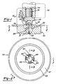
- ein selbststanzendes und nietendes Befestigungselement sowie eine Matrize vor der Montage, in teilweise geschnittener Seitenansicht;
- Fig. 2
- eine Ausführungsform einer erfindungsgemäßen Matrize, in Draufsicht in Richtung der Pfeile 2-2 in Fig. 1;
- Fig. 3
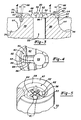
- einen Querschnitt der in Fig. 1 gezeigten Matrize, in Seitenansicht in Richtung der Pfeile 3-3 in Fig. 2;
- Fig. 4
- eine Draufsicht in Richtung der Pfeile 4-4 in Fig. 3;
- Fig. 5
- eine maßgleiche, perspektivische Ansicht der Matrize gemäß Fig. 2;
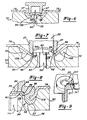
- Fig. 6 bis 8
- die Schrittfolge beim Anbringen des Befestigungselements an einem Blech mit Hilfe der in den Fig. 1 bis 5 gezeigten Matrize, in Querschnitts-Seitenansicht; und
- Fig. 9
- eine perspektivische Darstellung der fertigen Befestigungselement-Tafel-Verbindung, teilweise geschnitten.
- Fig. 1
- a self-piercing and riveting fastener and a die before assembly, in a partially sectioned side view;
- Fig. 2
- an embodiment of a die according to the invention, in plan view in the direction of arrows 2-2 in Fig. 1;
- Fig. 3
- a cross section of the die shown in Figure 1, in side view in the direction of arrows 3-3 in Fig. 2.
- Fig. 4
- a plan view in the direction of arrows 4-4 in Fig. 3;
- Fig. 5
- an isometric, perspective view of the die of FIG. 2;
- 6 to 8
- the sequence of steps in attaching the fastener to a sheet with the aid of the die shown in Figures 1 to 5, in cross-sectional side view. and
- Fig. 9
- a perspective view of the finished fastener-panel connection, partially cut.
Wie zuvor erwähnt, sind das beschriebene selbststanzende und nietende Befestigungselement sowie die erfindungsgemäße Matrize besonders für Anwendungen in der Serienherstellung, einschließlich der Automobilproduktion geeignet. Das in den Zeichnungen dargestellte Befestigungselement 20 ist zwar ein vorzugsweise mit Gewinde versehener Bolzen gemäß dem US-Patent 4 555 838, jedoch sind das erfindungsgemäße Verfahren und die erfindungsgemäße Matrize nicht an die als Ausführungsbeispiel dargestellte Ausbildung des Befestigungselementes gebunden. Außerdem bedeutet die Verwendung des Begriffes "Befestigungselement" keine Beschränkung auf ein solches Element, das zum Anbringen des mit ihm verbundenen Blechs an einem Bauelement mittels einer Mutter od. dgl. ausgebildet ist.As mentioned above, the self-punching and riveting fastening element described and the die according to the invention are particularly suitable for applications in series production, including automobile production. Although the
Das im Rahmen des erfindungsgemäßen Verfahrens verwendete Befestigungselement ist für eine permanente Verbindung mit einem Blech, einer Tafel, einer Platte od. dgl. vorgesehen, vorzugsweise mit einem Metallblech, wie es beispielsweise in der Automobilindustrie für Karosserieteile, Verkleidungen und Konstruktionsteile verwendet wird. Wie in den eingangs erwähnten Patenten beschrieben, eignet sich das Befestigungselement insbesondere für den Einsatz in konventionellen Pressen, wie Gesenkpressen, wie sie in der Automobilindustrie für das Formen von Metallteilen der erwähnten Art verwendet werden. Bei derartigen Anwendungen installiert die Presse ein oder mehrere Befestigungselemente mit jedem Hub, wodurch das Befestigungselement ein permanenter Teil der Tafel wird. Wenn im vorliegenden Zusammenhang von "Tafel" gesprochen wird, so umfaßt dieser Begriff jede Art von Platte, Tafel oder Metallblech mit einer Dicke, die das Stanzen der Tafel mit dem Befestigungselement erlaubt. Das Befestigungselement kann auch für all die Anwendungen vorgesehen werden, bei denen zur Zeit Nieten benutzt werden, wie beispielsweise zum Zusammenfügen von Platten und Herstellen von Verschlüssen. Das erfindungsgemäße Verfahren und die erfindungsgemäße Matrize sind besonders geeignet, den durch das Befestigungselement aus der Tafel gestanzten Blechbutzen im Stanz- und Nietteil des Befestigungselementes festzuhalten.The fastening element used in the method according to the invention is provided for permanent connection to a sheet, a board, a plate or the like, preferably with a metal sheet, as is used, for example, in the automotive industry for body parts, claddings and structural parts. As described in the patents mentioned at the outset, the fastening element is particularly suitable for use in conventional presses, such as die presses, as are used in the automotive industry for molding metal parts of the type mentioned. In such applications, the press installs one or more fasteners with each stroke, making the fastener a permanent part of the board. When the term "panel" is used in the present context, this term encompasses any type of plate, panel or metal sheet with a thickness which allows the panel to be stamped with the fastening element. The fastener can also be used for all applications where rivets are currently used, such as for joining panels and making closures. The method according to the invention and the die according to the invention are particularly suitable for holding the sheet metal slug punched out of the sheet by the fastening element in the stamped and riveted part of the fastening element.
Gemäß Fig. 1 besitzt das Befestigungselement 20 bei der dargestellten Ausführungsform ein Stanz- und Nietteil 22 sowie ein Kopfteil mit einem radialen Kragen oder Radialflansch 24 und einem Bolzenteil 26, der mit einem Außengewinde versehen ist; der Bolzen kann jedoch auch eine glatte Oberfläche oder irgendeine andere Form besitzen, einschließlich Teil eines Kugelgelenks sein oder bei Ausbildung mit einer mit Innengewinde versehenen Ausnehmung als Mutter eingesetzt werden.1, the
Zum Stanz- und Nietteil 22 gehören (Mantel-)wände 27, die eine Ausnehmung 28 umgeben. Die Mantelwände 27 besitzen nahe bzw. am offenen Ende der Ausnehmung 28 eine abgeschrägte Schneidkante bzw. -fläche 30 und eine gewölbte, ringförmige Außenfläche 32 als Stoß- und Ziehkante. Wie in dem eingangs erwähnten US-Patent 4 555 838 beschrieben, ergeben sich durch die kegelstumpf-konische Schneidfläche 30 in Kombination mit der gewölbten Stoß- und Ziehkante 32 wichtige Vorteile für das Befestigungselement. Das erfindungsgemäße Verfahren und die erfindungsgemäße Matrize sind jedoch nicht auf die beschriebene Ausbildung des freien Endes des Stanz- und Nietteils beschränkt. Beim dargestellten Ausführungsbeispiel durchsetzt der Radialflansch 24 das Stanz- und Nietteil und bildet dadurch einen Boden 34, der flach (wie gezeigt) oder konkav (nicht dargestellt) sein kann. In Verbindung mit den Mantelflächen 27 bildet der Boden 34 eine endseitig offene Ausnehmung in Art einer Muffe innerhalb des Stanz- und Nietteils 22. Außerdem weist der Radialflansch 24 eine radiale Ringfläche 38 - gelegentlich auch als "Druckfläche" bezeichnet - benachbart zum Stanz- und Nietteil 22, und eine radiale Ringfläche 40 - auch als "Preßfläche" bezeichnet - benachbart zum Bolzenteil 26 auf.The stamped and riveted
Wenn die Befestigungselemente 20 mit einer Presse angebracht werden, erfolgt dies normalerweise über einen nicht dargestellten Stanzkopf, der mit einer der Pressenplatten verbunden ist. Zum Stanzkopf gehört ein Stößel 42, der im dargestellten Ausführungsbeispiel eine axiale Freibohrung 44 besitzt, die den Bolzenteil 26 des Befestigungselements aufnimmt. Der Stößel 42 besitzt eine Ringdruckfläche 46, die gegen die Preßfläche 40 des Kragens 24 des Befestigungselements drückt. Eine Matrize 50 ist normalerweise in der gegenüberliegenden Werkzeugplatte in koaxialer Ausrichtung zum Stößel 42 befestigt. Das US-Patent 4 555 838 beschreibt weitere geeignete Ausführungsformen von für das Anbringen der hier beschriebenen Befestigungselemente geeigneten Stanzköpfen. Für die Beschreibung der vorliegenden Erfindung ist es jedoch ausreichend, darauf hinzuweisen, daß der Stößel 42 in Richtung auf die Matrize 50 mit hinreichender Kraft drückt, um das Befestigungselement 20 in nachgehend beschriebener Weise an der auf der Matrize abgestützten Tafel 76 zu befestigen.When the
Einzelheiten der erfindungsgemäßen Matrize 50 gehen am besten aus den Fig. 2 bis 5 hervor. Wie dort dargestellt, besitzt die Matrize eine Einsenkung 52 mit einer ringförmigen, konkaven Oberfläche 56 (als sogenannte Rollfläche), die einen zentrischen Stempelansatz 58 umgibt. Der Stempelansatz 58 besitzt ein freies Ende 60, an dessen Außenrand eine umlaufende Schneidkante 62 vorgesehen ist. Wie dargestellt, ist die Schneidkante 62 relativ scharf, um mit der kegelstumpf-konischen Schneidfläche 30 des Stanz- und Nietteils 22 zusammenwirkend die Tafel zu stanzen. Andere Ausbildungen der Schneidkante bzw. -fläche können jedoch selbstverständlich auch zur Anwendung kommen. Beim dargestellten Ausführungsbeispiel verläuft die sich an die Schneidkante 62 anschließende Schneidfläche 64 des Stempelansatzes 58 konisch und radial nach unten sich erweiternd unter einem Winkel 66 von ungefähr 7o, bis sie in die konkave Ringfläche 56 der Matrizeneinsenkung übergeht. Wie für den Fachmann verständlich, ist die Oberfläche der Ringeinsenkung 56 vorzugsweise glatt und poliert, um eine geregelte, radial auswärts gerichtete Verformung des Stanz- und Nietteils zu erreichen. Die Matrize 50 weist außerdem eine ringförmige Matrizenauflage 67 auf, die die Einsenkung 52 umgibt, die ihrerseits eine nach innen geneigte Formschräge 68 besitzt, die die Tafel 76 aufnimmt und während ihrer Verformung abstützt. Die Tafel 76 wird von der Matrizenauflage 67 während des Anbringens des Befestigungselements 20 getragen. Es empfiehlt sich, die Tafel festzuklemmen, um zu vermeiden, daß sie sich relativ zur Matrize 50 bewegt.Details of the die 50 according to the invention can best be seen from FIGS. 2 to 5. As shown there, the die has a
Die erfindungsgemäße Matrize besitzt vorzugsweise mehrere Kerbvorsprünge 80, die sich vom freien Ende 60 des Stempelansatzes 58 aus nach oben erstrecken. Jeder Kerbvorsprung weist eine Kopffläche 82 auf, die eine erste abgeschrägte Fläche 84 und eine zweite abgeschrägte Fläche 86 schneidet. Beim bevorzugten Ausführungsbeispiel ist die erste abgeschrägte Fläche 84 derart geneigt, daß sie (während des Betriebes) teils dem Mantel 27 des Befestigungselements und teils dessen Boden 34 zugewandt ist. Der Zweck der bevorzugten Neigung der ersten abgeschrägten Fläche 84 wird im einzelnen später im Zusammenhang mit den Fig. 6 bis 9 erläutert werden. Die Kerbvorsprünge 80 besitzen vorzugsweise eine dritte Seitenfläche 88 und eine vierte Seitenfläche 90. Die dritte und vierte Seitenfläche 88 bzw. 90 sind vorzugsweise kegelförmig nach innen (92) geneigt, um ein leichtes Trennen vom nicht dargestellten Butzen zu gewährleisten.The die according to the invention preferably has a plurality of
Im bevorzugten Ausführungsbeispiel sind die Kerbvorsprünge 80 symmetrisch auf dem freien Ende 60 des Stempelansatzes nahe seines Umfangs stirnseitig verteilt. Diese Verteilung wird für mehrere Kerbvorsprünge vorzugsweise in einem Kreis vorgesehen, wie dies in Fig. 5 dargestellt ist. Es ist wichtig festzuhalten, daß, obwohl die Kerbvorsprünge 80 in der Zeichnung als gesonderte Einheiten dargestellt sind, es im Rahmen der Erfindung auch möglich ist, Kerbvorsprünge 80 durch eine einzige, durchgehende Ringfläche, die sich vom freien Ende des Stempelansatzes erhebt, zu realisieren. Ein Querschnitt dieser Ringfläche würde identisch mit dem der einzelnen, in Fig. 3 dargestellten Kerbvorsprünge sein. Die Matrize 50 besitzt vorzugsweise eine zentrische Bohrung 53, durch die jegliche Luft, die in der Einsenkung 52 während des Befestigungsvorgangs eingeschlossen wird, entweichen kann.In the preferred embodiment, the
Die Fig. 6 bis 8 stellen die bevorzugte Folge des Anbringens eines selbststanzenden und nietenden Befestigungselements sowie den Vorgang des Verkerbens des Tafelbutzens im Stanz- und Nietteil gemäß der Erfindung dar. Wie aus Fig. 6 hervorgeht, wird der Mantel 27 in die Tafel 76 gedrückt und die Tafel 76 dadurch gegen die Kerbvorsprünge 80 des Stempelansatzes 58 gepreßt. Durch die zentrische Bohrung 53 entweicht Luft aus der Einsenkung 52, die andernfalls während des Befestigungsvorgangs eingeschlossen werden würde.6 to 8 illustrate the preferred sequence of attaching a self-piercing and riveting fastener and the process of notching the panel slug in the stamped and riveted part according to the invention. As shown in FIG. 6, the
Gemäß Fig. 7 wird der Mantel 27 weiter in die Tafel 76 gedrückt und im Zusammenwirken der Schneidkante 62 der Matrize mit der Schneidfläche 30 des Stanz- und Nietteils ein Butzen 94 aus der Tafel 76 gestanzt. Der Butzen 94 wird im allgemeinen eine konkave Form annehmen, da die Scherkräfte auf seinen Rand einwirken. Die Teile des Butzens 94, die sich benachbart zur ersten abgeschrägten Fläche 84 der Kerbvorsprünge 80 befinden, werden nach außen verformt, während sie zwischen der ersten abgeschrägten Fläche 84 und der Mantelinnenfläche 96 zusammengedrückt werden. Auf diese Weise wird ein Butzen 94 aus der Tafel in einem Schritt im wesentlichen kreisförmig ausgestanzt. Es ist jedoch selbstverständlich, daß die Form des Butzens von der Form des Stanz- und Nietteils 22 abhängt, die nicht kreisförmig sein muß. Beispielsweise kann das Stanz- und Nietteil 22 polygonal ausgebildet sein, wobei der Stempelansatz 58 und die Einsenkung 52 ebenfalls polygonal ausgebildet würden, um das Stanz- und Nietteil aufzunehmen.7, the
Während der Mantel 27 in die Einsenkung 52 gedrückt wird, wird der der gestanzten Tafelöffnung nächstliegende Bereich 102 der Tafel 76 gleichzeitig in die Einsenkung 52 getrieben und der von den Kerbvorsprüngen 80 und dem freien Ende 60 des Stempelansatzes 58 aufgenommene Butzen in den Stanz- und Nietteil 22 geschoben. Für den Fachmann ist klar, daß der Durchmesser des Butzens 94 im wesentlichen gleich dem oder etwas größer als der Innendurchmesser des Stanz- und Nietteils 22 ist. Da jedoch die Kerbvorsprünge 80 (während des Abscherens des Butzens 54 von der Tafel 76) eine leichte Deformation des Butzens 94 bewirken, werden dessen nächst der ersten abgeschrägten Fläche 84 liegenden Kantenbereiche gegen die Innenfläche des Mantels 27 verformt.While the
Aus Fig. 8 geht hervor, daß während des Treibens des Mantels 27 in die Einsenkung 52 dessen Wände sich gegen die konkave Ringeinsenkung (Rollfläche) 56 der Matrizeneinsenkung 52 legen und radial nach außen verformt werden. Gleichzeitig mit dieser radialen Verformung drücken die Kerbvorsprünge 80 den Butzen gegen den Boden 34. Sobald der Butzen 94 am Boden 34 anliegt, beginnen die Kerbvorsprünge 80, Butzenrandbereiche 98 gegen den Boden am Punkt 99 zu quetschen, wodurch sie gegen die Mantelwand 27 im Bereich der Mantelinnenfläche 96 verformt werden. Die ersten abgeschrägten Flächen 84 unterstützen aufgrund ihrer Schrägrichtung die Verformungsrichtung der Wandbereiche 98 gegen die Mantelinnenfläche 96. Während die Kerbvorsprünge 80 in den Butzen 94 getrieben werden, schieben die ersten abgeschrägten Flächen 84 nämlich die Butzenrandbereiche 98 gegen die Mantelinnenfläche 96, wodurch der Butzen 94 in festhaltenden Reibsitz innerhalb des Stanz- und Nietteils 22 und gegen den Boden 34 gebracht wird.From Fig. 8 it can be seen that while the
Gemäß Fig. 9 führt die radiale Verformung der Mantelwände 27 zur Bildung eines U-förmigen (Ring-)kanals 100, der den Tafelbereich 102 umfaßt, wodurch eine sichere, mechanische Verhakung des Stanz- und Nietteils 22 mit dem Tafelbereich 102 geschaffen wird.According to FIG. 9, the radial deformation of the
Die vorstehenden Ausführungen zeigen, daß der Butzen 94 innerhalb des Stanz- und Nietteils 22 gleichzeitig mit der Befestigung der Mantelwände 27 am Tafelbereich 102 verkerbt wird.The above statements show that the
Obwohl die Erfindung am Beispiel eines bevorzugten Verfahrens zum Anbringen eines selbststanzenden und nietenden Befestigungselements und anhand einer bevorzugten Matrizenausbildung beschrieben wurde, können in ihrem Rahmen verschiedene Abwandlungen vorgenommen werden. Die Abmessungen der Befestigungselemente hängen von der speziellen Anwendung und der Tafeldicke ab. Wie jedoch zuvor beschrieben wurde, ist das erfindungsgemäße Verfahren unter Verwendung der erfindungsgemäßen Matrize besonders für das dauerhafte Anbringen von Befestigungselementen an relativ dünnen Tafeln geeignet, wie sie beispielsweise für Karosserien und Konstruktionsteile in der Automobil- sowie Werkzeug- und Geräte-Industrie verwendet werden. Das hier beschriebene Befestigungselement wird vorzugsweise aus verformbarem Metall, insbesondere Stahl hergestellt, das bzw. der zur Oberflächenhärtung, Verformbarkeit usw. wärmebehandelt werden kann. Ein geeignetes Material für selbststanzende und nietende Befestigungselemente sind typisch mittelgekohlte Stähle, einschließlich SAE1022, 1023 und 1030-Stähle. Im übrigen wird hinsichtlich weiterer Einzelheiten betreffend geeigneter Verarbeitungsmaschinen, selbststanzender und nietender Befestigungselemente sowie Verfahren zu deren Anbringen auf die einleitend erwähnten US-Patente verwiesen.Although the invention has been described using the example of a preferred method for attaching a self-punching and riveting fastening element and on the basis of a preferred form of die, various modifications can be made within its scope. The dimensions of the fasteners depend on the specific application and the thickness of the board. However, as described above, the method according to the invention using the die according to the invention is particularly suitable for the permanent attachment of fastening elements to relatively thin panels, as are used, for example, for bodies and structural parts in the automotive, tool and appliance industries. The fastening element described here is preferably made of deformable metal, in particular steel, which can be heat-treated for surface hardening, deformability, etc. A suitable material for self-punching and riveting fasteners are typically medium carbon steels, including SAE1022, 1023 and 1030 steels. In addition, for further details regarding suitable processing machines, self-punching and riveting fasteners and methods of attaching them, reference is made to the US patents mentioned at the beginning.
Claims (26)
Applications Claiming Priority (2)
| Application Number | Priority Date | Filing Date | Title |
|---|---|---|---|
| US07/485,340 US5067224A (en) | 1980-02-02 | 1990-02-26 | Method of installing self-attaching fastener and apparatus |
| US485340 | 1990-02-26 |
Publications (2)
| Publication Number | Publication Date |
|---|---|
| EP0444548A2 true EP0444548A2 (en) | 1991-09-04 |
| EP0444548A3 EP0444548A3 (en) | 1993-12-08 |
Family
ID=23927775
Family Applications (1)
| Application Number | Title | Priority Date | Filing Date |
|---|---|---|---|
| EP19910102664 Ceased EP0444548A3 (en) | 1990-02-26 | 1991-02-23 | Method and device for applying fastening elements on panels |
Country Status (3)
| Country | Link |
|---|---|
| US (1) | US5067224A (en) |
| EP (1) | EP0444548A3 (en) |
| CA (1) | CA2022711A1 (en) |
Cited By (3)
| Publication number | Priority date | Publication date | Assignee | Title |
|---|---|---|---|---|
| US5882159A (en) * | 1996-08-16 | 1999-03-16 | Profil Verbindungstechnik, Gmbh & Co. | Element, method of attaching the element to a plate-like component, component assembly and die button |
| WO2015106779A1 (en) * | 2014-01-18 | 2015-07-23 | Audi Ag | Semi-tubular rivet element |
| EP2703734A3 (en) * | 2012-08-28 | 2015-09-16 | BSH Hausgeräte GmbH | Device for a domestic appliance with a base body and a domestic appliance |
Families Citing this family (16)
| Publication number | Priority date | Publication date | Assignee | Title |
|---|---|---|---|---|
| US5140735A (en) * | 1990-01-16 | 1992-08-25 | Multifastener Corporation | Die member for attaching a self-piercing and riveting fastener |
| US5868535A (en) * | 1997-08-04 | 1999-02-09 | Multifastener Corporation | Self-riveting fastening element |
| DE10119505A1 (en) * | 2001-04-20 | 2002-10-24 | Profil Verbindungstechnik Gmbh | Functional part has main body with annular flange leading into cylindrical rivet part and in-between conical surface, sheet metal part and locking part |
| DE10131510A1 (en) * | 2001-07-02 | 2003-04-03 | Newfrey Llc | Fastener and method for its manufacture and use |
| DE10147076A1 (en) * | 2001-09-25 | 2003-04-17 | Profil Verbindungstechnik Gmbh | fastener |
| US7032296B2 (en) * | 2003-11-21 | 2006-04-25 | Newfrey Llc | Self-piercing fastening system |
| US7380326B2 (en) * | 2005-11-02 | 2008-06-03 | Whitesell International Corporation | Method of attaching a self-attaching fastener to a panel |
| PL2359014T3 (en) * | 2008-11-21 | 2016-03-31 | Pem Man Inc | Piercing standoff |
| US8458881B1 (en) | 2011-11-22 | 2013-06-11 | Ford Global Technologies, Llc | Die with multi-sided cavity for self-piercing riveting process |
| EP3280923B1 (en) * | 2015-04-10 | 2020-02-12 | R B & W Manufacturing LLC | Method for installing a self-clinching fastener |
| EP3575618B1 (en) * | 2018-05-30 | 2023-09-13 | Profil Verbindungstechnik GmbH & Co. KG | Self-piercing rivet element, assembly part consisting of the rivet element and a component, method for producing the assembly part and die |
| DE102019113560A1 (en) | 2018-05-30 | 2019-12-05 | Profil Verbindungstechnik Gmbh & Co. Kg | Self-piercing rivet element, assembly part consisting of the rivet element and a component, method for producing the assembly part and die |
| US11209040B2 (en) | 2019-07-15 | 2021-12-28 | Rb&W Manufacturing Llc | Self-clinching fastener |
| CN114402143A (en) * | 2020-06-30 | 2022-04-26 | 株式会社青山制作所 | Pierce nut and method for fixing pierce nut to inner surface of target member having closed cross-sectional shape |
| US11913488B2 (en) | 2021-05-27 | 2024-02-27 | Rb&W Manufacturing Llc | Self-clinching and self-piercing construction element with multi-purpose pilot |
| CN114347139B (en) * | 2022-01-24 | 2024-02-27 | 赣州东印堂包装有限公司 | Semi-automatic die cutting machine with pull gauge auxiliary positioning assembly |
Citations (6)
| Publication number | Priority date | Publication date | Assignee | Title |
|---|---|---|---|---|
| GB2068493A (en) * | 1980-02-02 | 1981-08-12 | Profil Verbindungstechnik Gmbh | Stud bolts |
| US4484385A (en) * | 1982-07-13 | 1984-11-27 | Multifastener Corporation | Method of forming sealed nut and panel assembly |
| US4507859A (en) * | 1982-03-04 | 1985-04-02 | VE-Wissenschaftlich-Technischer Betrieb Keramik | Self-piercing nut holding device |
| DE3404118A1 (en) * | 1984-02-07 | 1985-08-14 | Profil-Verbindungstechnik Gmbh & Co Kg, 6382 Friedrichsdorf | METHOD AND DEVICE FOR ATTACHING A NUT TO A PLATE-SHAPED WORKPIECE |
| US4555838A (en) * | 1983-03-28 | 1985-12-03 | Multifastener Corp. | Method of installing self-attaching fasteners |
| US4825525A (en) * | 1986-08-29 | 1989-05-02 | Obrecht Robert E | Clinching tool |
Family Cites Families (1)
| Publication number | Priority date | Publication date | Assignee | Title |
|---|---|---|---|---|
| US4064617A (en) * | 1976-09-01 | 1977-12-27 | Maclean-Fogg Lock Nut Company | Die assembly and method for clinching fasteners to panels |
-
1990
- 1990-02-26 US US07/485,340 patent/US5067224A/en not_active Expired - Lifetime
- 1990-08-03 CA CA002022711A patent/CA2022711A1/en not_active Abandoned
-
1991
- 1991-02-23 EP EP19910102664 patent/EP0444548A3/en not_active Ceased
Patent Citations (6)
| Publication number | Priority date | Publication date | Assignee | Title |
|---|---|---|---|---|
| GB2068493A (en) * | 1980-02-02 | 1981-08-12 | Profil Verbindungstechnik Gmbh | Stud bolts |
| US4507859A (en) * | 1982-03-04 | 1985-04-02 | VE-Wissenschaftlich-Technischer Betrieb Keramik | Self-piercing nut holding device |
| US4484385A (en) * | 1982-07-13 | 1984-11-27 | Multifastener Corporation | Method of forming sealed nut and panel assembly |
| US4555838A (en) * | 1983-03-28 | 1985-12-03 | Multifastener Corp. | Method of installing self-attaching fasteners |
| DE3404118A1 (en) * | 1984-02-07 | 1985-08-14 | Profil-Verbindungstechnik Gmbh & Co Kg, 6382 Friedrichsdorf | METHOD AND DEVICE FOR ATTACHING A NUT TO A PLATE-SHAPED WORKPIECE |
| US4825525A (en) * | 1986-08-29 | 1989-05-02 | Obrecht Robert E | Clinching tool |
Cited By (4)
| Publication number | Priority date | Publication date | Assignee | Title |
|---|---|---|---|---|
| US5882159A (en) * | 1996-08-16 | 1999-03-16 | Profil Verbindungstechnik, Gmbh & Co. | Element, method of attaching the element to a plate-like component, component assembly and die button |
| EP2703734A3 (en) * | 2012-08-28 | 2015-09-16 | BSH Hausgeräte GmbH | Device for a domestic appliance with a base body and a domestic appliance |
| WO2015106779A1 (en) * | 2014-01-18 | 2015-07-23 | Audi Ag | Semi-tubular rivet element |
| DE102014000623B4 (en) | 2014-01-18 | 2018-09-27 | Audi Ag | Halbhohlnietelement |
Also Published As
| Publication number | Publication date |
|---|---|
| US5067224A (en) | 1991-11-26 |
| CA2022711A1 (en) | 1991-08-27 |
| EP0444548A3 (en) | 1993-12-08 |
Similar Documents
| Publication | Publication Date | Title |
|---|---|---|
| DE3003908C2 (en) | Stud bolts with punching and riveting behavior | |
| DE69216206T2 (en) | Method for attaching a connecting element to a plate and combining a plate and at least one connecting element | |
| DE69101491T2 (en) | Method of attaching a self-piercing rivet element and improved shape. | |
| DE69419890T2 (en) | Device for producing self-punching nuts | |
| DE69507348T2 (en) | Self-locking fastener and method for its manufacture and installation | |
| EP0758039B1 (en) | Anchorage rail for use in construction work | |
| DE3447006C2 (en) | ||
| EP0444548A2 (en) | Method and device for applying fastening elements on panels | |
| DE69230291T2 (en) | METHOD FOR CONNECTING PANELS | |
| DE60207269T2 (en) | Fastening strip and method for its production | |
| DE69630901T2 (en) | METHOD FOR PRESSING IN A CONNECTING ELEMENT, BOLT, RIVETING MATRIX AND COMPONENT ARRANGEMENT | |
| DE69814647T2 (en) | PUNCHED RIVET, PUNCHED RIVET, RIVETING TOOL AND METHOD FOR PRODUCING A RIVETED JOINT | |
| DE3446978A1 (en) | METHOD AND DEVICE FOR ATTACHING A HOLLOW BODY PART TO A PANEL | |
| DE19902461A1 (en) | Nut with T-shaped cross-section for use inside hollow shafts made of e.g. plastic wood | |
| EP2980426A1 (en) | Assembled component comprising a force fitting element and a sheet metal part | |
| DE2353913A1 (en) | SELF-ANCHORING NUT AND PROCEDURE FOR FITTING IT | |
| EP2412991A1 (en) | Self-stamping nut element and assembly component comprising the nut element and a sheet metal section | |
| DE3610675C2 (en) | Method and device for attaching a hollow body to a tabular workpiece | |
| DE10297297B4 (en) | Seat adjustment device, adjustment mechanism, side plate and method for its production | |
| EP3430277A1 (en) | Self-piercing press-in element, press-in connection, and method for producing such a press-in connection | |
| EP0957273B1 (en) | Fastening element and method for manufacturing the same | |
| WO2004055397A1 (en) | Stamped rivet for connection to sheet metals and method for placing said stamped rivet | |
| DE102018117131A1 (en) | Self-punching element and assembly part consisting of the element and a sheet metal part | |
| EP4124765A1 (en) | Punch rivet and method for punch rivetting at least two components | |
| DE69502141T2 (en) | BLIND FASTENING ELEMENT WITH TWO-PIECE SPREADER |
Legal Events
| Date | Code | Title | Description |
|---|---|---|---|
| PUAI | Public reference made under article 153(3) epc to a published international application that has entered the european phase |
Free format text: ORIGINAL CODE: 0009012 |
|
| AK | Designated contracting states |
Kind code of ref document: A2 Designated state(s): DE FR IT |
|
| PUAL | Search report despatched |
Free format text: ORIGINAL CODE: 0009013 |
|
| RHK1 | Main classification (correction) |
Ipc: F16B 37/06 |
|
| AK | Designated contracting states |
Kind code of ref document: A3 Designated state(s): DE FR IT |
|
| 17P | Request for examination filed |
Effective date: 19940118 |
|
| 17Q | First examination report despatched |
Effective date: 19941014 |
|
| GRAG | Despatch of communication of intention to grant |
Free format text: ORIGINAL CODE: EPIDOS AGRA |
|
| STAA | Information on the status of an ep patent application or granted ep patent |
Free format text: STATUS: THE APPLICATION HAS BEEN REFUSED |
|
| 18R | Application refused |
Effective date: 19960712 |