EP0444538B2 - Device and procedure for vacuum evaporation of a material and utilisation of the procedure - Google Patents
Device and procedure for vacuum evaporation of a material and utilisation of the procedure Download PDFInfo
- Publication number
- EP0444538B2 EP0444538B2 EP91102573A EP91102573A EP0444538B2 EP 0444538 B2 EP0444538 B2 EP 0444538B2 EP 91102573 A EP91102573 A EP 91102573A EP 91102573 A EP91102573 A EP 91102573A EP 0444538 B2 EP0444538 B2 EP 0444538B2
- Authority
- EP
- European Patent Office
- Prior art keywords
- arc
- laser
- target
- target surface
- electron beam
- Prior art date
- Legal status (The legal status is an assumption and is not a legal conclusion. Google has not performed a legal analysis and makes no representation as to the accuracy of the status listed.)
- Expired - Lifetime
Links
Images
Classifications
-
- C—CHEMISTRY; METALLURGY
- C23—COATING METALLIC MATERIAL; COATING MATERIAL WITH METALLIC MATERIAL; CHEMICAL SURFACE TREATMENT; DIFFUSION TREATMENT OF METALLIC MATERIAL; COATING BY VACUUM EVAPORATION, BY SPUTTERING, BY ION IMPLANTATION OR BY CHEMICAL VAPOUR DEPOSITION, IN GENERAL; INHIBITING CORROSION OF METALLIC MATERIAL OR INCRUSTATION IN GENERAL
- C23C—COATING METALLIC MATERIAL; COATING MATERIAL WITH METALLIC MATERIAL; SURFACE TREATMENT OF METALLIC MATERIAL BY DIFFUSION INTO THE SURFACE, BY CHEMICAL CONVERSION OR SUBSTITUTION; COATING BY VACUUM EVAPORATION, BY SPUTTERING, BY ION IMPLANTATION OR BY CHEMICAL VAPOUR DEPOSITION, IN GENERAL
- C23C14/00—Coating by vacuum evaporation, by sputtering or by ion implantation of the coating forming material
- C23C14/22—Coating by vacuum evaporation, by sputtering or by ion implantation of the coating forming material characterised by the process of coating
- C23C14/24—Vacuum evaporation
- C23C14/32—Vacuum evaporation by explosion; by evaporation and subsequent ionisation of the vapours, e.g. ion-plating
- C23C14/325—Electric arc evaporation
-
- C—CHEMISTRY; METALLURGY
- C23—COATING METALLIC MATERIAL; COATING MATERIAL WITH METALLIC MATERIAL; CHEMICAL SURFACE TREATMENT; DIFFUSION TREATMENT OF METALLIC MATERIAL; COATING BY VACUUM EVAPORATION, BY SPUTTERING, BY ION IMPLANTATION OR BY CHEMICAL VAPOUR DEPOSITION, IN GENERAL; INHIBITING CORROSION OF METALLIC MATERIAL OR INCRUSTATION IN GENERAL
- C23C—COATING METALLIC MATERIAL; COATING MATERIAL WITH METALLIC MATERIAL; SURFACE TREATMENT OF METALLIC MATERIAL BY DIFFUSION INTO THE SURFACE, BY CHEMICAL CONVERSION OR SUBSTITUTION; COATING BY VACUUM EVAPORATION, BY SPUTTERING, BY ION IMPLANTATION OR BY CHEMICAL VAPOUR DEPOSITION, IN GENERAL
- C23C14/00—Coating by vacuum evaporation, by sputtering or by ion implantation of the coating forming material
- C23C14/22—Coating by vacuum evaporation, by sputtering or by ion implantation of the coating forming material characterised by the process of coating
- C23C14/24—Vacuum evaporation
- C23C14/28—Vacuum evaporation by wave energy or particle radiation
- C23C14/30—Vacuum evaporation by wave energy or particle radiation by electron bombardment
Definitions
- EP-A-O 211 413 describes a ring-shaped ignition device which is arranged around the cathode. There is a small distance between the inner edge of the ignition ring and the target surface, which is used to create the closed one Circuit is connected via a thin film, for example consisting of titanium nitride. At the Ignition process, this thin film is partially evaporated and the ionized material allows it to jump over of the arc from the anode to the cathode. In the subsequent coating process of a substrate, the Film restored.
- the method according to the invention is preferably operated in such a way that the operating power is averaged over time the arc discharge exceeds the operating power of the electron beam or laser, causing evaporation
- the majority of the material on the target surface is carried out by means of the arc discharge.
- the test specimens were used for coating the tools heated the usual method and cleaned its surface in an argon plasma. After that the Electron beam gun switched on and its power increased to 700 watts. The tension between filament and crucible was 10.6 kV. The crucible was rotated at a frequency of 2 revolutions / minute. The Focal spot with a diameter of about 1mm became closer to the exit opening of the electron beam lying sector of the crucible. The pressure in the chamber was less than 0.002 Pa. Then the welding transformer switched on. Its open-circuit voltage of 130 V was sufficient to end a discharge. The current was regulated to 200 A. The operating voltage was 41 V. A circular trench formed in the melt, the bottom of which corresponded to the base of the electron beam.
Abstract
Description
Die vorliegende Erfindung befasst sich mit einer Vorrichtung zum Verdampfen von Material im Vakuum mittels
eines Lichtbogens mit einem Target, das mindestens an einem Teil seiner Oberfläche ein zu verdampfendes Material
aufweist, wobei die Bogenentladung in einem Bereich betrieben wird, wo ein wesentlicher Teil des Bogenstroms meistens
durch kleine Flecken auf der Targetoberfläche fliesst: mit einer Vorrichtung zum Zünden des Verdampfungslichtbogens:
mit einem Verfahren gemäss dem Oberbegriff nach Anspruch 8; mit einem Verfahren zum Zünden des Lichtbogens;
mit einer Plasmalichtbogenanordnung zum Auftragen von Ueberzügen auf ein Substrat mit einer Vorrichtung
sowie mit einer Anwendung des Verfahrens für das Bedampfen von Substraten mittels eines Plasmalichtbogens.The present invention relates to a device for evaporating material in a vacuum
an arc with a target that has at least a portion of its surface a material to be evaporated
has, wherein the arc discharge is operated in an area where a substantial part of the arc current mostly
flows through small spots on the target surface: with a device for igniting the evaporation arc:
with a method according to the preamble of
Verfahren und Anlagen zum Auftragen von Ueberzügen aus relativ hochschmelzenden Materialien durch Niederschlagen des mit Hilfe eines elektrischen Lichtbogens im Vakuum verdampften Materials sind bekannt und in mannigfaltiger Weise vorbeschrieben.Processes and systems for applying coatings from relatively high-melting materials by precipitation of the material vaporized with the help of an electric arc in a vacuum are known and varied Way described above.
Aus der DE-OS 21 36 532 ist eine Anlage bekannt, bei welcher ein elektrischer Lichtbogen zwischen einer hüllenförmigen Anode und einer, auf einem Kühlbett montierten Kathode erzeugt wird, wobei die Kathode an ihrer Oberfläche ein zu verdampfendes Metall enthält. Durch Anbringen eines Schirmes an der Kathode soll verhindert werden, dass der auf der Kathode erzeugte Kathodenfleck von der Verdampfungsfläche seitlich überspringt. Die Problematik dieser Anlage liegt darin, dass infolge des zufälligen ungeführten Wanderns des Kathodenfleckens die Kathodenoberfläche ungleichmässig abgetragen wird und zudem infolge lokaler Ueberhitzung ständig Spritzer entstehen, die zu Störungen auf der zu erzeugenden Beschichtung resp. im Ueberzug führen. Auch die US-PS 36 25 848 beschreibt eine analoge Anlage, wobei hier die Kathode aus dem Beschichtungsmaterial, das zu verdampfen ist, hergestellt ist. Die Anlage weist grundsätzlich dieselben Nachteile auf wie die Anlage gemäss DE-OS 21 36 532.From DE-OS 21 36 532 a system is known in which an electric arc between an envelope-shaped Anode and a cathode mounted on a cooling bed is generated, the cathode on its surface contains a metal to be evaporated. By attaching a screen to the cathode, the aim is to prevent that the cathode spot generated on the cathode jumps over from the evaporation surface. The problem This facility is due to the accidental unguided migration of the cathode spot to the cathode surface is removed unevenly and, in addition, as a result of local overheating, splashes constantly occur, which too Faults on the coating to be produced or lead in the coating. The US-PS 36 25 848 describes an analog system, the cathode being made from the coating material to be evaporated. The system basically has the same disadvantages as the system according to DE-OS 21 36 532.
In der Anlage gemäss US-PS 4 556 471 wird mittels eines Magnetfeldes oder durch Anbringen einem Permanentmagneten versucht, den Lichtbogen so weit in seiner "Wanderung" zu beeinflussen, dass die Kathodenoberfläche oder das sogenannte Target weitgehendst gleichförmig abgetragen wird. Dabei ist die Kathode zusätzlich gegenüber der Vakuumkammer isoliert angeordnet. Grundsätzlich aber wandert der Lichtbogenfleck auf der Kathode weiterhin ungeführt und zufällig, wodurch die beschriebenen Nachteile nur teilweise behoben sind und nach wie vor die Gefahr von Spritzern bestehen bleibt. In der US-PS 4 620 913 wird eine Anlage beschrieben, wo mittels einer speziellen Anodenanordnung das Wegwandern oder das Ueberspringen des Fleckens von der Kathode verhindert werden soll. Auch die DE-OS 35 28 677 bezweckt durch das Anbringen von Lichtbogenbegrenzungsmitteln das Wegspringen des Lichtbogenfleckens, wobei hier zusätzlich durch Anbringen einer Magnetfeldquelle der Fleck eine gelenkte Bewegung auf der Kathode aufweisen soll. Durch gepulste Magnetfelderzeugung wird der Fleck je nach Polarisation veranlasst, sich in Richtung oder gegen das Magnetfeld zu bewegen. Es handelt sich dabei nur um ein "richtungsmässiges", aber nicht um ein eigentliches Führen des Fleckens, so dass - wohl etwas reduziert - immer noch die Gefahr von örtlicher Ueberhitzung und damit von Spritzern nicht vollständig behoben ist. Auch ist es nicht gelungen, Systeme dieser Art zufriedenstellend zu realisieren.The system according to US Pat. No. 4,556,471 uses a magnetic field or by attaching a permanent magnet tries to influence the arc in its "migration" so far that the cathode surface or the so-called target is removed largely uniformly. The cathode is also opposite the Vacuum chamber arranged in isolation. Basically, however, the arc spot continues to move on the cathode without guidance and randomly, whereby the disadvantages described are only partially remedied and the risk of Splashes persists. In US-PS 4 620 913 a system is described where by means of a special anode arrangement the migration or the jumping of the stain from the cathode should be prevented. Also the DE-OS 35 28 677 is intended to cause the arc spot to jump away by attaching arc limiting means, where in addition, by attaching a magnetic field source, the stain directs movement on the Should have cathode. The spot is caused by pulsed magnetic field generation depending on the polarization To move towards or against the magnetic field. It is only a "directional" one, but not to actually guide the stain so that - probably somewhat reduced - there is still the risk of local overheating and is therefore not completely eliminated by splashes. Systems of this type have also failed to realize.
In der DE-OS 33 45 493 wird wiederum das Wegwandern des Fleckens mittels Anordnung eines Begrenzungsringes an der Kathode verhindert, jedoch ohne Beeinflussung der zufälligen Bewegung des Lichtbogenflekkens. Auch in der DE-PS 33 45 442 wird das Anbringen eines Begrenzungsringes aus einem magnetisch permeablen Material beansprucht.In DE-OS 33 45 493 the migration of the stain is in turn by arranging a limiting ring prevented on the cathode, but without influencing the accidental movement of the arc spot. Also in DE-PS 33 45 442 the attachment of a limiting ring made of a magnetically permeable material claimed.
In der DE-PS 31 52 131 wird in der Vakuumkammer ein Magnetfeld durch ein sogenanntes Solenoid erzeugt. Durch dieses Magnetfeld wird der Kathodenstrahlfleck zum Wandern veranlasst. Weiter ist ein Zündimpulsgenerator vorgesehen zum kontinuierlichen Zünden von Kathodenstrahlflecken, die dann infolge des Magnetfeldes zu einer Stirnfläche hinwandern. Der Fleck wird aber nicht eigentlich gesteuert, sondern nur sein Wandern vom Zufallsgenerator entlang der Kathodenoberfläche zur Stirnseite hin veranlasst.In DE-PS 31 52 131 a magnetic field is generated in the vacuum chamber by a so-called solenoid. This magnetic field causes the cathode ray spot to migrate. Next is an ignition pulse generator intended for the continuous ignition of cathode ray spots, which then become a face due to the magnetic field hinwandern. However, the stain is not actually controlled, but only its wandering from the random generator caused along the cathode surface to the front side.
In der CH-PS 657 242 wird beschrieben, wie die entstehenden Spritzer oder Makroteilchen im Plasma ausgeschieden werden. Angeordnet wird ein sogenannter Plasmaleiter und ein koaxial angeordneter Elektromagnet, der zu einem Fokussiersolenoid gegengeschaltet ist. Dadurch wird ein spezielles Magnetfeld erzeugt, das den Plasmastrahl derart umlenkt, dass darin enthaltene Spritzer resp. Makroteilchen aus dem Plasmaleiter ausgetrieben werden. Diese Umlenkung ist aber mit grossen Materialverlusten verbunden. Ausserdem muss der Umlenkmechanismus, der sehr viel stärker beschichtet wird als die Substrate, ständig gereinigt werden, was mit grossem Aufwand und erheblichen Umtrieben verbunden ist. Entsprechendes wird in der FR-A 2 524 254 beansprucht. Die DE-PS 32 34 100 schliesst sich im Prinzip an den Gehalt der beiden vorgenannten Dokumente an, wobei zusätzlich apparative Modifikationen vorgeschlagen werden, um eine gleichmässigere Beschichtung eines Werkstückes zu gewährleisten. Diese beziehen sich aber in keiner Weise auf das Führen des Fleckens auf der Kathodenoberfläche.CH-PS 657 242 describes how the resulting splashes or macro particles are excreted in the plasma become. A so-called plasma conductor and a coaxially arranged electromagnet are arranged is switched against a focusing solenoid. This creates a special magnetic field, which is the plasma beam deflected such that splashes contained therein. Macro particles are driven out of the plasma conductor. This Redirection is associated with large material losses. In addition, the deflection mechanism, which is very is coated much more strongly than the substrates, constantly cleaned, which is very time-consuming and considerable Amusingly connected. The same is claimed in FR-A 2 524 254. DE-PS 32 34 100 closes in principle to the content of the two aforementioned documents, with additional equipment modifications be proposed to ensure a more uniform coating of a workpiece. Get these but does not in any way affect the leading of the stain on the cathode surface.
In der DE-OS 37 31 127 wird ein Lichtbogen gepulst betrieben, d.h. die Substanztemperatur wird mit einer Temperaturobergrenze verglichen, resp. bei Ueberschreiten dieser Obergrenze wird der Lichtbogen unterbrochen. Damit soll ein örtliches Ueberhitzen an der Kathodenoberfläche verhindert werden. Trotzdem entstehende Spritzer sollen mittels Anbringen von Magnetfeld/Abschirmblech abgelenkt werden, d.h., dass das Pulsen nur eine sehr ungenügende Lösung darstellt. Abschirmungen mit Magnetfeld und Blenden sind aber unwirtschaftlich, da sie einen sehr hohen Wartungsaufwand erfordern und die Beschichtungsgeschwindigkeit stark beeinträchtigen. Das beschriebene Verfahren eignet sich insbesondere für dekorative Beschichtungen und weniger für Beschichtungen im technischen Bereich.In DE-OS 37 31 127 an arc is operated in a pulsed manner, i.e. the substance temperature is with an upper temperature limit compared, resp. the arc is interrupted when this upper limit is exceeded. In order to local overheating on the cathode surface should be prevented. Splashes should still occur can be deflected by attaching a magnetic field / shielding plate, i.e. that the pulsing is only a very insufficient one Solution. Shielding with a magnetic field and screens are uneconomical because they are very high Require maintenance and severely affect the coating speed. The procedure described is particularly suitable for decorative coatings and less for technical coatings.
In der US-PS 4 673 477 wird mittels eines Permanentmagneten der Kathodenfleck geführt. Die Anode ist ringförmig ausgebildet und die Kathode verschoben parallel zur Ringfläche als Scheibe ausgebildet. Hinter der Kathode ist ein Magnet angeordnet, mittels welchem der Kathodenfleck auf der Kathodenoberfläche bewegt wird. Obwohl eine Reduktion der Spritzer die Folge dieser Anordnung ist, muss die Konstruktion erneut als kompliziert bezeichnet werden.In US Pat. No. 4,673,477, the cathode spot is guided by means of a permanent magnet. The anode is ring-shaped formed and the cathode shifted parallel to the annular surface formed as a disc. There is a behind the cathode Arranged magnet, by means of which the cathode spot is moved on the cathode surface. Although a reduction If the splash is the result of this arrangement, the construction must again be described as complicated.
Auch in der EP-A 0 284 145 ist die Anode ringförmig und die Kathode parallel versetzt zur Ringebene als Zylinder angeordnet, wobei letzterer um seine Achse rotierbar ist. Um ein wahlloses Wandern des Kathodenfleckes zu verhindern, ist eine Magnetanordnung vorgesehen, die innerhalb des Kathodenzylinders verschiebbar angeordnet ist. Durch Rotation des Zylinders und Längsverschiebung des Magneten wird der Kathodenfleck auf der Oberfläche geführt, um Spritzerbildung zu verhindern. Die vorgeschlagene Anordnung umfasst eine sehr komplizierte Konstruktion, die nicht als sehr praxisgerecht zu bezeichnen ist.Also in EP-A 0 284 145 the anode is ring-shaped and the cathode is offset as a cylinder parallel to the ring plane arranged, the latter being rotatable about its axis. To prevent indiscriminate migration of the cathode spot, a magnet arrangement is provided, which is arranged displaceably within the cathode cylinder. By Rotation of the cylinder and longitudinal displacement of the magnet is guided around the cathode spot on the surface To prevent spattering. The proposed arrangement involves a very complicated construction, which is not can be described as very practical.
In den beiden vorab beschriebenen Fällen hat es sich zudem gezeigt, dass die Spritzerreduktion sehr stark vom Kathodenwerkstoff abhängt, wobei sie für die in der Praxis interessanten Werkstoffe, wie beispielsweise Titan, nicht ausreicht.In the two cases described above, it has also been shown that the spatter reduction is very strong Cathode material depends, but not for the materials of interest in practice, such as titanium sufficient.
In der DE-OS-39 01 401 wird die Verwendung eines zusätzlichen gepulsten Lasers vorgeschlagen, mittels welchem eine Steuerung der Brennfleckbewegung auf der Kathode ermöglicht werden soll, um die Dropletbildung zu minimieren und die Kathodenmaterialausnutzung zu erhöhen. Die Spannung zwischen Anode und Kathode wird pulsierend angelegt und jeweils bei maximaler Spannung ein Laserimpuls, örtlich definiert, auf die Kathodenoberfläche gerichtet. Nach erfolgter zündung beginnt der Kathodenbrennfleck des Lichtbogens unter unmittelbarer Targetverdampfung seinen physikalisch bedingten unkontrollierten Weg über die Targetoberfläche.DE-OS-39 01 401 proposes the use of an additional pulsed laser, by means of which control of the focal spot movement on the cathode is to be made possible in order to prevent droplet formation minimize and increase the cathode material utilization. The voltage between the anode and cathode becomes pulsating and a laser pulse, locally defined, is applied to the cathode surface at maximum voltage directed. After ignition, the cathode focal spot of the arc begins with immediate target evaporation its physically determined uncontrolled path across the target surface.
Die Aufgabe der vorliegenden Erfindung besteht daher nach wie vor in der Forderung nach einem Verfahren resp. einer Anordnung, mittels welcher ein Funken resp. ein Lichtbogenfleck stabilisiert und gesteuert für das Verdampfen eines Beschichtungsmaterials eingesetzt wird, um die Nachteile eines ungesteuerten nichtgeführten Funkens oder Fleckens, wie oben umfangreich dargestellt, zu überwinden. Die Konstruktion und das Verfahren sollen zudem möglichst einfach sein und gegebenenfalls sogar in bestehende Anlagen zugerüstet werden können.The object of the present invention is therefore still the requirement for a method or. an arrangement by means of which a spark or. an arc spot stabilizes and controls for evaporation a coating material is used to the disadvantages of an uncontrolled non-guided spark or Stains, as extensively shown above, to be overcome. The design and procedure should also be as possible be simple and, if necessary, can even be added to existing systems.
Erfindungsgemäss wird dies mittels einer Vorrichtung nach Anspruch 1, sowie mittels eines Verfahrens nach Anspruch
8 gelöst.According to the invention, this is achieved by means of a device according to claim 1 and by means of a method according to
Vorgeschlagen wird eine Vorrichtung zum Verdampfen von Material mittels eines Lichtbogens im Vakuum mit einem Target, das mindestens an einem Teil seiner Oberfläche ein zu verdampfendes Material aufweist, das als Teil einer Bogenentladung geschaltet ist, wobei der Lichtbogen in einem Bereich betrieben wird, wo ein wesentlicher Teil des Bogenstroms meistens durch kleine Flecken auf der Targetoberfläche fliesst, wobei die Vorrichtung zusätzlich eine Elektronenstrahlkanone oder einen kontinuierlich betriebenen Laser beinhaltet, für das Erzeugen einer lokalen Dampfwolke auf der Targetoberfläche, um damit den Fusspunkt des Lichtbogens zu stabilisieren und zu führen, wobei im Falle eines gepulsten Lasers das Zeitintervall zwischen den Pulsen derart zu wählen ist, dass die Bogenentladung kontinuierlich brennt, um ein gleichmässiges und spritzfreies Abtragen der Targetoberfläche zu gewährleisten.A device for evaporating material by means of an arc in a vacuum is also proposed a target that has at least part of its surface a material to be evaporated, the part an arc discharge is switched, the arc being operated in an area where an essential part of the arc current mostly flows through small spots on the target surface, the device additionally having a Includes an electron beam gun or a continuously operated laser for generating a local vapor cloud on the target surface in order to stabilize and guide the base point of the arc, the time interval in the case of a pulsed laser choose between the pulses so that the arc discharge burns continuously to an even and to ensure splash-free removal of the target surface.
Beim Target handelt es sich vorzugsweise um die Kathode des Funkens oder Lichtbogens.The target is preferably the cathode of the spark or arc.
Der Laser oder der Elektronenstrahl ist bevorzugt derart aufgebaut, dass der Elektronenstrahl oder Laserstrahl auf der Targetoberfläche führbar ist. Dabei ist es beispielsweise möglich, die Objektlinse des Lasers beweglich anzuordnen oder weiter einen Spiegel vorzusehen, der für das Wandern des Brennfleckens bewegbar angeordnet ist. Gleichzeitig mit dem Führen von Elektronenstrahl oder Laserstrahl wird damit auch der Lichtbogenfleck auf der Kathodenoberfläche geführt, indem er der durch den Elektronenstrahl oder Laserstrahl erzeugten lokalen Dampfwolke auf der Targetoberfläche nachfolgt. Es ist auch möglich, das Target beweglich anzuordnen.The laser or the electron beam is preferably constructed such that the electron beam or laser beam is feasible on the target surface. It is possible, for example, to arrange the object lens of the laser to be movable or further to provide a mirror which is movably arranged for the migration of the focal spot. Simultaneously with the guiding of the electron beam or laser beam, the arc spot on the cathode surface also becomes led by the local vapor cloud generated by the electron beam or laser beam follows on the target surface. It is also possible to arrange the target movably.
Ein weiteres grosses Problem, welches all den verschiedenen, zum Stande der Technik angeführten Vakuumverdampfungsanlagen resp. Verfahren gemeinsam ist, ist das Zünden eines Funkens resp. Lichtbogens. In der DE-OS 34 13 728 wird hierzu beispielsweise vorgeschlagen, dass der Lichtbogen dadurch gezündet wird, dass eine Kontaktstange oder ein Bogenzündstab, die einerseits auf der Kathodenoberfläche aufliegen und andererseits mit der Stromquelle für die Lichtbogenerzeugung verbunden sind, von der Kathodenoberfläche wegbewegt werden. Bei Eingriff des Zündstabes mit der Kathodenoberfläche besteht ein geschlossener Stromkreispfad. Bei Wegbewegen des Zündstabes springt ein Lichtbogen vom Draht auf die Kathode. Dieser Lichtbogen springt aber sofort auf die Anode über und ist somit gezündet. Die in dieser DE-OS 34 13 728 beschriebene, pneumatisch gesteuerte Konstruktion zum Führen eines Bogenzünddrahtes zur und von der Kathodenoberfläche ist kompliziert und offensichtlich sehr störungsanfällig.Another big problem, which all the different vacuum evaporation plants mentioned to the state of the art respectively. Procedure is common, is the ignition of a spark resp. Arc. In the DE-OS For example, 34 13 728 proposes that the arc be ignited by a contact rod or an arc ignition rod, which on the one hand rests on the cathode surface and on the other hand with the power source connected for arc generation, are moved away from the cathode surface. When the Ignition stick with the cathode surface there is a closed circuit path. When the ignition rod moves away an arc jumps from the wire onto the cathode. However, this arc immediately jumps to the anode and is thus ignited. The pneumatically controlled construction described in this DE-OS 34 13 728 for guiding a Arch wire to and from the cathode surface is complicated and obviously very prone to failure.
Die EP-A- O 211 413 beschreibt eine ringförmige Zündvorrichtung, die um die Kathode herum angeordnet ist. Zwischen Zündringinnenkante und Targetoberfläche besteht ein kleiner Abstand, welcher für das Erzeugen des geschlossenen Stromkreises über einen dünnen Film, beispielsweise bestehend aus Titannitrid, verbunden ist. Beim Zündvorgang wird dieser dünne Film teilweise verdampft und das so ionisierte Material ermöglicht das Ueberspringen des Bogens von der Anode auf die Kathode. Beim anschliessenden Beschichtungsvorgang eines Substrates wird der Film wieder hergestellt.EP-A-O 211 413 describes a ring-shaped ignition device which is arranged around the cathode. There is a small distance between the inner edge of the ignition ring and the target surface, which is used to create the closed one Circuit is connected via a thin film, for example consisting of titanium nitride. At the Ignition process, this thin film is partially evaporated and the ionized material allows it to jump over of the arc from the anode to the cathode. In the subsequent coating process of a substrate, the Film restored.
Auch diese Konstruktion muss als kompliziert bezeichnet werden, und ist insbesondere aufgrund des ständigen Verdampfungs- und Wiederablagerungsprozesses des dünnen Filmes ebenfalls sehr störungsanfällig.This construction must also be described as complicated, and is particularly due to the constant Evaporation and redeposition process of the thin film is also very prone to failure.
In der DE-OS 35 16 598 wird der Lichtbogen mechanisch gezündet, unter Verwendung eines Hebels, der in einem Faltenbalg gelagert ist. Die Konstruktion, welche an diejenige in der DE-OS 34 13 728 erinnert, ist ebenfalls kompliziert und störungsanfällig.In DE-OS 35 16 598 the arc is ignited mechanically, using a lever which in one Bellows is mounted. The construction, which is reminiscent of that in DE-OS 34 13 728, is also complicated and prone to failure.
In der US-PS 4 612 477 erfolgt das Zünden des Lichtbogens elektrisch, unter Verwendung einer sog. Triggerelektrode, welche mit einer Funkenüberbrückungsschaltung derart verbunden ist, dass ein Durchschlagen zwischen Triggerelektrode und der Kathode in vorgegebenen Zeitintervallen stattfindet. Dieser jeweilige Spannungsunterbruch führt zur Zündung des Lichtbogens zwischen der Kathode und der Anode. Insbesondere die Ausgestaltung der Schaltung ist äusserst kompliziert.In US Pat. No. 4,612,477, the arc is ignited electrically, using a so-called trigger electrode, which is connected to a spark bridging circuit in such a way that a breakdown between the trigger electrode and the cathode takes place at predetermined time intervals. This respective voltage interruption leads to ignite the arc between the cathode and the anode. In particular the design of the circuit is extremely complicated.
Analog dazu erfolgt die Zündung des Funkens in der US-PS 4 673 477 durch eine Hochspannungszündeinheit ebenfalls elektrisch. Auch diese Anordnung ist kompliziert und weiter treten oft Schwierigkeiten bei der Trennung zwischen den beiden Entladungen auf.Analogously to this, the spark is ignited in US Pat. No. 4,673,477 by a high-voltage ignition unit also electric. This arrangement is also complicated and further difficulties often arise in the separation between the two discharges.
Es ist daher vorteilhaft, eine Vorrichtung resp. eine Methode vorzuschlagen, gemäss welchen das Zünden eines Funkens resp. Lichtbogens auf einfache und auf möglichst störungsfreie Art und Weise erfolgt.It is therefore advantageous to have a device. propose a method according to which the ignition of a Spark resp. Arc is carried out in a simple and as trouble-free manner as possible.
Dies wird mittels einer Vorrichtung nach Anspruch 5 gelöst.This is achieved by means of a device according to
Vorgeschlagen wird, dass die vorab beschriebene erfindungsgemässe Vorrichtung zum Zünden eines Funkens resp. des Verdampfungslichtbogens mittels der konventionellen Elektronenstrahl-Verdampferquelle resp. mittels eines geeigneten Laserstrahles verwendet wird. Dabei wird durch den Elektronen- resp. Laserstrahl die Oberfläche des Targets, welches als eine Elektrode einer Funkenquelle geschaltet ist, lokal oder über die ganze Fläche aufgeschmolzen resp. über einem kleinen Bereich der Targetoberfläche eine lokale Dampfwolke gebildet und durch Stossionisation des verdampfenden Materials mit den Elektronen des Elektronen- oder Laserstrahls eine partielle lonisierung des Dampfes erreicht. Diese ist ausreichend zur Zündung des Funkens durch Anlegen der Leerlaufspannung zwischen den beiden Elektronen des Funkens resp. Lichtbogens.It is proposed that the device according to the invention for igniting a spark described above respectively. the evaporation arc by means of the conventional electron beam evaporator source, respectively. by means of a suitable laser beam is used. The electron or. Laser beam the surface of the Targets, which is connected as an electrode of a spark source, melted locally or over the entire surface respectively. A local vapor cloud is formed over a small area of the target surface and by impact ionization of the evaporating material with the electrons of the electron or laser beam a partial ionization of the Steam reached. This is sufficient to ignite the spark by applying the open circuit voltage between the two electrons of the spark resp. Arc.
Weitere vorteilhafte Merkmale sind in den Ansprüchen 6 und 7 angeführt.Further advantageous features are set out in
Im weiteren wird ein Verfahren zum Verdampfen eines Materials mittels eines Lichtbogens an einem Target im Vakuum vorgeschlagen, wobei das Target mindestens an seiner Oberfläche ein zu verdampfendes Material aufweist, das als Teil einer Bogenentladung geschaltet ist und wobei die Bogenentladung in einem Bereich betrieben wird, wo ein wesentlicher Teil des Bogenstroms mindestens durch kleine Flecken auf der Targetoberfläche fliesst, indem mittels eines Elektronenstrahls oder eines kontinuierlich betriebenen Lasers auf der Targetoberfläche eine lokale Dampfwolke erzeugt wird, und zwar derart, dass der Fusspunkt des Lichtbogens oder Funkens in dieser Dampfwolke stabilisiert und mit dieser geführt wird wobei im Falle eines gepulsten Lasers das Zeitintervall zwischen den Pulsen derart zu wählen ist, dass die Bogenentladung kontinuierlich brennt, um ein gleichmässiges und spritzfreies Abtragen der Targetoberfläche zu gewährleisten. Dabei ist es zusätzlich möglich, unter der Dampfwolke auf der Targetoberfläche eine Pfütze zu erzeugen.Furthermore, a method for evaporating a material by means of an arc on a target in the Vacuum proposed, the target having at least on its surface a material to be evaporated, which is connected as part of an arc discharge and wherein the arc discharge is operated in an area where a substantial part of the arc current flows at least through small spots on the target surface by using an electron beam or a continuously operated laser on the target surface a local vapor cloud is generated in such a way that the base point of the arc or spark stabilizes in this vapor cloud and is performed with this, in the case of a pulsed laser, the time interval choose between the pulses so that the arc discharge burns continuously to an even and to ensure splash-free removal of the target surface. It is also possible to place a puddle under the vapor cloud on the target surface to create.
Der Elektronenstrahl oder der Laserstrahl sind bevorzugt auf der Targetoberfläche führbar, um so den Lichtbogen resp. Funkenfusspunkt auf der Targetoberfläche zu führen. Die Führung des Elektronenstrahles oder Laserstrahles kann selbstverständlich nach einem vorgegebenen Muster erfolgen, gemäss welchem ein gleichmässiges Abtragen der Targetoberfläche durch den geführten Lichtbogen resp. Funkenfleck gewährleistet ist.The electron beam or the laser beam can preferably be guided on the target surface, in order to avoid the arc respectively. To lead spark base on the target surface. The guidance of the electron beam or laser beam can of course be done according to a predetermined pattern, according to which a uniform removal the target surface by the guided arc, respectively. Spark spot is guaranteed.
Das erfindungsgemässe Verfahren wird bevorzugt derart betrieben, dass im zeitlichen Mittel die Betriebsleistung der Bogenentladung die Betriebsleistung des Elektronenstrahls oder des Lasers übersteigt, wodurch die Verdampfung des Materials an der Targetoberfläche mehrheitlich mittels der Bogenentladung erfolgt.The method according to the invention is preferably operated in such a way that the operating power is averaged over time the arc discharge exceeds the operating power of the electron beam or laser, causing evaporation The majority of the material on the target surface is carried out by means of the arc discharge.
Die Energiedichte des Elektronenstrahles oder Laserstrahles ist insbesondere derart geregelt, dass ein Entladungsstrom von mehr als 30 Ampère bei einer Entladungsspannung von lediglich 10 bis 15 Volt ermöglicht wird.The energy density of the electron beam or laser beam is regulated in particular in such a way that a discharge current of more than 30 amperes with a discharge voltage of only 10 to 15 volts.
Weiter wird vorgeschlagen, dass der über dem Target liegende Verdampfungsraum eine verdünnte Atmosphäre aus Edelgas, Sauerstoff, Stickstoff, einer gasförmigen Kohlenstoffverbindung, einer metallorganischen gasförmigen oder borhaltigen gasförmigen Verbindung aufrechterhalten wird.It is further proposed that the evaporation space above the target be a dilute atmosphere from noble gas, oxygen, nitrogen, a gaseous carbon compound, an organometallic gaseous or gaseous compound containing boron is maintained.
Falls die Targetoberfläche ein leicht schmelzendes Material umfasst, so wird vorzugsweise der Elektronenstrahl oder Laserstrahl so stark defokussiert, dass die Pfütze um den Lichtbogenfusspunkt der Bogenentladung ständig einen Trichter bildet, in dessen Grund immer flüssiges Targetmaterial nachrinnt, wodurch der Lichtbogen stabilisiert wird, ohne Führung.If the target surface comprises a readily melting material, the electron beam is preferably used or laser beam so strongly defocused that the puddle around the arc base of the arc discharge is constantly one Forms a funnel, in the bottom of which liquid target material always runs, stabilizing the arc, without guidance.
Weiter wird vorgeschlagen, dass die Bewegung des Elektronenstrahls bzw. Laserbrennpunktes so rasch erfolgt, dass damit die Eigenbewegung des Bogenentladungsfusspunktes, wobei es sich vorzugsweise um den Kathodenfusspunkt handelt, unterdrückt wird.It is further proposed that the movement of the electron beam or laser focal point takes place so quickly that that the inherent movement of the arc discharge base, which is preferably the cathode base acts, is suppressed.
Die oben erwähnten erfindungsgemässen Vorrichtungen eignen sich insbesondere für die Verwendung in einer Plasmalichtbogenanordnung zum Auftragen von Ueberzügen auf ein Substrat.The above-mentioned devices according to the invention are particularly suitable for use in a Plasma arc assembly for applying coatings to a substrate.
Die erfindungsgemässen Verfahren eignen sich ebenfalls zum Zünden des Verdampfungslichtbogens am Target,
was mittels Elektronenstrahl oder des Lasers erfolgt. Entsprechende erfindungsgemässe Verfahren sind gemäss dem
Wortlaut nach einem der Ansprüche 13 bis 15 charakterisiert.The methods according to the invention are also suitable for igniting the evaporation arc on the target,
what is done by means of an electron beam or a laser. Corresponding methods according to the invention are according to the
Characterized according to one of
Ebenso eignen sich die beschriebenen Verfahren zum Bedampfen von Substraten mittels eines Plasmalichtbogens im Hochvakuum. The described methods are also suitable for the vapor deposition of substrates by means of a plasma arc in a high vacuum.
Die erfindungsgemässen Verfahren eignen sich insbesondere zur Herstellung von Ueberzügen, bestehend aus Oxiden, Nitriden, Oxinitriden, Boriden, Carbiden und Fluoriden für optische Anwendungen durch Verdampfen eines Elementes oder einer Verbindung des entsprechenden Elementes der Gruppen 2a, 3a, 3b, 4a, 4b, 5a, 5b, 6a in einer entsprechenden Reaktivgasatmosphäre.The methods according to the invention are particularly suitable for the production of coatings consisting of Oxides, nitrides, oxynitrides, borides, carbides and fluorides for optical applications by evaporating one Element or a compound of the corresponding element of groups 2a, 3a, 3b, 4a, 4b, 5a, 5b, 6a in one corresponding reactive gas atmosphere.
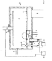
Die Erfindung wird nun anschliessend beispielsweise anhand der beigefügten Figuren und anhand von spezifischen Ausführungsbeispielen näher erläutert. Die beigefügte Fig. 1 zeigt dabei eine Hochvakuumanlage mit einer Funkenentladungsanordnung sowie eine Elektronenkanone. Fig.2 zeigt eine Prinzipskizze einer erfindungsgemässen Anlage, geeignet für die Durchführung der Beispiele 4 und 5.The invention will now be described, for example, with reference to the accompanying figures and specific Exemplary embodiments explained in more detail. The attached Fig. 1 shows a high vacuum system with a Spark discharge arrangement and an electron gun. 2 shows a schematic diagram of an inventive Plant suitable for carrying out Examples 4 and 5.
In einer Hochvakuumanlage 9 mit der entsprechenden Pumpöffnung 10 für das Evakuieren der Vakuumanlage 9
ist eine konventionelle Elektronenkanone 6 montiert, welche mittels einer Wasserkühlung 7, 8 gekühlt wird. Die Elektronenkanone
6 ist derart angeordnet, dass ein von der Elektronenkanone emittierter Elektronenstrahl, geführt durch
die Polschuhe eines Elektromagneten 5, auf das rotierende, durch einen Isolator 4 vom Anlagenboden isoliert montierte
Target 1 trifft, das ebenfalls mittels Wasserkühlung 2,3 gekühlt wird.In a
Das Target 1 dient gleichzeitig als Kathode der Funkenentladung. Diese Funkenentladung umfasst eine wassergekühlte
Anode 12 mit einer Wasserkühlung 14, die über einen Isolator 13 von der Anlage isoliert ist. In einer beispielsweise
ausgeführten erfindungsgemässen Anordnung umfasst die Anode 12 die Ausmasse 30 x 10cm und ist in einer
Entfernung von ca. 10cm vom Target 1 montiert.Target 1 also serves as the cathode for spark discharge. This spark discharge includes a water-cooled one
Ein Zwischenboden 11 dient als Druckstufe für den Fall, dass über einen Gaseinlass 16 Reaktiv- oder Edelgase
eingelassen werden, so dass der Druck in der Beschickungskammer 21 über den für die Elektronenkanone maximal
zulässigen Druck steigt.An
Die Schaltung 15 symbolisiert die Stromversorgung des Funkens, wobei es sich beispielsweise um einen Hochstromgenerator
handeln kann. Die zu beschichtenden Gegenstände, wie beispielsweise optischen Substrate, werden
auf dem rotierenden Substrathalter 17 befestigt, der über Isolierungen 18 gegenüber der Anlage isoliert ist. Die Drehdurchführung
19 ist wassergekühlt. Der Substrathalter kann mittels einer Spannungsquelle 20 auf ein gegenüber der
Kathode negatives Potential gelegt werden.The
Wenn nun die Hochvakuumanlage 9 in Betrieb genommen wird, wird mittels der Elektronenkanone und den Polschuhen
des Elektromagneten 5 ein Elektronenstrahl auf die Oberfläche des Targets 1 geführt. Dadurch wird auf der
Targetoberfläche ein punktförmiger Flecken des zu verdampfenden Materials angeschmolzen und dieses Material
teilweise verdampft. Durch die Stossionisation des verdampfenden Materials mit den Elektronen des Elektronenstrahls
wird eine partielle lonisierung des Dampfes erreicht. Diese lonisierung ist ausreichend zur Zündung des Funkens durch
Anlegen der Leerlaufspannung zwischen den beiden Elektroden des Funkens resp. zwischen den Targets 1 und der
Anode 12. Der überspringende Funken resp. Lichtbogen springt im übrigen auf den vorgeschmolzenen, punktförmigen
Flecken an der Targetoberfläche.If the
Die Elektronenstrahlkanone 6 ist bevorzugt derart in der Hochvakuumanlage 9 angeordnet, dass der Elektronenstrahl
beliebig auf der Oberfläche des Targets 1 geführt werden kann. Durch diese Bewegung kann nun auch der
Lichtbogen in beliebiger Art und Weise auf der Targetoberfläche geführt werden, wodurch gleichmässiges und spritzerfreies
Verdampfen des Targetmaterials möglich ist. Bei Unterbrechen des Lichtbogens wird durch das punktförmige
Aufschmelzen der Targetoberfläche automatisch ein neuer Funken gezündet und der Lichtbogen aufrechterhalten. Die
Beschichtung eines Substrates, welches auf der Substrathalterung 17 angeordnet ist, erfolgt gemäss allgemein bekannter
Verfahrenstechniken.The
Anstelle einer Elektronenkanone 6 kann selbstverständlich auch ein Laser in der Hochvakuumanlage angeordnet
werden, wodurch nun die Oberfläche des Targets 1 durch einen entsprechenden Laserstrahl örtlich angeschmolzen
wird. Wiederum erfolgt die Zündung des Funkens durch die notwendige lonisierung des verdampften Materials oder
aber der Restgasatmosphäre in der Beschickungskammer 21. Auch bei Anbringen eines Lasers anstelle einer Elektronenstrahlkanone
ist es möglich, durch Führen des entsprechenden Fleckens auf der Oberfläche des Targets nach
Zünden des Lichtbogens diesen auf der Targetoberfläche zu führen, um ein gleichmässiges und spritzerfreies Abtragen
der Targetoberfläche zu gewährleisten.Instead of an
Die in Fig. 1 beispielsweise dargestellte Verwendung einer Elektronenstrahlkanone eignet sich zum Zünden resp. Führen eines Funkens in einer x-beliebigen Hochvakuumanlage.The use of an electron beam gun shown in Fig. 1 is suitable for firing or. Carrying a spark in any high vacuum system.
Eine kubische Bedampfungsanlage vom Typ BAI 640 K wurde wie folgt ausgerüstet: In ihrem Boden, dezentriert, war ein wassergekühlter Tiegel eingebaut. Neben dem Tiegel im Boden war eine Elektronenstrahlkanone mit axialem Magnetfeld angebracht, deren Kathodenraum differentiell abgepumpt wurde. Der Abstand vom Austritt des Elektronenstrahls zum Kathodenmittelpunkt betrug 100mm. Die Elektronenstrahlkanone hatte eine maximale Leistung von 8 kW. Der Tiegel war aus Kupfer gefertigt, wassergekühlt und hatte einen Durchmesser von 80mm. Er war elektrisch sowohl vom Kammerboden als auch von der Masse der Kanone isoliert. Mit einem Elektromotor konnte er in Rotation versetzt werden. Der Tiegel wurde mit einem Kabel, das isoliert in die Anlage eingeführt worden war, an den negativen Pol eines Gleichspannungsspeisegerätes von der Art eines Schweisstransformators (max. 250 A) mit Kupferkabeln von 10mm angeschlossen. Der positive Pol des Speisegerätes wurde mit einer getrennten, elektrisch isolierten und wassergekühlten Durchführung an eine wassergekühlte Hilfsanode angeschlossen. Diese war rechteckig, 250 x 100mm, und stand wimpelartig in einem Abstand von 60mm vom Tiegel. Gegenüber dem Boden befand sich ein Drehteller, dessen Achse durch das Anlagenzentrum führte, auf dem Prüfkörper angebracht waren. Der Tiegel wurde mit 350g Titan chargiert und die Anlage geschlossen und abgepumpt. Die Prüfkörper wurden mit einer für die Werkzeugbeschichtung üblichen Methode geheizt und ihre Oberfläche in einem Argonplasma gereinigt. Danach wurde die Elektronenstrahlkanone eingeschaltet und ihre Leistung auf 700 Watt hochgefahren. Die Spannung zwischen Filament und Tiegel betrug 10.6 kV. Der Tiegel wurde mit einer Frequenz von 2 Umdrehungen/Minute in Rotation versetzt. Der Brennfleck mit einem Durchmesser von etwa 1mm wurde auf den der Austrittsöffnung des Elektronenstrahls näher liegenden Sektor des Tiegels fokussiert. Der Druck in der Kammer war kleiner als 0.002 Pa. Danach wurde der Schweisstransformator eingeschaltet. Seine Leerlaufspannung von 130 V reichte, um eine Entladung zu beenden. Der Strom wurde auf 200 A geregelt. Die Betriebsspannung betrug 41 V. In der Schmelze bildete sich ein kreisförmiger Graben, dessen Grund dem Fusspunkt des Elektronenstrahls entsprach. Ueber dieser Schmelze bildete sich ein lichtstarkes Plasma aus. Die Substrate wurden durch ein zusätzliches Speisegerät auf eine Spannung von -80 V gegenüber dem Tiegelpotential gelegt. Der lonenstrom auf dem Substratträger betrug 8 A. Ohne Schweisstransformator war der Substratstrom zu gering, um gemessen werden zu können. Nach 15 Minuten wurden die Stromversorgungen abgeschaltet und die Anlage geflutet. Auf den Substraten befand sich eine feinkristalline Schicht von 4 µm Titan. Die Oberflächenrauhigkeit der Prüfkörper blieb unverändert und entsprach einer mittleren Rauhtiefe von Ra, 0.04 µm.A BAI 640 K cubic steaming system was equipped as follows: In its bottom, decentred, a water-cooled crucible was installed. Next to the crucible in the bottom was an electron gun with an axial one Magnetic field attached, the cathode chamber was pumped out differentially. The distance from the exit of the electron beam to the center of the cathode was 100 mm. The electron beam gun had a maximum power of 8 kW. The crucible was made of copper, water-cooled and had a diameter of 80mm. It was electric isolated from the chamber floor as well as from the mass of the cannon. With an electric motor, he could rotate be transferred. The crucible was connected to the negative with a cable that had been inserted into the system in isolation Pole of a DC voltage supply device of the type of a welding transformer (max. 250 A) with copper cables connected by 10mm. The positive pole of the power supply was with a separate, electrically insulated and water-cooled bushing connected to a water-cooled auxiliary anode. This was rectangular, 250 x 100mm, and stood like a pennant at a distance of 60mm from the crucible. There was a across the floor Turntable, the axis of which led through the plant center, were attached to the test specimen. The crucible was Charged with 350g titanium and the system closed and pumped out. The test specimens were used for coating the tools heated the usual method and cleaned its surface in an argon plasma. After that the Electron beam gun switched on and its power increased to 700 watts. The tension between filament and crucible was 10.6 kV. The crucible was rotated at a frequency of 2 revolutions / minute. The Focal spot with a diameter of about 1mm became closer to the exit opening of the electron beam lying sector of the crucible. The pressure in the chamber was less than 0.002 Pa. Then the welding transformer switched on. Its open-circuit voltage of 130 V was sufficient to end a discharge. The current was regulated to 200 A. The operating voltage was 41 V. A circular trench formed in the melt, the bottom of which corresponded to the base of the electron beam. A bright light was formed over this melt Plasma off. The substrates were adjusted to a voltage of -80 V by an additional power supply Crucible potential. The ion current on the substrate carrier was 8 A. Without the welding transformer, the substrate current was too low to be measured. The power supplies were switched off after 15 minutes and flooded the facility. There was a fine crystalline layer of 4 µm titanium on the substrates. The surface roughness the test specimen remained unchanged and corresponded to an average roughness depth of Ra, 0.04 µm.
Es wurde der gleiche Aufbau wie im Beispiel 1 benutzt. Der Tiegel wurde mit 330g Titan chargiert. Danach wurde vorerst wie in Beispiel 1 vorgegangen. Die Leistung der Elektronenstrahlkanone wurde auf 7.4 kW geregelt. Die Tegelrotation wurde nicht eingeschaltet. Der Elektronenstrahl wurde auf die Tiegelmitte fokussiert. Der Durchmesser seines Brennflecks betrug etwa 7mm. Der Elektronenstrahl wurde mit einer Automatik mit einer Frequenz von 30 Hertz gewobbelt. Danach wurde Argon, und zwar 40 standard cm3/min, eingelassen. Danach wurde der Schweisstransformator zugeschaltet und sein Strom auf 110 A hochgeregelt. Die Betriebsspannung betrug 10 V. Ueber der Schmelze bildete sich wieder ein lichtstarkes Plasma, das der Wobbelbewegung folgte. Es wurde Stickstoff zugelassen, und zwar 420 standard cm3 /min. Die Substrate wurden auf eine Gleichspannung von -20 V gelegt. Nach einer Stunde wurden die Strom- und Gasversorgungen abgeschaltet und die Anlage geöffnet. Auf den Probescheiben waren 8 µm stöchiometrisches goldfarbenes Titannitrid abgeschieden. Die Härte der Schicht betrug 2300 HV Sie wies einen ausgezeichneten Widerstand gegenüber Erosion auf. Die Prozesstemperatur hatte 220°C nicht überschritten.The same structure as in Example 1 was used. The crucible was charged with 330g titanium. After that, the procedure was initially as in Example 1. The power of the electron beam gun was regulated at 7.4 kW. The Tegel rotation was not switched on. The electron beam was focused on the center of the crucible. The diameter of his focal spot was about 7mm. The electron beam was wobbled with an automatic at a frequency of 30 Hertz. Thereafter, argon, namely 40 standard cm 3 / min, was admitted. The welding transformer was then switched on and its current regulated up to 110 A. The operating voltage was 10 V. Above the melt, a bright plasma was again formed, which followed the wobble movement. Nitrogen was approved, namely 420 standard cm 3 / min. The substrates were placed on a DC voltage of -20 V. After an hour, the electricity and gas supplies were switched off and the system opened. 8 µm stoichiometric gold-colored titanium nitride was deposited on the test disks. The hardness of the layer was 2300 HV. It had excellent resistance to erosion. The process temperature had not exceeded 220 ° C.
Eine kubische Bedampfungsanlage vom Typ BAI 640 K wurde wie folgt ausgerüstet: In ihrem Boden, dezentriert, war ein wassergekühlter Tiegel eingebaut. Neben dem Tiegel im Boden war eine Elektronenstrahlkanone mit axialem Magnetfeld angebracht, deren Kathodenraum differentiell abgepumpt wurde. Der Abstand vom Austritt des Elektronenstrahls zum Kathodenmittelpunkt betrug 160mm. Die Elektronenstrahlkanone hatte eine maximale Leistung von 8 kW. Der Tiegel war aus Kupfer gefertigt, wassergekühlt und hatte einen Durchmesser von 80mm. Er war elektrisch sowohl vom Kammerboden als auch von der Masse der Kanone isoliert. Mit einem Elektromotor konnte er in Rotation versetzt werden. Der Tiegel wurde mit einem Kabel, das isoliert in die Anlage eingeführt worden war, an den negativen Pol eines Gleichspannungsspeisegerätes von der Art eines Schweisstransformators (max. 250 A) mit Kupferkabeln von 10mm angeschlossen. Der positive Pol des Speisegerätes wurde mit einer getrennten, elektrisch isolierten und wassergekühlten Durchführung an eine wassergekühlte Hilfsanode angeschlossen. Diese war rechteckig, 250 x 100mm, und stand wimpelartig in einem Abstand von 60mm vom Tiegel. Gegenüber vom Boden befand sich eine Kalotte mit Glasscheiben. Der Tiegel wurde mit 60g Silicium chargiert und die Anlage geschlossen und abgepumpt. Danach wurde in die Kammer Sauerstoff eingelassen, dessen Fluss so geregelt war, dass der Druck in der Anlage 0,09Pa nicht überstieg. Danach wurde die Elektronenstrahlkanone eingeschaltet und ihre Leistung auf 600W hochgefahren. Etwa gleichzeitig wurde der Tiegel in Rotation versetzt und der Schweisstransformator zugeschaltet. Dessen Strom wurde auf 140 Ampère hochgeregelt. Nach 30 Minuten wurde die Stromversorgung abgeschaltet. Beim Oeffnen der Anlage hat sich auf den Glasscheiben eine transparente Siliciumoxidschicht niedergeschlagen. A BAI 640 K cubic steaming system was equipped as follows: In its bottom, decentred, a water-cooled crucible was installed. Next to the crucible in the bottom was an electron gun with an axial one Magnetic field attached, the cathode chamber was pumped out differentially. The distance from the exit of the electron beam to the center of the cathode was 160 mm. The electron beam gun had a maximum power of 8 kW. The crucible was made of copper, water-cooled and had a diameter of 80mm. It was electric isolated from the chamber floor as well as from the mass of the cannon. With an electric motor, he could rotate be transferred. The crucible was connected to the negative with a cable that had been inserted into the system in isolation Pole of a DC voltage supply device of the type of a welding transformer (max. 250 A) with copper cables connected by 10mm. The positive pole of the power supply was with a separate, electrically insulated and water-cooled bushing connected to a water-cooled auxiliary anode. This was rectangular, 250 x 100mm, and stood like a pennant at a distance of 60mm from the crucible. There was one across the floor Calotte with glass panes. The crucible was charged with 60 g silicon and the system was closed and pumped out. Then oxygen was admitted into the chamber, the flow of which was regulated so that the pressure in the system Did not exceed 0.09 Pa. The electron beam gun was then switched on and its power increased to 600W. At about the same time, the crucible was set in rotation and the welding transformer switched on. Whose Electricity was ramped up to 140 amps. The power supply was switched off after 30 minutes. When opening The system has a transparent silicon oxide layer deposited on the glass panes.
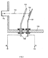
Wie in Fig. 2 als Prinzipskizze dargestellt, wurde in einer kubischen Anlage BAI 760 K, 200mm vom Anlagenzentrum
entfernt, ein wassergekühlter, kreisförmiger Kathodenhalter 101 so montiert (Durchmesser 120mm, Dicke 10mm),
dass der Winkel zwischen der Oberflächennormalen und der Anlagenachse 70° betrug. Auf diesen Kathodenhalter
wurde ein 3mm dickes, rundes Titantarget 102 (Durchmesser 48mm), das auf einen runden (60mm Durchmesser),
12mm dicken Kupferblock aufgelötet war, derart aufgeschraubt, dass zwischen Titantarget und Kathodenhalter ein
guter elektrischer Kontakt hergestellt werden konnte. Im Abstand von 35mm von der Kathode wurde eine isoliert durch
den Anlagenboden 106 durchgeführte, wassergekühlte 108 ringförmige (Innendurchmesser 70mm) Anode 103 mit
kreisförmigem Querschnitt (Durchmesser 12mm) parallel zur Kathode montiert. Die Kathode war geerdet und mit dem
negativen Pol 110 eines Schweisstransformators (max. 250 A) verbunden, die Anode 103 wurde mit dem positiven
Pol 111 dieser Stromquelle verbunden. Der Laserstrahl 113 eines gepulsten Nd:YAG Lasers (500 W) wurde durch ein
Fenster 114 (Durchmesser 40mm), das beidseitig mit einer Antireflexschicht beschichtet war, in die Anlage geführt
und durch die Anode hindurch auf die Kathodenoberfläche fokussiert. Der Abstand zwischen dem Fenster und der
Kathode betrug 280mm. Der Laserstrahl wurde ausserhalb der Anlage mittels eines rotierenden dielektrischen Spiegels,
dessen Oberfläche einen Winkel von 0,5° mit der Rotationsachse bildete, um 90° umgelenkt. Durch diese Rotation
konnte der Brennfleck (Durchmesser 0.7mm) des Laserstrahles auf dem Titantarget rotiert werden. Die Rotationsgeschwindigkeit
war einstellbar zwischen 0 und 6000 U/min. Die Fokussierung wurde mittels einer bikonvexen, beidseitig
antireflexbeschichteten Linse mit einer Brennweite von 500mm vor dem rotierenden Spiegel bewerkstelligt.As shown in Fig. 2 as a schematic diagram, was in a cubic plant BAI 760 K, 200mm from the plant center
removed, a water-cooled,
Nach Erreichen von 2*10-3 Pa wurde durch Einschalten des Speisegerätes eine Spannung von 100 V zwischen Kathode und Anode gelegt. Der Funke wurde darauf mittels eines Laserpulses von 6 Millisekunden Dauer und einer Energie von 30.5 Joule gezündet. Danach lief der ungeführte Funke bei ca. 20 V und 90 A. Es wurde festgestellt, dass die Zündbedingung (Schwellenergie des Laserpulses) stark von der Oberflächenbeschaffenheit des Targets (Reflexionsvermögen) und von der Rotationsgeschwindigkeit des Laserstrahles abhängt.After reaching 2 * 10 -3 Pa, a voltage of 100 V was applied between the cathode and anode by switching on the power supply. The spark was then ignited by means of a laser pulse lasting 6 milliseconds and an energy of 30.5 joules. Then the unguided spark ran at approx. 20 V and 90 A. It was found that the ignition condition (threshold energy of the laser pulse) strongly depends on the surface condition of the target (reflectivity) and on the rotation speed of the laser beam.
Das Zeitintervall zwischen Pulsen kann so gewählt werden, dass die Bodenentladung kontinuierlich brennt. Dies erlaubt ein Führen des Funkens auf der Kathodenfläche. Anstelle des Spiegels können auch andere optische Elemente, wie Hohlspiegel oder Gitter, verwendet werden. Anstelle des Nd:YAG Lasers können auch Gas oder Halbleiterlaser verwendet werden.The time interval between pulses can be selected so that the bottom discharge burns continuously. This allows the spark to be guided on the cathode surface. Instead of the mirror, other optical elements, such as concave mirrors or gratings can be used. Instead of the Nd: YAG laser, gas or semiconductor lasers can also be used be used.
In einer kubischen Anlage BAI 760 K wurde, 200mm vom Anlagenzentrum entfernt, ein wassergekühlter, kreisförmiger Kathodenhalter so montiert (Durchmesser 120mm, Dicke 10mm), dass der Winkel zwischen der Oberflächennormalen und der Anlagenachse 70° betrug. Auf diesen Kathodenhalter wurde ein 5mm dickes, rechteckiges Zinntarget, das auf eine Kupferplatte der Dicke 5mm aufgelötet war, derart aufgeschraubt, dass zwischen Zinntarget und Kathodenhalter ein guter elektrischer Kontakt hergestellt werden konnte. Im Abstand von 35mm von der Kathode wurde eine isoliert durch den Anlagenboden durchgeführte wassergekühlte, ringförmige (Innendurchmesser 70mm) Anode mit kreisförmigem Querschnitt (Durchmesser 12mm) parallel zur Kathode montiert.In a BAI 760 K cubic system, a water-cooled, circular one was located 200 mm from the system center Mounted cathode holder (diameter 120mm, thickness 10mm) so that the angle between the surface normal and the system axis was 70 °. A 5 mm thick, rectangular tin target was placed on this cathode holder, which was soldered onto a copper plate with a thickness of 5mm, screwed in such a way that between the tin target and A good electrical contact could be made to the cathode holder. At a distance of 35mm from the cathode an insulated, water-cooled, ring-shaped (inner diameter 70mm) anode through the bottom of the system with a circular cross section (diameter 12mm) mounted parallel to the cathode.
Die Kathode (und somit das Zinntarget) war geerdet und mit dem negativen Pol eines Schweisstransformators (max. 250 A) verbunden. Die Anode wurde mit dem positiven Pol dieser Stromquelle verbunden. Der Laserstrahl eines gepulsten Nd:YAG Lasers (500 W) wurde durch ein Fenster (Durchmesser 40mm), das beidseitig mit einer Antireflexschicht beschichtet war, in die Anlage geführt und durch die Anode hindurch auf die Kathodenoberfläche fokussiert. Der Abstand zwischen dem Fenster und der Kathode betrug 280mm. Die Fokussierung des Laserstrahls erfolgte mittels einer beidseitig mit einer Antireflexschicht versehenen Linse (Brennweite 500mm), die starr mit dem Laser verbunden war. Die Bewegung des fokussierten Laserstrahles innerhalb einer Fläche von 50mm Durchmesser auf dem Target wurde bewerkstelligt, indem der Laser ausserhalb der Anlage auf einem massiven Tisch, der in zwei voneinander unabhängigen Richtungen bewegt werden konnte, montiert wurde.The cathode (and thus the tin target) was grounded and with the negative pole of a welding transformer (max. 250 A) connected. The anode was connected to the positive pole of this power source. The laser beam one Pulsed Nd: YAG laser (500 W) was through a window (diameter 40mm), which is coated on both sides with an anti-reflective layer was coated, led into the system and focused through the anode onto the cathode surface. The distance between the window and the cathode was 280mm. The laser beam was focused using a lens with an anti-reflective coating on both sides (focal length 500mm), which is rigidly connected to the laser was. The movement of the focused laser beam within an area of 50mm in diameter on the target was accomplished by placing the laser outside the system on a massive table that separated into two independent directions could be moved.
Nach Erreichen von 2*10-3 Pa wurde Argon in die Vakuumkammer eingelassen, bis ein Druck von 2*10-1 Pa erreicht wurde. Durch Einschalten des Speisegerätes wurde eine Spannung von 100 V zwischen Kathode und Anode gelegt. Der Funke konnte mittels eines Laserpulses von 6 Millisekunden Dauer und einer Energie von 2 J gezündet werden und lief auf dem Zinntarget.After reaching 2 * 10 -3 Pa, argon was let into the vacuum chamber until a pressure of 2 * 10 -1 Pa was reached. By switching on the power supply, a voltage of 100 V was applied between the cathode and the anode. The spark could be ignited using a laser pulse lasting 6 milliseconds and an energy of 2 J and ran on the tin target.
Danach lief der Funke bei ca. 20 V und 90 A. Es wurde festgestellt, dass die Zündbedingung (Schwellenergie des Laserpulses) stark von der Oberflächenbeschaffenheit des Targets (Reflexionsvermögen) und, evidenterweise, von der Rotationsgeschwindigkeit des Laserstrahles abhängt.The spark then ran at approx. 20 V and 90 A. It was found that the ignition condition (threshold energy of the Laser pulse) strongly from the surface quality of the target (reflectivity) and, evidently, from depends on the speed of rotation of the laser beam.
In einer kubischen Anlage BAI 760 K wurde, 200mm vom Anlagenzentrum entfernt, ein wassergekühlter, kreisförmiger Kathodenhalter so montiert (Durchmesser 120mm, Dicke 10mm), dass der Winkel zwischen der Oberflächennormalen und der Anlagenachse 70° betrug. Auf diesen Kathodenhalter wurde ein 5mm dickes, rundes Wolframtarget (Durchmesser 30mm) aufgeklemmt, so dass zwischen Wolframtarget und Kathodenhalter ein guter elektrischer Kontakt hergestellt werden konnte. Im Abstand von 35mm von der Kathode wurde eine isoliert durch den Anlagenboden durchgeführte, wassergekühlte, ringförmige (Innendurchmesser 70mm) Anode mit kreisförmigem Querschnitt (Durchmesser 12mm) parallel zur Kathode montiert.In a BAI 760 K cubic system, a water-cooled, circular one was located 200 mm from the system center Mounted cathode holder (diameter 120mm, thickness 10mm) so that the angle between the surface normal and the system axis was 70 °. A 5mm thick, round tungsten target was placed on this cathode holder (Diameter 30mm), so that there is good electrical contact between the tungsten target and the cathode holder could be made. At a distance of 35mm from the cathode, one was isolated through the bottom of the system carried out, water-cooled, ring-shaped (inner diameter 70mm) anode with circular cross-section (diameter 12mm) mounted parallel to the cathode.
Die Kathode war geerdet und mit dem negativen Pol eines Schweisstransformators (max. 250 A) verbunden. Die
Anode wurde mit dem positiven Pol dieser Stromquelle verbunden. Der Laserstrahl eines gepulsten Nd:YAG Lasers
(500 W) wurde durch ein Fenster (Durchmesser 40mm), das beidseitig mit einer Antireflexschicht beschichtet war, in
die Anlage geführt und durch die Anode hindurch auf die Kathodenoberfläche fokussiert. Der Abstand zwischen dem
Fenster und der Kathode betrug 280mm. Die Fokussierung des Laserstrahles (Durchmesser des Laserstrahles auf
dem Target: 0.65mm) erfolgte durch eine ausserhalb der Anlage montierte, beidseitig antireflexbeschichtete Bikonvexlinse
(Brennweite 500mm), die so bewegt werden konnte, dass der Brennpunkt des Laserstrahles beliebig auf dem
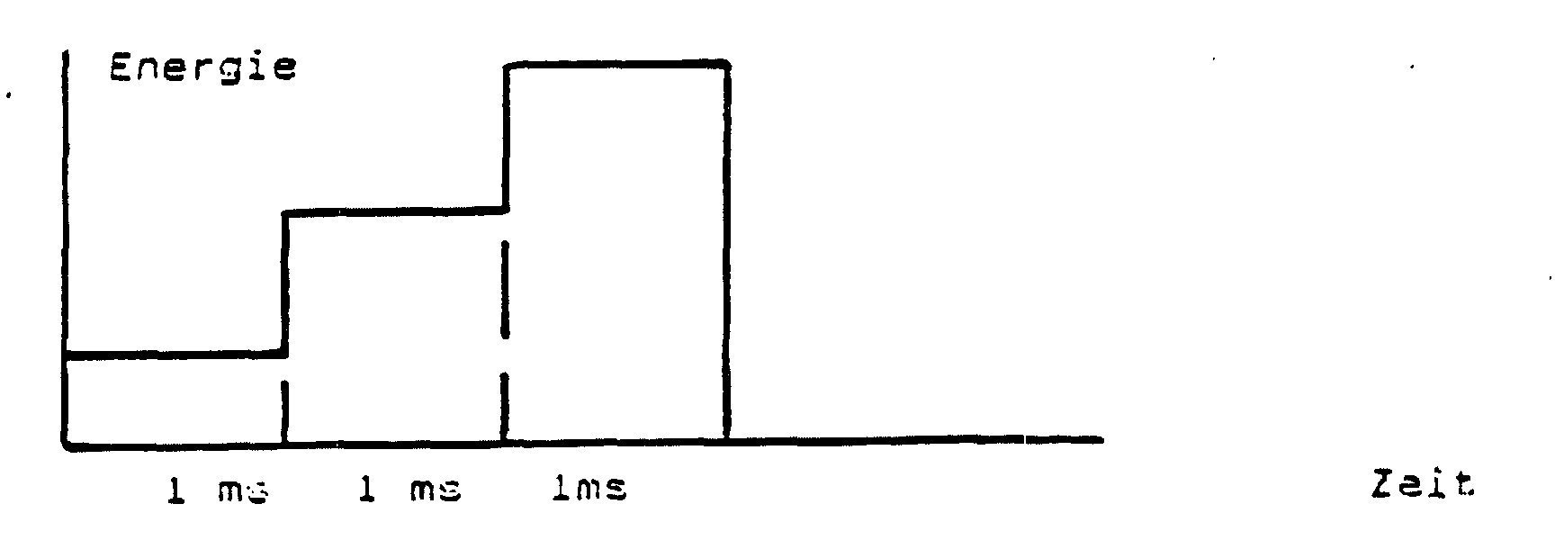
W-Target bewegt werden konnte. Die Steuerung der Bewegung erfolgte computergesteuert. Nach Ereichenvon 2*10-3
Pa wurde durch Einschalten des Speisegerätes eine Spannung von 100 V zwischen Kathode und Anode gelegt. Der
Funke wurde darauf mittels eines treppenförmigen Laserpulses (siehe Skizze) von 3 Millisekunden totaler Dauer und
einer Energie von 7.5 J gezündet. Der Funke wurde mittels eines Speicherkathodenstrahloszilloskopes aufgezeichnet.
Claims (21)
- Device for vaporising material in a vacuum by means of an arc with a target (1, 102) which has a material to be vaporised at least on part of its surface, where the arc discharge is operated in an area in which an essential part of the arc current flows mostly through small spots on the target surface and the target is connected as a cathode of the spark or arc, characterised in that the device also has an electron beam gun (6) or a continuously operated laser (113, 114) to generate a local vapour cloud on the target surface and means of guiding the electron beam or laser beam over the target surface in order to stabilise and guide the base point of the arc, where in the case of a pulsed laser the time interval between the pulses is selected such that the arc discharge burns continuously in order to guarantee an even and splash-free removal of the target surface.
- Device according to claim 1, characterised in that the object lens of the laser is arranged mobile such that the laser beam can be guided on the target surface.
- Device according to any of claims 1 or 2, characterised in that a movable mirror is arranged to allow the cathode spot of the laser to move such that the laser beam can be guided on the target surface.
- Device according to any of claims 1 to 3, characterised in that the target is arranged movably.
- Device according to any of claims 1 to 4 for igniting the vaporization arc on the target, characterised in that the electron beam gun or laser for generating a melted spot or forming a local vapour cloud is provided over a small area of the target surface which is sufficient to ignite the arc.
- Device according to any of claims 1 to 5, characterised by a laser lens with a focal length greater than 40 mm.
- Device according to any of claims 5 or 6, characterised by a pulsed laser to ignite the arc.
- Device for vaporising material in a vacuum by means of an arc on a target (1, 102) connected as a cathode which has a material to be vaporised on at least one part of its surface, where the arc discharge is operated in an area where an essential part of the arc current flows mostly through small spots on the target surface, characterised in that by means of an electron beam or a continuously operated laser a local vapour cloud is generated on the target surface such that the base point of the arc or spark is stabilised in this vapour cloud and guided with it, where in the case of a pulsed laser the time interval between the pulses is selected such that the arc discharge burns continuously in order to guarantee an even and splash-free removal of the target surface.
- Process according to claim 8, characterised in that a pool is created below the vapour cloud on the target surface.
- Process according to any of claims 8 or 9, characterised in that the electron beam or the laser beam is guided on the target surface.
- Process according to any of claims 8 to 10, characterised in that at the temporal middle point, the operating power of the arc discharge exceeds the operating power of the electron beam gun or laser and that the greatest part of the material is vaporized by means of the arc of the arc discharge.
- Process according to any of claims 8 to 11, characterised in that the energy density of the electron beam or laser beam is controlled such that a discharge current of over 30 Ampere is possible with a discharge voltage of only 10 to 15 Volt.
- Process according to any of claims 8 to 12, characterised in that by means of the electron beam gun or laser a melted spot is generated on the target surface or a local vapour cloud over a small area of the target surface which is sufficient to ignite a spark or the arc.
- Process according to claim 13, characterised in that the size of the ignition spot when an electron beam is used is less than 10 mm2, preferably less than 1 mm2, or when a laser is used less than 0.3 mm2, preferably less than 0.1 mm2.
- Process according to any of claims 13 or 14, characterised in that the ignition of the light arc is repeated at least almost regularly.
- Process according to any of claims 8 to 15, characterised in that in a vaporization chamber lying above the target, a diluted atmosphere of inert gas, oxygen, nitrogen, a gaseous carbon compound, a metal organic gaseous or a boron-containing gaseous compound is maintained.
- Process according to any of claims 9 to 16, characterised in that the target surface consists of an easily melting material and the electron beam or laser beam is defocussed so strongly that the pool around the arc base of the arc discharge gradually forms a hopper into the base of which runs fluid target material such that the arc is stabilised without guidance.
- Process according to any of claims 8 to 17, characterised in that the electron beam or laser cathode spot is moved so quickly that the self-generated movement of the arc discharge base point is suppressed.
- Use of the process according to any of claims 13 to 15 for sequential ignition of several targets with one beam.
- Use of the process according to any of claims 8 to 18, to vaporise substrates by means of a plasma arc.
- Use according to claim 20, characterised in that in the vaporization chamber is maintained a nitrogen, oxygen or gaseous carbon compound-containing atmosphere which reacts with the condensing material on the surface at least partly to form its carbides, oxides and nitrides or mixtures thereof.
Applications Claiming Priority (4)
| Application Number | Priority Date | Filing Date | Title |
|---|---|---|---|
| DE4006458 | 1990-03-01 | ||
| DE4006456 | 1990-03-01 | ||
| DE4006458 | 1990-03-01 | ||
| DE19904006456 DE4006456C1 (en) | 1990-03-01 | 1990-03-01 | Appts. for vaporising material in vacuum - has electron beam gun or laser guided by electromagnet to form cloud or pre-melted spot on the target surface |
Publications (4)
| Publication Number | Publication Date |
|---|---|
| EP0444538A2 EP0444538A2 (en) | 1991-09-04 |
| EP0444538A3 EP0444538A3 (en) | 1992-02-05 |
| EP0444538B1 EP0444538B1 (en) | 1996-12-04 |
| EP0444538B2 true EP0444538B2 (en) | 2002-04-24 |
Family
ID=25890680
Family Applications (1)
| Application Number | Title | Priority Date | Filing Date |
|---|---|---|---|
| EP91102573A Expired - Lifetime EP0444538B2 (en) | 1990-03-01 | 1991-02-22 | Device and procedure for vacuum evaporation of a material and utilisation of the procedure |
Country Status (6)
| Country | Link |
|---|---|
| EP (1) | EP0444538B2 (en) |
| JP (1) | JPH0641727A (en) |
| KR (1) | KR910016959A (en) |
| AT (1) | ATE146010T1 (en) |
| DE (1) | DE59108387D1 (en) |
| ES (1) | ES2095880T3 (en) |
Families Citing this family (7)
| Publication number | Priority date | Publication date | Assignee | Title |
|---|---|---|---|---|
| JPH0641727B2 (en) * | 1990-11-29 | 1994-06-01 | 晏弘 奥田 | Silencer for internal combustion engine |
| CH683776A5 (en) * | 1991-12-05 | 1994-05-13 | Alusuisse Lonza Services Ag | Coating a substrate surface with a permeation barrier. |
| DE4427585A1 (en) * | 1994-08-04 | 1996-02-08 | Leybold Ag | Coating system for electrically non-conductive metal oxide(s) |
| KR100426658B1 (en) * | 2002-01-31 | 2004-04-13 | 한국수력원자력 주식회사 | Coating system utilizing small electron gun |
| JP2010248574A (en) * | 2009-04-16 | 2010-11-04 | Ulvac Japan Ltd | Vapor deposition apparatus and vapor deposition method |
| US20150371833A1 (en) * | 2013-01-22 | 2015-12-24 | Nissin Electric Co., Ltd. | Plasma device, carbon thin film manufacturing method and coating method using plasma device |
| DE102019135749B4 (en) * | 2019-12-23 | 2024-02-08 | Ri Research Instruments Gmbh | Arc coating assembly and method |
Family Cites Families (6)
| Publication number | Priority date | Publication date | Assignee | Title |
|---|---|---|---|---|
| CH645137A5 (en) * | 1981-03-13 | 1984-09-14 | Balzers Hochvakuum | METHOD AND DEVICE FOR EVAPORATING MATERIAL UNDER VACUUM. |
| US4829153A (en) * | 1986-04-28 | 1989-05-09 | Battelle Memorial Institute | Welding arc initiator |
| DD272666B5 (en) * | 1988-05-31 | 1995-09-21 | Fraunhofer Ges Forschung | Process for producing multiple layers by means of a vacuum arc evaporator |
| DE3901401C2 (en) * | 1988-03-01 | 1996-12-19 | Fraunhofer Ges Forschung | Process for controlling a vacuum arc discharge |
| DD275883B5 (en) * | 1988-09-29 | 1995-10-19 | Fraunhofer Ges Forschung | Process for homogeneous layer deposition by means of arc discharge |
| DD277472A1 (en) * | 1988-11-30 | 1990-04-04 | Hochvakuum Dresden Veb | METHOD FOR OPERATING A VACUUM ARC DISCHARGE EVAPORATOR |
-
1991
- 1991-02-22 DE DE59108387T patent/DE59108387D1/en not_active Expired - Lifetime
- 1991-02-22 AT AT91102573T patent/ATE146010T1/en not_active IP Right Cessation
- 1991-02-22 EP EP91102573A patent/EP0444538B2/en not_active Expired - Lifetime
- 1991-02-22 ES ES91102573T patent/ES2095880T3/en not_active Expired - Lifetime
- 1991-02-28 KR KR1019910003358A patent/KR910016959A/en not_active Application Discontinuation
- 1991-03-01 JP JP3036229A patent/JPH0641727A/en active Pending
Also Published As
| Publication number | Publication date |
|---|---|
| EP0444538A2 (en) | 1991-09-04 |
| EP0444538B1 (en) | 1996-12-04 |
| JPH0641727A (en) | 1994-02-15 |
| DE59108387D1 (en) | 1997-01-16 |
| KR910016959A (en) | 1991-11-05 |
| ES2095880T3 (en) | 1997-03-01 |
| ATE146010T1 (en) | 1996-12-15 |
| EP0444538A3 (en) | 1992-02-05 |
Similar Documents
| Publication | Publication Date | Title |
|---|---|---|
| EP0158972B1 (en) | Method and apparatus for the vaporisation of a material in a vacuum chamber by an arc discharge | |
| DE4336681C2 (en) | Method and device for plasma-activated electron beam evaporation | |
| DE112004001728T5 (en) | Rectangular filtered vapor plasma source and method for controlling a vapor plasma flow | |
| DE10342239A1 (en) | Method and apparatus for generating extreme ultraviolet or soft x-ray radiation | |
| DE3206882A1 (en) | METHOD AND DEVICE FOR EVAPORATING MATERIAL UNDER VACUUM | |
| EP0285745A1 (en) | Process and apparatus for vacuum coating by means of an electric arc discharge | |
| DE3901401C2 (en) | Process for controlling a vacuum arc discharge | |
| DE4026494C2 (en) | ||
| EP0444538B2 (en) | Device and procedure for vacuum evaporation of a material and utilisation of the procedure | |
| DE19546827C2 (en) | Device for generating dense plasmas in vacuum processes | |
| US5238546A (en) | Method and apparatus for vaporizing materials by plasma arc discharge | |
| DE4006456C1 (en) | Appts. for vaporising material in vacuum - has electron beam gun or laser guided by electromagnet to form cloud or pre-melted spot on the target surface | |
| DE10084452B3 (en) | Arc source with rectangular cathode and method for guiding an arc spot | |
| DE3800680A1 (en) | Process and appliance for coating a substrate | |
| EP0776987B1 (en) | Vacuum coating apparatus with a crucible located in the vacuum chamber to receive the evaporation material | |
| DE4100541C1 (en) | ||
| EP0277341A2 (en) | Device for the application of an arc | |
| DE19600993A1 (en) | Appts. for high rate anodic evapn. for substrate coating | |
| EP0389506B1 (en) | Process for producing thin layers of a material composed of different chemical compounds which melts or sublimes at high temperatures on a substrate | |
| DE19724996C1 (en) | Plasma-activated electron beam vapour deposition | |
| DE4109213C1 (en) | Arc-source for vacuum coating system - comprises cathode housing with double walled shell, and thin base, target, cooling water supply, drain, etc. | |
| DE3222327A1 (en) | Vacuum vapour-deposition apparatus | |
| DD277178A3 (en) | METHOD FOR CONTROLLING VACUUM ARC FLASH | |
| DE102020124270A1 (en) | Process and device for anodic arc evaporation | |
| DE4409761A1 (en) | Appts. for plasma-supported evaporation in arc discharge plasma |
Legal Events
| Date | Code | Title | Description |
|---|---|---|---|
| PUAI | Public reference made under article 153(3) epc to a published international application that has entered the european phase |
Free format text: ORIGINAL CODE: 0009012 |
|
| AK | Designated contracting states |
Kind code of ref document: A2 Designated state(s): AT CH DE ES FR GB IT LI NL SE |
|
| PUAL | Search report despatched |
Free format text: ORIGINAL CODE: 0009013 |
|
| AK | Designated contracting states |
Kind code of ref document: A3 Designated state(s): AT CH DE ES FR GB IT LI NL SE |
|
| 17P | Request for examination filed |
Effective date: 19920619 |
|
| 17Q | First examination report despatched |
Effective date: 19941212 |
|
| GRAG | Despatch of communication of intention to grant |
Free format text: ORIGINAL CODE: EPIDOS AGRA |
|
| GRAH | Despatch of communication of intention to grant a patent |
Free format text: ORIGINAL CODE: EPIDOS IGRA |
|
| GRAH | Despatch of communication of intention to grant a patent |
Free format text: ORIGINAL CODE: EPIDOS IGRA |
|
| GRAA | (expected) grant |
Free format text: ORIGINAL CODE: 0009210 |
|
| AK | Designated contracting states |
Kind code of ref document: B1 Designated state(s): AT CH DE ES FR GB IT LI NL SE |
|
| PG25 | Lapsed in a contracting state [announced via postgrant information from national office to epo] |
Ref country code: NL Free format text: LAPSE BECAUSE OF FAILURE TO SUBMIT A TRANSLATION OF THE DESCRIPTION OR TO PAY THE FEE WITHIN THE PRESCRIBED TIME-LIMIT Effective date: 19961204 |
|
| REF | Corresponds to: |
Ref document number: 146010 Country of ref document: AT Date of ref document: 19961215 Kind code of ref document: T |
|
| REF | Corresponds to: |
Ref document number: 59108387 Country of ref document: DE Date of ref document: 19970116 |
|
| ITF | It: translation for a ep patent filed |
Owner name: ING. ZINI MARANESI & C. S.R.L. |
|
| GBT | Gb: translation of ep patent filed (gb section 77(6)(a)/1977) |
Effective date: 19970125 |
|
| ET | Fr: translation filed | ||
| REG | Reference to a national code |
Ref country code: ES Ref legal event code: FG2A Ref document number: 2095880 Country of ref document: ES Kind code of ref document: T3 |
|
| PLBQ | Unpublished change to opponent data |
Free format text: ORIGINAL CODE: EPIDOS OPPO |
|
| PLBI | Opposition filed |
Free format text: ORIGINAL CODE: 0009260 |
|
| PLAV | Examination of admissibility of opposition |
Free format text: ORIGINAL CODE: EPIDOS OPEX |
|
| 26 | Opposition filed |
Opponent name: FRAUNHOFER-GESELLSCHAFT ZUR FOERDERUNG DER ANGEWAN Effective date: 19970827 |
|
| PLAV | Examination of admissibility of opposition |
Free format text: ORIGINAL CODE: EPIDOS OPEX |
|
| PLBF | Reply of patent proprietor to notice(s) of opposition |
Free format text: ORIGINAL CODE: EPIDOS OBSO |
|
| NLR1 | Nl: opposition has been filed with the epo |
Opponent name: FRAUNHOFER-GESELLSCHAFT ZUR FOERDERUNG DER ANGEWAN |
|
| PLBF | Reply of patent proprietor to notice(s) of opposition |
Free format text: ORIGINAL CODE: EPIDOS OBSO |
|
| PLAW | Interlocutory decision in opposition |
Free format text: ORIGINAL CODE: EPIDOS IDOP |
|
| PLAW | Interlocutory decision in opposition |
Free format text: ORIGINAL CODE: EPIDOS IDOP |
|
| REG | Reference to a national code |
Ref country code: GB Ref legal event code: IF02 |
|
| PGFP | Annual fee paid to national office [announced via postgrant information from national office to epo] |
Ref country code: SE Payment date: 20020206 Year of fee payment: 12 |
|
| PGFP | Annual fee paid to national office [announced via postgrant information from national office to epo] |
Ref country code: NL Payment date: 20020228 Year of fee payment: 12 |
|
| PUAH | Patent maintained in amended form |
Free format text: ORIGINAL CODE: 0009272 |
|
| STAA | Information on the status of an ep patent application or granted ep patent |
Free format text: STATUS: PATENT MAINTAINED AS AMENDED |
|
| 27A | Patent maintained in amended form |
Effective date: 20020424 |
|
| AK | Designated contracting states |
Kind code of ref document: B2 Designated state(s): AT CH DE ES FR GB IT LI NL SE |
|
| REG | Reference to a national code |
Ref country code: CH Ref legal event code: AEN Free format text: AUFRECHTERHALTUNG DES PATENTES IN GEAENDERTER FORM |
|
| GBTA | Gb: translation of amended ep patent filed (gb section 77(6)(b)/1977) | ||
| NLR2 | Nl: decision of opposition | ||
| PG25 | Lapsed in a contracting state [announced via postgrant information from national office to epo] |
Ref country code: ES Free format text: LAPSE BECAUSE OF FAILURE TO SUBMIT A TRANSLATION OF THE DESCRIPTION OR TO PAY THE FEE WITHIN THE PRESCRIBED TIME-LIMIT Effective date: 20020804 |
|
| ET3 | Fr: translation filed ** decision concerning opposition | ||
| PG25 | Lapsed in a contracting state [announced via postgrant information from national office to epo] |
Ref country code: SE Free format text: LAPSE BECAUSE OF NON-PAYMENT OF DUE FEES Effective date: 20020923 |
|
| NLV1 | Nl: lapsed or annulled due to failure to fulfill the requirements of art. 29p and 29m of the patents act | ||
| PGFP | Annual fee paid to national office [announced via postgrant information from national office to epo] |
Ref country code: AT Payment date: 20030212 Year of fee payment: 13 |
|
| PGFP | Annual fee paid to national office [announced via postgrant information from national office to epo] |
Ref country code: ES Payment date: 20030226 Year of fee payment: 13 |
|
| PGFP | Annual fee paid to national office [announced via postgrant information from national office to epo] |
Ref country code: CH Payment date: 20030509 Year of fee payment: 13 |
|
| PG25 | Lapsed in a contracting state [announced via postgrant information from national office to epo] |
Ref country code: AT Free format text: LAPSE BECAUSE OF NON-PAYMENT OF DUE FEES Effective date: 20040222 |
|
| PG25 | Lapsed in a contracting state [announced via postgrant information from national office to epo] |
Ref country code: LI Free format text: LAPSE BECAUSE OF NON-PAYMENT OF DUE FEES Effective date: 20040229 Ref country code: CH Free format text: LAPSE BECAUSE OF NON-PAYMENT OF DUE FEES Effective date: 20040229 |
|
| REG | Reference to a national code |
Ref country code: CH Ref legal event code: PL |
|
| PGFP | Annual fee paid to national office [announced via postgrant information from national office to epo] |
Ref country code: FR Payment date: 20050208 Year of fee payment: 15 |
|
| PGFP | Annual fee paid to national office [announced via postgrant information from national office to epo] |
Ref country code: GB Payment date: 20050216 Year of fee payment: 15 |
|
| PG25 | Lapsed in a contracting state [announced via postgrant information from national office to epo] |
Ref country code: IT Free format text: LAPSE BECAUSE OF NON-PAYMENT OF DUE FEES;WARNING: LAPSES OF ITALIAN PATENTS WITH EFFECTIVE DATE BEFORE 2007 MAY HAVE OCCURRED AT ANY TIME BEFORE 2007. THE CORRECT EFFECTIVE DATE MAY BE DIFFERENT FROM THE ONE RECORDED. Effective date: 20050222 |
|
| PG25 | Lapsed in a contracting state [announced via postgrant information from national office to epo] |
Ref country code: GB Free format text: LAPSE BECAUSE OF NON-PAYMENT OF DUE FEES Effective date: 20060222 |
|
| GBPC | Gb: european patent ceased through non-payment of renewal fee |
Effective date: 20060222 |
|
| REG | Reference to a national code |
Ref country code: FR Ref legal event code: ST Effective date: 20061031 |
|
| PG25 | Lapsed in a contracting state [announced via postgrant information from national office to epo] |
Ref country code: FR Free format text: LAPSE BECAUSE OF NON-PAYMENT OF DUE FEES Effective date: 20060228 |
|
| PLAB | Opposition data, opponent's data or that of the opponent's representative modified |
Free format text: ORIGINAL CODE: 0009299OPPO |
|
| PGFP | Annual fee paid to national office [announced via postgrant information from national office to epo] |
Ref country code: DE Payment date: 20100303 Year of fee payment: 20 |
|
| REG | Reference to a national code |
Ref country code: DE Ref legal event code: R071 Ref document number: 59108387 Country of ref document: DE |
|
| PG25 | Lapsed in a contracting state [announced via postgrant information from national office to epo] |
Ref country code: DE Free format text: LAPSE BECAUSE OF EXPIRATION OF PROTECTION Effective date: 20110222 |