EP0444435B1 - Two cell laser raman converter - Google Patents
Two cell laser raman converter Download PDFInfo
- Publication number
- EP0444435B1 EP0444435B1 EP91101465A EP91101465A EP0444435B1 EP 0444435 B1 EP0444435 B1 EP 0444435B1 EP 91101465 A EP91101465 A EP 91101465A EP 91101465 A EP91101465 A EP 91101465A EP 0444435 B1 EP0444435 B1 EP 0444435B1
- Authority
- EP
- European Patent Office
- Prior art keywords
- raman
- cell
- stokes
- output
- pump
- Prior art date
- Legal status (The legal status is an assumption and is not a legal conclusion. Google has not performed a legal analysis and makes no representation as to the accuracy of the status listed.)
- Expired - Lifetime
Links
- 238000001069 Raman spectroscopy Methods 0.000 title description 42
- 238000006243 chemical reaction Methods 0.000 description 20
- 239000000463 material Substances 0.000 description 5
- 238000000034 method Methods 0.000 description 5
- 230000015556 catabolic process Effects 0.000 description 4
- 230000003287 optical effect Effects 0.000 description 4
- 230000008569 process Effects 0.000 description 4
- 230000005855 radiation Effects 0.000 description 4
- 230000008901 benefit Effects 0.000 description 3
- 239000007789 gas Substances 0.000 description 3
- VNWKTOKETHGBQD-UHFFFAOYSA-N methane Chemical compound C VNWKTOKETHGBQD-UHFFFAOYSA-N 0.000 description 3
- 238000013459 approach Methods 0.000 description 2
- 238000013461 design Methods 0.000 description 2
- 230000005284 excitation Effects 0.000 description 2
- 150000002431 hydrogen Chemical class 0.000 description 2
- 229910052739 hydrogen Inorganic materials 0.000 description 2
- 239000001257 hydrogen Substances 0.000 description 2
- YZCKVEUIGOORGS-OUBTZVSYSA-N Deuterium Chemical compound [2H] YZCKVEUIGOORGS-OUBTZVSYSA-N 0.000 description 1
- UFHFLCQGNIYNRP-UHFFFAOYSA-N Hydrogen Chemical compound [H][H] UFHFLCQGNIYNRP-UHFFFAOYSA-N 0.000 description 1
- 230000003321 amplification Effects 0.000 description 1
- 229910052805 deuterium Inorganic materials 0.000 description 1
- 238000010586 diagram Methods 0.000 description 1
- 239000006185 dispersion Substances 0.000 description 1
- 230000003993 interaction Effects 0.000 description 1
- 238000012986 modification Methods 0.000 description 1
- 230000004048 modification Effects 0.000 description 1
- 238000003199 nucleic acid amplification method Methods 0.000 description 1
- 238000005457 optimization Methods 0.000 description 1
- 238000005086 pumping Methods 0.000 description 1
- 238000012546 transfer Methods 0.000 description 1
- 230000007704 transition Effects 0.000 description 1
Images
Classifications
-
- H—ELECTRICITY
- H01—ELECTRIC ELEMENTS
- H01S—DEVICES USING THE PROCESS OF LIGHT AMPLIFICATION BY STIMULATED EMISSION OF RADIATION [LASER] TO AMPLIFY OR GENERATE LIGHT; DEVICES USING STIMULATED EMISSION OF ELECTROMAGNETIC RADIATION IN WAVE RANGES OTHER THAN OPTICAL
- H01S3/00—Lasers, i.e. devices using stimulated emission of electromagnetic radiation in the infrared, visible or ultraviolet wave range
- H01S3/30—Lasers, i.e. devices using stimulated emission of electromagnetic radiation in the infrared, visible or ultraviolet wave range using scattering effects, e.g. stimulated Brillouin or Raman effects
- H01S3/305—Lasers, i.e. devices using stimulated emission of electromagnetic radiation in the infrared, visible or ultraviolet wave range using scattering effects, e.g. stimulated Brillouin or Raman effects in a gas
-
- H—ELECTRICITY
- H01—ELECTRIC ELEMENTS
- H01S—DEVICES USING THE PROCESS OF LIGHT AMPLIFICATION BY STIMULATED EMISSION OF RADIATION [LASER] TO AMPLIFY OR GENERATE LIGHT; DEVICES USING STIMULATED EMISSION OF ELECTROMAGNETIC RADIATION IN WAVE RANGES OTHER THAN OPTICAL
- H01S3/00—Lasers, i.e. devices using stimulated emission of electromagnetic radiation in the infrared, visible or ultraviolet wave range
- H01S3/10—Controlling the intensity, frequency, phase, polarisation or direction of the emitted radiation, e.g. switching, gating, modulating or demodulating
- H01S3/106—Controlling the intensity, frequency, phase, polarisation or direction of the emitted radiation, e.g. switching, gating, modulating or demodulating by controlling devices placed within the cavity
- H01S3/108—Controlling the intensity, frequency, phase, polarisation or direction of the emitted radiation, e.g. switching, gating, modulating or demodulating by controlling devices placed within the cavity using non-linear optical devices, e.g. exhibiting Brillouin or Raman scattering
Definitions
- the subject invention relates to lasers and, more particularly, to a method and apparatus employing stimulated Raman scattering for obtaining a larger number of Stokes shifted waves from a laser pump than heretofore possible.
- SRS Stimulated Raman scattering
- SRRS stimulated rotational Raman scattering
- the rotational excitation of most molecules is of much lower energy than the vibrational excitation, and thus produces a smaller wavelength shift.
- Some prior art Stokes wave generators have used a single cell employing stimulated rotational Raman scattering (SRRS) to convert the pump wavelength into a series of longer wavelengths.
- SRRS stimulated rotational Raman scattering
- Such prior art approaches to generation of Stokes shifted waves have typically exhibited two, or possibly three, Stokes lines in the output. Attempts to obtain more orders by increasing the intensity in such single cell systems failed because of optical breakdown of the Raman medium.
- MOPA master oscillator power amplifier
- a MOPA master oscillator power amplifier
- a small portion of the pump is diverted into an oscillator cell, where a seed is created to drive an amplifier cell.
- Low power levels within the oscillator provide good seed beam quality.
- the seed from the oscillator is combined with the remainder of the pump energy inside the amplifier, where the stimulated emission process provides amplification of the seed, generating a high power Raman shifted output with good beam quality.
- Other experimenters have used this configuration to achieve high conversion efficiency into a single Stokes line. However, the configuration has not generated a large number of Stokes shifted waves.
- the invention comprises two or more cells wherein a laser pump wave is converted into radiation of longer wavelengths by stimulated Raman scattering (SRS).
- SRS stimulated Raman scattering
- the output of the first cell, including any residual pump and Stokes components, is passed into a similar second cell.
- Each Stokes wave acts as a pump for the next higher order Stokes wave.
- Pressures in the two cells are optimized to achieve maximum conversion of pump energy into Stokes lines.
- the invention uses stimulated rotational Raman scattering (SRRS) with cell pressures optimized for maximum rotational Stokes gain.
- SRRS stimulated rotational Raman scattering
- the invention produces a larger number of Stokes shifted waves from a laser pump than is possible from a single cell.
- a large number of Stokes shifted waves is obtained because the multiple cell concept increases the Raman gain length and provides a "seed" for the process in cells following the first.
- wavelength ⁇ 1 excite a material which will then emit a photon at a longer wavelength ⁇ 2, while leaving energy in the material in the form of heat.
- the difference between the wavelengths ⁇ 1 and ⁇ 2 is characteristic of the material.
- Energy of wavelength ⁇ 1 is referred to as the pump, while wavelength ⁇ 2 is the first Stokes line.
- Energy of wavelength ⁇ 2 can undergo a similar transition to generate wavelength ⁇ 3, the second Stokes line, and so on, to higher order Stokes lines.
- FIG. 1 illustrates a system including first and second Raman cells 15, 23 and four lenses 13, 19, 21, 27.
- a pump beam 11 is focused by the first focusing lens 13, and the focused beam is supplied to the first Raman cell 15.
- the output 17 of the first Raman cell 15 is recollimated by a first recollimating lens 19, whose output is focused by a second focusing lens 21 and supplied to the second Raman cell 23.
- the output 25 of the second Raman cell 23 is supplied to the second recollimating lens 27, which recollimates the light into the final rotational Raman output.
- each Raman cell 15, 23 contains the material or Raman medium which participates in the SRS process.
- the pump energy preceding the cell is focused to generate the high intensity, I p , within the material, and the output radiation is recollimated.
- I p the high intensity
- the advantage of two cells over a single cell can be seen from Equation (1).
- the Stokes lines produced in the first cell 15 provide a higher initial Stokes intensity, I so , in the second cell 23, and the second cell 23 provides additional gain length, z.
- the Raman medium in each of the first and second Raman cells 15, 23 is hydrogen (H2).
- the objective is to distribute the energy of the input pump beam 11 as uniformly as possible into five rotational lines of H2; that is, 549, 567, 587, 608, and 630 nanometers (nm).
- the optimized pressures are 0.69x10⁵ Pa (10 pounds per square inch gauge) (psig) H2 for the first Raman cell 15 and 1.38x10⁵ Pa (20 psig) H2 for the second Raman cell 23.
- the pump beam 11 is a 532-nanometer (nm) laser beam produced by a phase conjugated, frequency doubled Nd:YAG laser, as known in the art.
- the pump 11 is preferably generated by a MOPA configuration and is circularly polarized so as not to excite vibrational SRS.
- the input pump energy is approximately 230 milliJoules (mJ) with a beam diameter of 6 millimeters, divergence of 0.6 milliradians, and a pulsewidth of 25 nanoseconds full width at the half maximum.
- the first lens 13 has a focal length of +50 centimeters and focuses the input pump beam 11 to generate an approximate intensity (I p ) of 13 Gigawatts/centimeter2 (GW/cm2) within the first Raman cell 15.
- the second lens 19 has a focal length of +50 centimeters and recollimates the output of the first cell 15. This output consists of approximately:
- the third lens 21 has a focal length of +50 centimeters and focuses the radiation into the second Raman cell 23, generating initial Stokes intensities (I so ) within the second Raman cell 23 of:
- the output of the second cell 23 is recollimated into the final output by the fourth lens 27, which has a focal length of +50 centimeters.
- the output of the first cell 15 consists of 30-40% conversion into the first two rotational Stokes lines and approximately 10% conversion into the third Stokes line. Small amounts of the fourth and fifth rotational Stokes lines and the first vibrational Stokes line are also present.
- the output of the first cell 15 acts as a seed for the generation of the higher order Raman lines in the second cell 23.
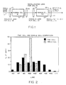
- the wavelength distribution obtained with the two-cell configuration is shown in FIG. 2, and includes a relatively broad and level distribution from the 532-nm pump wavelength through the fifth rotational Stokes line at 630 nm. Approximately 2.5% of the total output was measured in the sixth Stokes line at 655 nm and small amounts of the seventh Stokes and the first three anti-Stokes lines were also observed. An overall efficiency greater than 75% was maintained for conversion of the 532-nm pump energy into the various Raman lines.
- the two-cell configuration has, therefore, been shown to provide a much broader wavelength distribution than the single cell configuration, while still maintaining a high overall energy conversion efficiency.
- the two-cell converter of the preferred embodiment thus produces many higher order Stokes waves.
- pressure in the cells is much lower than for the vibrational MOPA configuration described above. Saturation because of a scarcity of molecules of the Raman medium becomes much more significant. Conversion to as many Stokes orders as possible is desired in the first cell 15.
- the second cell 23 is not used to amplify the input faithfully, but to obtain additional Stokes orders.
- the two-cell configuration has a clear and obvious advantage over the single cell approach, as shown by the data and figures presented.
- the two-cell configuration efficiently generates at least 10% conversion in the first five rotational Stokes orders.
- Neither the single cell nor the oscillator/amplifier design can duplicate this performance for the higher order Stokes lines.
- the single cell is limited to only the first three Stokes orders due to dielectric breakdown of the Raman medium and saturation of the number of molecules in the high intensity focal region.
- the MOPA configuration described above is limited to one line.
- the MOPA oscillator has the same limitations as a single cell device, i.e., the amplifier can only amplify the Stokes orders already generated in the oscillator, because the collimated geometry within the amplifier does not produce high enough intensities to exceed threshold.
- the invention has provided the efficient generation of two more rotational Raman orders than can be generated by either of the configurations used in the prior art. With optimization of the two-cell design, generation of additional orders beyond those already demonstrated may be expected.
- a Stokes wave grows according to Equation (1) above. Because the gain per unit length is proportional to the pump intensity, the distance taken to convert a pump wave to a Stokes wave is shorter where the pump beam intensity is high. In practice, the pump intensity varies with radial and longitudinal position in the beam. Because of the varying pump intensities in time and space, the output will be a combination of residual pump wavelength and several Stokes orders. Where the pump intensity is high, more conversion to higher Stokes orders will occur than in areas where the pump intensity is lower.
- the threshold intensity for SRS is usually so high that threshold is not readily obtained for collimated beams in gases. By focusing the beam into the cell with a lens, an intensity high enough to exceed threshold can be obtained near the focal point.
- the length of this high intensity region is often described by a term called the "confocal parameter.”
- the confocal parameter is defined as 2z o , where z o is a scale length for the beam known as the Rayleigh range.
- the conversion efficiency is a function of gain (which is a function of intensity) and interaction length (expressed by the confocal parameter).
- Shorter focal length results in a shorter confocal parameter, higher intensity within that region, and thus higher gain there.
- the increase in gain is just cancelled by the decrease in the length of the confocal parameter.
- Conversion efficiency does not depend upon focal length.
- long focal length results in large confocal parameters, so that the high gain region cannot be confined within a cell of reasonable length.
- the benefit of short focal length lenses is that cell length can be made small, but this does not increase the Raman conversion efficiency.
- the focal length must be sufficiently large to avoid optical breakdown of the gas, stimulated Brillouin scattering (SBS), or any one of the other competing nonlinear optical effects.
- SBS stimulated Brillouin scattering
- Two cells can be arranged in a folded configuration. To obtain more gain, more cells may be added. It is necessary to transfer the higher order Stokes waves into the second cell in order for them to seed the cell for even high order Stokes waves.
- optical dispersion or other means to modify the paths of the various Stokes orders to obtain further control of the conversion process.
Landscapes
- Physics & Mathematics (AREA)
- Electromagnetism (AREA)
- Engineering & Computer Science (AREA)
- Plasma & Fusion (AREA)
- Optics & Photonics (AREA)
- Nonlinear Science (AREA)
- Lasers (AREA)
- Optical Modulation, Optical Deflection, Nonlinear Optics, Optical Demodulation, Optical Logic Elements (AREA)
Description
- The subject invention relates to lasers and, more particularly, to a method and apparatus employing stimulated Raman scattering for obtaining a larger number of Stokes shifted waves from a laser pump than heretofore possible.
- Stimulated Raman scattering (SRS) was discovered at Hughes Aircraft Company in 1962. Until about 10 years ago, SRS was of scientific importance and was used as a tool for various spectroscopic tasks, but was not generally applied to the generation of new laser lines with substantial energy or power. At Hughes, use of Raman conversion was finally made for a laser cloud height indicator, and later for an eyesafe rangefinder (MELIOS). These systems used methane (CH₄) as a vibrational Raman medium. The ordinary Nd:YAG line at 1.064 microns was shifted to 1.54 microns, which was considered eyesafe at the energy produced. Other commonly used Raman media are hydrogen (H₂) and deuterium (D₂).
- For some applications, stimulated rotational Raman scattering (SRRS) has been considered more desirable than vibrational SRS. The rotational excitation of most molecules is of much lower energy than the vibrational excitation, and thus produces a smaller wavelength shift. Some prior art Stokes wave generators have used a single cell employing stimulated rotational Raman scattering (SRRS) to convert the pump wavelength into a series of longer wavelengths. Such prior art approaches to generation of Stokes shifted waves have typically exhibited two, or possibly three, Stokes lines in the output. Attempts to obtain more orders by increasing the intensity in such single cell systems failed because of optical breakdown of the Raman medium.
- Another device which has been used to generate Stokes shifted waves is an oscillator-amplifier configuration or master oscillator power amplifier (MOPA). Such an amplifier employs two cells. In a MOPA, a small portion of the pump is diverted into an oscillator cell, where a seed is created to drive an amplifier cell. Low power levels within the oscillator provide good seed beam quality. The seed from the oscillator is combined with the remainder of the pump energy inside the amplifier, where the stimulated emission process provides amplification of the seed, generating a high power Raman shifted output with good beam quality. Other experimenters have used this configuration to achieve high conversion efficiency into a single Stokes line. However, the configuration has not generated a large number of Stokes shifted waves.
- Accordingly, it is the object of the invention to provide an improved Raman converter to generate a plurality of Stokes lines.
- This object is solved by a Raman converter having the features of
claim 1. - The invention comprises two or more cells wherein a laser pump wave is converted into radiation of longer wavelengths by stimulated Raman scattering (SRS). The output of the first cell, including any residual pump and Stokes components, is passed into a similar second cell. Each Stokes wave acts as a pump for the next higher order Stokes wave. Pressures in the two cells are optimized to achieve maximum conversion of pump energy into Stokes lines. The invention uses stimulated rotational Raman scattering (SRRS) with cell pressures optimized for maximum rotational Stokes gain.
- The invention produces a larger number of Stokes shifted waves from a laser pump than is possible from a single cell. A large number of Stokes shifted waves is obtained because the multiple cell concept increases the Raman gain length and provides a "seed" for the process in cells following the first.
-
- FIG. 1 is a block schematic diagram of the preferred embodiment of the invention; and
- FIG. 2 is a graph illustrative of the operation of the preferred embodiment.
- The following description is provided to enable any person skilled in the art to make and use the invention and sets forth the best modes contemplated by the inventors of carrying out their invention. Various modifications, however, will remain readily apparent to those skilled in the art, since the generic principles of the present invention have been defined herein specifically to provide a Raman converter system optimized to generate a relatively large number of rotational Stokes shifted waves.
- According to the basic principle of stimulated Raman scattering, photons with wavelength λ₁ excite a material which will then emit a photon at a longer wavelength λ₂, while leaving energy in the material in the form of heat. The difference between the wavelengths λ₁ and λ₂ is characteristic of the material. Energy of wavelength λ₁ is referred to as the pump, while wavelength λ₂ is the first Stokes line. Energy of wavelength λ₂ can undergo a similar transition to generate wavelength λ₃, the second Stokes line, and so on, to higher order Stokes lines. The intensity of the Stokes wavelength produced is given by:

where: - Is
- = intensity of Stokes line produced
- Iso
- = initial intensity of Stokes line
- gs
- = Raman gain
- Ip
- = intensity of line pumping that Stokes order
- Z
- = gain length
- FIG. 1 illustrates a system including first and second Raman
cells lenses lens 13, and the focused beam is supplied to the first Ramancell 15. Theoutput 17 of the first Ramancell 15 is recollimated by a first recollimatinglens 19, whose output is focused by a second focusinglens 21 and supplied to thesecond Raman cell 23. Theoutput 25 of thesecond Raman cell 23 is supplied to the second recollimatinglens 27, which recollimates the light into the final rotational Raman output. - According to the invention, each Raman
cell first cell 15 provide a higher initial Stokes intensity, Iso, in thesecond cell 23, and thesecond cell 23 provides additional gain length, z. - In the invention, the Raman medium in each of the first and
second Raman cells - In order to achieve maximum conversion into the rotational lines, while avoiding any significant generation of unwanted vibrational lines, the pressure in each
Raman cell - According to the invention, the optimized pressures are 0.69x10⁵ Pa (10 pounds per square inch gauge) (psig) H₂ for the
first Raman cell 15 and 1.38x10⁵ Pa (20 psig) H₂ for thesecond Raman cell 23. - In the same implementation, the pump beam 11 is a 532-nanometer (nm) laser beam produced by a phase conjugated, frequency doubled Nd:YAG laser, as known in the art. The pump 11 is preferably generated by a MOPA configuration and is circularly polarized so as not to excite vibrational SRS. The input pump energy is approximately 230 milliJoules (mJ) with a beam diameter of 6 millimeters, divergence of 0.6 milliradians, and a pulsewidth of 25 nanoseconds full width at the half maximum. The
first lens 13 has a focal length of +50 centimeters and focuses the input pump beam 11 to generate an approximate intensity (Ip) of 13 Gigawatts/centimeter² (GW/cm²) within thefirst Raman cell 15. Thesecond lens 19 has a focal length of +50 centimeters and recollimates the output of thefirst cell 15. This output consists of approximately:
Thethird lens 21 has a focal length of +50 centimeters and focuses the radiation into thesecond Raman cell 23, generating initial Stokes intensities (Iso) within thesecond Raman cell 23 of:
The output of thesecond cell 23 is recollimated into the final output by thefourth lens 27, which has a focal length of +50 centimeters. - In operation, the output of the
first cell 15 consists of 30-40% conversion into the first two rotational Stokes lines and approximately 10% conversion into the third Stokes line. Small amounts of the fourth and fifth rotational Stokes lines and the first vibrational Stokes line are also present. - As noted above, the use of the
second cell 23 provides additional gain length which avoids saturation and allows the generation of the higher order Stokes lines. The output of thefirst cell 15 acts as a seed for the generation of the higher order Raman lines in thesecond cell 23. The wavelength distribution obtained with the two-cell configuration is shown in FIG. 2, and includes a relatively broad and level distribution from the 532-nm pump wavelength through the fifth rotational Stokes line at 630 nm. Approximately 2.5% of the total output was measured in the sixth Stokes line at 655 nm and small amounts of the seventh Stokes and the first three anti-Stokes lines were also observed. An overall efficiency greater than 75% was maintained for conversion of the 532-nm pump energy into the various Raman lines. The two-cell configuration has, therefore, been shown to provide a much broader wavelength distribution than the single cell configuration, while still maintaining a high overall energy conversion efficiency. - For both single and double cell configurations, conversion efficiency to higher Stokes orders depends upon the pump laser characteristics and upon the geometry used to focus the pump into the Raman cell(s). In comparing exemplary single cell and double cell performance, the laser and focusing characteristics were the same in both cases:
Input energy - 230 mJ
Pump beam divergence - 0.6 mrad
Focusing configuration - F/80 (50 cm focal length, 0.6 cm beam diameter)
The conversion to Stokes orders (and energy remaining in the residual pump) are expressed in terms of percentage of the input energy. (For example, if a 100 mJ pump produced 10 mJ of a Stokes line, the conversion efficiency of that line is 10%.) Typical conversion efficiencies for the single cell and double cell configurations are shown below and are graphed in FIG. 2.
- The two-cell converter of the preferred embodiment thus produces many higher order Stokes waves. For rotational Raman conversion, pressure in the cells is much lower than for the vibrational MOPA configuration described above. Saturation because of a scarcity of molecules of the Raman medium becomes much more significant. Conversion to as many Stokes orders as possible is desired in the
first cell 15. Thesecond cell 23 is not used to amplify the input faithfully, but to obtain additional Stokes orders. - The two-cell configuration has a clear and obvious advantage over the single cell approach, as shown by the data and figures presented. The two-cell configuration efficiently generates at least 10% conversion in the first five rotational Stokes orders. Neither the single cell nor the oscillator/amplifier design can duplicate this performance for the higher order Stokes lines. The single cell is limited to only the first three Stokes orders due to dielectric breakdown of the Raman medium and saturation of the number of molecules in the high intensity focal region.
- The MOPA configuration described above is limited to one line. The MOPA oscillator has the same limitations as a single cell device, i.e., the amplifier can only amplify the Stokes orders already generated in the oscillator, because the collimated geometry within the amplifier does not produce high enough intensities to exceed threshold.
- Therefore, the invention has provided the efficient generation of two more rotational Raman orders than can be generated by either of the configurations used in the prior art. With optimization of the two-cell design, generation of additional orders beyond those already demonstrated may be expected.
- For constant pump intensity and low Stokes intensity, a Stokes wave grows according to Equation (1) above. Because the gain per unit length is proportional to the pump intensity, the distance taken to convert a pump wave to a Stokes wave is shorter where the pump beam intensity is high. In practice, the pump intensity varies with radial and longitudinal position in the beam. Because of the varying pump intensities in time and space, the output will be a combination of residual pump wavelength and several Stokes orders. Where the pump intensity is high, more conversion to higher Stokes orders will occur than in areas where the pump intensity is lower.
- The threshold intensity for SRS is usually so high that threshold is not readily obtained for collimated beams in gases. By focusing the beam into the cell with a lens, an intensity high enough to exceed threshold can be obtained near the focal point. The length of this high intensity region is often described by a term called the "confocal parameter." The confocal parameter is defined as 2zo, where zo is a scale length for the beam known as the Rayleigh range. The Rayleigh length can be calculated using

where wo is the radius of the beam waist and λ is the wavelength of the radiation. The conversion efficiency is a function of gain (which is a function of intensity) and interaction length (expressed by the confocal parameter). Shorter focal length results in a shorter confocal parameter, higher intensity within that region, and thus higher gain there. However, the increase in gain is just cancelled by the decrease in the length of the confocal parameter. Conversion efficiency, in principle, does not depend upon focal length. However, in practice, long focal length results in large confocal parameters, so that the high gain region cannot be confined within a cell of reasonable length. The benefit of short focal length lenses is that cell length can be made small, but this does not increase the Raman conversion efficiency. The focal length, however, must be sufficiently large to avoid optical breakdown of the gas, stimulated Brillouin scattering (SBS), or any one of the other competing nonlinear optical effects. - Using two cells according to the preferred embodiment allows intensity to be reduced to where there is no gas breakdown. Two or more cells can be arranged in a folded configuration. To obtain more gain, more cells may be added. It is necessary to transfer the higher order Stokes waves into the second cell in order for them to seed the cell for even high order Stokes waves. Although not currently implemented, it may be possible to use optical dispersion or other means to modify the paths of the various Stokes orders to obtain further control of the conversion process.
- It is to be understood that, within the scope of the appended claims, the invention may be practiced other than as specifically described herein.
This equation holds for each Stokes order.
Claims (8)
- A Raman converter for generating a light output, including the first, second, third, fourth, fifth, and sixth Stokes lines from a pump beam (11) by stimulated rotational Raman scattering, comprising:
a first Raman cell means (13,15) for receiving the pump beam (11) and producing a first output (17), said first Raman cell means (13,15) containing a first Raman medium of H₂ at a first optimized low pressure at 0.69 x 10⁵Pa (10psig) H₂; and
a second Raman cell means (19,21,23) for receiving said first output beam (17) and producing a second output (25), said second Raman cell means (19,21,23) containing a second Raman medium of H₂ at a second optimized low pressure of 1.38 x 10⁵ Pa (20 psig) H₂. - The Raman converter of claim 1, wherein said first Raman cell means (13,15) comprises:
a Raman cell (15); and
a focusing lens means (13) for focusing said pump beam (11) into said first Raman cell (15). - The Raman converter of claim 2, wherein said second Raman cell means (19,21,23) comprises:
a second Raman cell (23);
means (19) for recollimating said first output (17) to produce a recollimated beam; and
means (21) for focusing said recollimated beam into said second Raman cell (23). - The Raman converter of claim 3, wherein said second Raman cell means further comprises means (27) for recollimating said second output (25).
- The Raman converter of claim 4, wherein the output (17) of said first Raman cell (15) includes the pump wavelength and first, second and third Stokes lines.
- The Raman converter of claim 5, wherein the output (25) of said second cell (23) includes the first, second, and third Stokes lines and fourth, fifth, and sixth Stokes lines.
- The Raman converter of claim 1, wherein said pump beam (11) is a circularly polarized beam generated by a master oscillator power amplifier configuration.
- Laser apparatus comprising a Raman converter according to any one of claims 1 to 7; and including
means for generating a laser pump beam having a first wavelength.
Applications Claiming Priority (2)
| Application Number | Priority Date | Filing Date | Title |
|---|---|---|---|
| US484340 | 1983-04-12 | ||
| US48434090A | 1990-02-26 | 1990-02-26 |
Publications (3)
| Publication Number | Publication Date |
|---|---|
| EP0444435A2 EP0444435A2 (en) | 1991-09-04 |
| EP0444435A3 EP0444435A3 (en) | 1992-05-06 |
| EP0444435B1 true EP0444435B1 (en) | 1995-04-19 |
Family
ID=23923747
Family Applications (1)
| Application Number | Title | Priority Date | Filing Date |
|---|---|---|---|
| EP91101465A Expired - Lifetime EP0444435B1 (en) | 1990-02-26 | 1991-02-04 | Two cell laser raman converter |
Country Status (8)
| Country | Link |
|---|---|
| EP (1) | EP0444435B1 (en) |
| JP (1) | JP2716277B2 (en) |
| KR (1) | KR940010000B1 (en) |
| DE (1) | DE69108961T2 (en) |
| ES (1) | ES2072461T3 (en) |
| IL (1) | IL97167A (en) |
| NO (1) | NO910601L (en) |
| TR (1) | TR26759A (en) |
Cited By (1)
| Publication number | Priority date | Publication date | Assignee | Title |
|---|---|---|---|---|
| CN100487623C (en) * | 2005-10-10 | 2009-05-13 | 中国科学院安徽光学精密机械研究所 | Closed double crystal adjustable temperature controlling box |
Families Citing this family (6)
| Publication number | Priority date | Publication date | Assignee | Title |
|---|---|---|---|---|
| GB9115556D0 (en) * | 1991-07-18 | 1991-11-06 | Gec Ferranti Defence Syst | A raman laser |
| CN100487433C (en) * | 2005-06-07 | 2009-05-13 | 中国科学院安徽光学精密机械研究所 | Vehicular pollution-motoring lidar device based on Raman light source |
| US8089998B2 (en) | 2009-05-26 | 2012-01-03 | High Q Technologies Gmbh | Ultra-short pulse laser system and method for producing femtosecond or picosecond pulses |
| EP2256879B1 (en) * | 2009-05-26 | 2013-10-02 | High Q Laser GmbH | Ultrashort pulse laser system and method for creating femtosecond or picosecond pulses |
| CN101902010B (en) * | 2009-05-26 | 2013-07-17 | 高质激光有限公司 | Ultrashort pulse laser system and method for creating femtosecond or picosecond pulses |
| CN112186494A (en) * | 2019-07-04 | 2021-01-05 | 中国科学院大连化学物理研究所 | CO (carbon monoxide)2Cascade ultraviolet Raman laser |
Family Cites Families (1)
| Publication number | Priority date | Publication date | Assignee | Title |
|---|---|---|---|---|
| JPH0732295B2 (en) * | 1988-04-30 | 1995-04-10 | 信彦 石橋 | Tunable laser source |
-
1991
- 1991-02-04 DE DE69108961T patent/DE69108961T2/en not_active Expired - Fee Related
- 1991-02-04 EP EP91101465A patent/EP0444435B1/en not_active Expired - Lifetime
- 1991-02-04 ES ES91101465T patent/ES2072461T3/en not_active Expired - Lifetime
- 1991-02-06 IL IL97167A patent/IL97167A/en not_active IP Right Cessation
- 1991-02-12 TR TR91/0135A patent/TR26759A/en unknown
- 1991-02-14 NO NO91910601A patent/NO910601L/en unknown
- 1991-02-25 KR KR1019910003027A patent/KR940010000B1/en not_active Expired - Fee Related
- 1991-02-26 JP JP3031010A patent/JP2716277B2/en not_active Expired - Lifetime
Cited By (1)
| Publication number | Priority date | Publication date | Assignee | Title |
|---|---|---|---|---|
| CN100487623C (en) * | 2005-10-10 | 2009-05-13 | 中国科学院安徽光学精密机械研究所 | Closed double crystal adjustable temperature controlling box |
Also Published As
| Publication number | Publication date |
|---|---|
| EP0444435A3 (en) | 1992-05-06 |
| KR920000159A (en) | 1992-01-10 |
| JPH04215491A (en) | 1992-08-06 |
| DE69108961T2 (en) | 1995-08-24 |
| JP2716277B2 (en) | 1998-02-18 |
| EP0444435A2 (en) | 1991-09-04 |
| NO910601D0 (en) | 1991-02-14 |
| NO910601L (en) | 1991-08-27 |
| KR940010000B1 (en) | 2020-03-26 |
| IL97167A0 (en) | 1992-05-25 |
| TR26759A (en) | 1995-05-15 |
| ES2072461T3 (en) | 1995-07-16 |
| IL97167A (en) | 1993-05-13 |
| DE69108961D1 (en) | 1995-05-24 |
Similar Documents
| Publication | Publication Date | Title |
|---|---|---|
| US5062112A (en) | Two cell laser raman converter | |
| Polyanskiy et al. | Demonstration of a 2 ps, 5 TW peak power, long-wave infrared laser based on chirped-pulse amplification with mixed-isotope CO2 amplifiers | |
| Sullivan et al. | Multiterawatt, 100-fs laser | |
| Siebold et al. | Terawatt diode-pumped Yb: Ca F 2 laser | |
| Schwarzenbach et al. | Subpicosecond KrF* excimer-laser source | |
| US20020131164A1 (en) | High average power chirped pulse fiber amplifier array | |
| Matousek et al. | Design of a multi-petawatt optical parametric chirped pulse amplifier for the iodine laser ASTERIX IV | |
| Thurow et al. | Third-generation megahertz-rate pulse burst laser system | |
| US4641312A (en) | Method and device for producing individual short laser pulses | |
| Golinelli et al. | CEP-stabilized, sub-18 fs, 10 kHz and TW-class 1 kHz dual output Ti: Sa laser with wavelength tunability option | |
| EP0444435B1 (en) | Two cell laser raman converter | |
| Nees et al. | Ensuring compactness, reliability, and scalability for the next generation of high-field lasers | |
| Eimerl et al. | Large bandwidth frequency-converted Nd: glass laser at 527 nm with Δν/ν= 2% | |
| US20220239055A1 (en) | Multiple coherent wavelength optical sources | |
| Duering et al. | Generation of tuneable 589nm radiation as a Na guide star source using an optical parametric amplifier | |
| Trainor et al. | Stimulated Raman scattering of XeF* laser radiation in H 2 | |
| Mannik et al. | Tunable infrared generation using third Stokes output from a waveguide Raman shifter | |
| EP3014352A1 (en) | Method and system for linearizing non-linear optics | |
| Stark et al. | 100 fs pulses directly from a kW-class mJ-level ytterbium-doped fiber CPA laser system | |
| Crump et al. | Diode pumps for future laser plasma accelerators: Perspectives from research and industry | |
| JPWO2017222022A1 (en) | Fiber laser circuit | |
| Frey et al. | Tunable infrared generation by stimulated Raman scattering | |
| Kinyaevskiy et al. | Stimulated Raman scattering of a broadband chirped Ti: sapphire laser pulse in calcite seeded by a narrowband nanosecond Nd: YAG laser pulse | |
| Heinrichs et al. | Design, Development and Utilization of the New LLNL Inherently Safe Subcritical Assembly (ISSA) | |
| Szatmári et al. | 3 Femtosecond excimer lasers and their applications: 3 Gas lasers |
Legal Events
| Date | Code | Title | Description |
|---|---|---|---|
| PUAI | Public reference made under article 153(3) epc to a published international application that has entered the european phase |
Free format text: ORIGINAL CODE: 0009012 |
|
| AK | Designated contracting states |
Kind code of ref document: A2 Designated state(s): BE CH DE ES FR GB GR IT LI NL SE |
|
| PUAL | Search report despatched |
Free format text: ORIGINAL CODE: 0009013 |
|
| AK | Designated contracting states |
Kind code of ref document: A3 Designated state(s): BE CH DE ES FR GB GR IT LI NL SE |
|
| 17P | Request for examination filed |
Effective date: 19921104 |
|
| 17Q | First examination report despatched |
Effective date: 19931116 |
|
| GRAA | (expected) grant |
Free format text: ORIGINAL CODE: 0009210 |
|
| AK | Designated contracting states |
Kind code of ref document: B1 Designated state(s): BE CH DE ES FR GB GR IT LI NL SE |
|
| REF | Corresponds to: |
Ref document number: 69108961 Country of ref document: DE Date of ref document: 19950524 |
|
| REG | Reference to a national code |
Ref country code: ES Ref legal event code: FG2A Ref document number: 2072461 Country of ref document: ES Kind code of ref document: T3 |
|
| ITF | It: translation for a ep patent filed | ||
| ET | Fr: translation filed | ||
| REG | Reference to a national code |
Ref country code: GR Ref legal event code: FG4A Free format text: 3016865 |
|
| PLBE | No opposition filed within time limit |
Free format text: ORIGINAL CODE: 0009261 |
|
| STAA | Information on the status of an ep patent application or granted ep patent |
Free format text: STATUS: NO OPPOSITION FILED WITHIN TIME LIMIT |
|
| 26N | No opposition filed | ||
| REG | Reference to a national code |
Ref country code: GB Ref legal event code: 732E |
|
| NLS | Nl: assignments of ep-patents |
Owner name: RAYTHEON COMPANY;HE HOLDINGS, INC. |
|
| REG | Reference to a national code |
Ref country code: ES Ref legal event code: PC2A |
|
| REG | Reference to a national code |
Ref country code: FR Ref legal event code: TP Ref country code: FR Ref legal event code: CD Ref country code: FR Ref legal event code: CA |
|
| REG | Reference to a national code |
Ref country code: GB Ref legal event code: IF02 |
|
| PGFP | Annual fee paid to national office [announced via postgrant information from national office to epo] |
Ref country code: FR Payment date: 20020114 Year of fee payment: 12 |
|
| PGFP | Annual fee paid to national office [announced via postgrant information from national office to epo] |
Ref country code: GB Payment date: 20020117 Year of fee payment: 12 |
|
| PGFP | Annual fee paid to national office [announced via postgrant information from national office to epo] |
Ref country code: CH Payment date: 20020118 Year of fee payment: 12 |
|
| PGFP | Annual fee paid to national office [announced via postgrant information from national office to epo] |
Ref country code: NL Payment date: 20020121 Year of fee payment: 12 Ref country code: DE Payment date: 20020121 Year of fee payment: 12 |
|
| PGFP | Annual fee paid to national office [announced via postgrant information from national office to epo] |
Ref country code: SE Payment date: 20020122 Year of fee payment: 12 |
|
| PGFP | Annual fee paid to national office [announced via postgrant information from national office to epo] |
Ref country code: GR Payment date: 20020124 Year of fee payment: 12 |
|
| PGFP | Annual fee paid to national office [announced via postgrant information from national office to epo] |
Ref country code: ES Payment date: 20020205 Year of fee payment: 12 |
|
| PGFP | Annual fee paid to national office [announced via postgrant information from national office to epo] |
Ref country code: BE Payment date: 20020213 Year of fee payment: 12 |
|
| PG25 | Lapsed in a contracting state [announced via postgrant information from national office to epo] |
Ref country code: GB Free format text: LAPSE BECAUSE OF NON-PAYMENT OF DUE FEES Effective date: 20030204 |
|
| PG25 | Lapsed in a contracting state [announced via postgrant information from national office to epo] |
Ref country code: SE Free format text: LAPSE BECAUSE OF NON-PAYMENT OF DUE FEES Effective date: 20030205 Ref country code: ES Free format text: LAPSE BECAUSE OF NON-PAYMENT OF DUE FEES Effective date: 20030205 |
|
| PG25 | Lapsed in a contracting state [announced via postgrant information from national office to epo] |
Ref country code: LI Free format text: LAPSE BECAUSE OF NON-PAYMENT OF DUE FEES Effective date: 20030228 Ref country code: CH Free format text: LAPSE BECAUSE OF NON-PAYMENT OF DUE FEES Effective date: 20030228 Ref country code: BE Free format text: LAPSE BECAUSE OF NON-PAYMENT OF DUE FEES Effective date: 20030228 |
|
| PG25 | Lapsed in a contracting state [announced via postgrant information from national office to epo] |
Ref country code: NL Free format text: LAPSE BECAUSE OF NON-PAYMENT OF DUE FEES Effective date: 20030901 |
|
| PG25 | Lapsed in a contracting state [announced via postgrant information from national office to epo] |
Ref country code: DE Free format text: LAPSE BECAUSE OF NON-PAYMENT OF DUE FEES Effective date: 20030902 |
|
| PG25 | Lapsed in a contracting state [announced via postgrant information from national office to epo] |
Ref country code: GR Free format text: LAPSE BECAUSE OF NON-PAYMENT OF DUE FEES Effective date: 20030904 |
|
| GBPC | Gb: european patent ceased through non-payment of renewal fee | ||
| EUG | Se: european patent has lapsed | ||
| REG | Reference to a national code |
Ref country code: CH Ref legal event code: PL |
|
| PG25 | Lapsed in a contracting state [announced via postgrant information from national office to epo] |
Ref country code: FR Free format text: LAPSE BECAUSE OF NON-PAYMENT OF DUE FEES Effective date: 20031031 |
|
| NLV4 | Nl: lapsed or anulled due to non-payment of the annual fee |
Effective date: 20030901 |
|
| REG | Reference to a national code |
Ref country code: FR Ref legal event code: ST |
|
| REG | Reference to a national code |
Ref country code: ES Ref legal event code: FD2A Effective date: 20030205 |
|
| PG25 | Lapsed in a contracting state [announced via postgrant information from national office to epo] |
Ref country code: IT Free format text: LAPSE BECAUSE OF NON-PAYMENT OF DUE FEES;WARNING: LAPSES OF ITALIAN PATENTS WITH EFFECTIVE DATE BEFORE 2007 MAY HAVE OCCURRED AT ANY TIME BEFORE 2007. THE CORRECT EFFECTIVE DATE MAY BE DIFFERENT FROM THE ONE RECORDED. Effective date: 20050204 |