EP0444434A2 - Portable counter-flow helium leak detector for testing a vessel provided with its own pumping group - Google Patents
Portable counter-flow helium leak detector for testing a vessel provided with its own pumping group Download PDFInfo
- Publication number
- EP0444434A2 EP0444434A2 EP91101458A EP91101458A EP0444434A2 EP 0444434 A2 EP0444434 A2 EP 0444434A2 EP 91101458 A EP91101458 A EP 91101458A EP 91101458 A EP91101458 A EP 91101458A EP 0444434 A2 EP0444434 A2 EP 0444434A2
- Authority
- EP
- European Patent Office
- Prior art keywords
- pump
- detector
- inlet valve
- gauge
- vacuum pump
- Prior art date
- Legal status (The legal status is an assumption and is not a legal conclusion. Google has not performed a legal analysis and makes no representation as to the accuracy of the status listed.)
- Granted
Links
- 239000001307 helium Substances 0.000 title claims abstract description 8
- 229910052734 helium Inorganic materials 0.000 title claims abstract description 8
- SWQJXJOGLNCZEY-UHFFFAOYSA-N helium atom Chemical compound [He] SWQJXJOGLNCZEY-UHFFFAOYSA-N 0.000 title claims abstract description 8
- 238000005086 pumping Methods 0.000 title claims abstract description 7
- 239000007789 gas Substances 0.000 claims abstract description 12
- 238000009434 installation Methods 0.000 claims abstract description 6
- 238000009530 blood pressure measurement Methods 0.000 claims description 5
- 238000005259 measurement Methods 0.000 claims description 2
- 238000010586 diagram Methods 0.000 description 5
- 238000009792 diffusion process Methods 0.000 description 2
- 230000004913 activation Effects 0.000 description 1
- XAGFODPZIPBFFR-UHFFFAOYSA-N aluminium Chemical compound [Al] XAGFODPZIPBFFR-UHFFFAOYSA-N 0.000 description 1
- 229910052782 aluminium Inorganic materials 0.000 description 1
- 238000002513 implantation Methods 0.000 description 1
- 238000004806 packaging method and process Methods 0.000 description 1
- BASFCYQUMIYNBI-UHFFFAOYSA-N platinum Chemical compound [Pt] BASFCYQUMIYNBI-UHFFFAOYSA-N 0.000 description 1
- 230000011664 signaling Effects 0.000 description 1
Images


Classifications
-
- G—PHYSICS
- G01—MEASURING; TESTING
- G01M—TESTING STATIC OR DYNAMIC BALANCE OF MACHINES OR STRUCTURES; TESTING OF STRUCTURES OR APPARATUS, NOT OTHERWISE PROVIDED FOR
- G01M3/00—Investigating fluid-tightness of structures
- G01M3/02—Investigating fluid-tightness of structures by using fluid or vacuum
- G01M3/04—Investigating fluid-tightness of structures by using fluid or vacuum by detecting the presence of fluid at the leakage point
- G01M3/20—Investigating fluid-tightness of structures by using fluid or vacuum by detecting the presence of fluid at the leakage point using special tracer materials, e.g. dye, fluorescent material, radioactive material
- G01M3/202—Investigating fluid-tightness of structures by using fluid or vacuum by detecting the presence of fluid at the leakage point using special tracer materials, e.g. dye, fluorescent material, radioactive material using mass spectrometer detection systems
-
- G—PHYSICS
- G01—MEASURING; TESTING
- G01M—TESTING STATIC OR DYNAMIC BALANCE OF MACHINES OR STRUCTURES; TESTING OF STRUCTURES OR APPARATUS, NOT OTHERWISE PROVIDED FOR
- G01M3/00—Investigating fluid-tightness of structures
- G01M3/02—Investigating fluid-tightness of structures by using fluid or vacuum
- G01M3/04—Investigating fluid-tightness of structures by using fluid or vacuum by detecting the presence of fluid at the leakage point
- G01M3/20—Investigating fluid-tightness of structures by using fluid or vacuum by detecting the presence of fluid at the leakage point using special tracer materials, e.g. dye, fluorescent material, radioactive material
- G01M3/22—Investigating fluid-tightness of structures by using fluid or vacuum by detecting the presence of fluid at the leakage point using special tracer materials, e.g. dye, fluorescent material, radioactive material for pipes, cables or tubes; for pipe joints or seals; for valves; for welds; for containers, e.g. radiators
- G01M3/226—Investigating fluid-tightness of structures by using fluid or vacuum by detecting the presence of fluid at the leakage point using special tracer materials, e.g. dye, fluorescent material, radioactive material for pipes, cables or tubes; for pipe joints or seals; for valves; for welds; for containers, e.g. radiators for containers, e.g. radiators
Definitions
- the present invention relates to a portable helium leak detector operating against the current comprising only one pump, said pump being a secondary vacuum pump having an inlet and an outlet, a gas analyzer being connected to the inlet of said pump, said outlet being connected, via an inlet valve, to a connection orifice to an installation to be tested, said installation being under vacuum or being able to be connected to primary pumping means, the detector comprising in addition electronic supply and control circuits, power-up means and display means.
- the present invention aims to provide a detector of the previous type having a more stable helium signal, extremely safe and simple handling, excluding any possibility of false operation and therefore can be used even by unqualified people and allowing to win the time between two successive leak tests.
- the subject of the invention is therefore a leak detector as defined above, characterized in that it comprises a first pressure measurement gauge situated between said inlet valve and said connection orifice, a control lever for activation of the detector, said control circuits ensuring the opening of said inlet valve and the start-up of said secondary vacuum pump if, with the detector energized, said control handle has been actuated and when the pressure measured by said gauge has dropped below a determined value, the gas analyzer being started automatically when said secondary vacuum pump has reaches its nominal speed, and in that it further comprises a second pressure measurement gauge located at the level of said vacuum pump, means being provided so that, with the detector energized, positioning rest of said control lever causes said inlet valve to close if the latter is open, while maintaining the supply to said pump if the pressure measured by said second measurement gauge is less than a set value, the gas analyzer also being kept in operating condition if said pump is at its nominal speed, the latter being a rotary mechanical pump.
- the whole detector is contained in a single suitcase provided with manual means of transport.
- It includes a single pump 1 which is a turbomolecular secondary pump and a gas analyzer 2 connected to the inlet 3 of the pump.
- the outlet 4 of the pump is connected to a connection orifice forming a flange 5 by means of an inlet valve 6.
- the inlet valve 6 is an electromagnetic valve controlled by means of a first pressure measurement gauge 7 disposed between the inlet valve and the flange 5. It is for example a Pirani type thermal gauge .
- the detector also comprises a second gauge 8 for measuring pressure located at the level of the vacuum pump 1 and of the same type as the first gauge 7, and a third gauge 9, of the triode gauge type, at the gas analyzer level 2.
- the detector is intended to be connected to an enclosure to be tested 10 which is already under vacuum or which can be connected to primary pumping means 11.
- the enclosure 10 has a connection valve 12.
- the detector operates in the said mode "against a current".
- a power transformer 15 Inside the case are also located all the accessories necessary for the operation of the detector and in particular a power transformer 15, a printed circuit board 16 for the electronic power circuits of the pump 8, as well as a printed circuit board 17 for the electronic control, automation and signaling circuits and a control board 18 (FIG. 4) comprising display dials.
- the assembly is fixed to an aluminum cradle 19 which includes an upper plate 20 which includes the control plate 18.
- the control plate 18 comprises, in addition to control and display elements, a control lever 21 for switching on the detector.
- the transformer 15 includes a power cord, not shown, for its connection to the sector ensuring the energization of the detector.
- the electronic circuits of the printed circuit board 17 comprise inter alia a logic control circuit such as that shown in FIG. 5.
- This circuit includes an "OR" gate 22, the output of which controls the starting of the pump 1 and which comprises three inputs 23, 24 and 25 coming respectively from the output of three "AND" gates 26, 27 and 28.
- the "AND" gate 26 has two inputs 29 and 30.
- the input 29 receives a signal, on line 31, when the control lever 21 is actuated and the input 30 receives, via line 40, a signal when the pressure, measured by the first gauge 7 is less than a determined value, of 10 mbar in the case of the example cited.
- the "AND" door 27 also has two inputs 32 and 33.
- the input 32 is connected to line 31 by an inverter 34 and therefore receives a signal when the control lever 21 is in the rest position, not actuated.
- the input 33 is connected to a line 35 which receives a signal when the pressure indicated by the second gauge 8 is less than a set value, of 5.10 ⁇ 2 mbar in the case of the example.
- the "AND" gate 28 has three inputs 36, 37 and 38.
- Input 36 is connected to line 35, input 37 to line 31 and input 38 to line 40 but via an inverter 39.
- the logic circuit further comprises an "AND” gate 41 whose output 42 controls, by means of a time delay 43, the opening of the inlet valve 6.
- This "AND” gate 41 has two inputs 44 and 45; input 44 being connected to line 40 and input 45 to line 31.
- the pump l starts automatically and the inlet valve 6 opens if the control handle 21 is actuated and if the pressure indicated by the first gauge 7 drops below the value determined by 10 mbar.
- the gas analyzer (mass spectrometer 2) is started up automatically as soon as the turbomolecular pump 1 reaches its nominal speed, 27000 rpm in the example, as shown in line 46 of the logic shown in Figure 5.
- the timer 43 includes an inhibit input 47 which is connected to line 46.
- the detector can be kept in working order, provided that it is nevertheless powered, after having carried out a test.
- the control lever 21 is placed in the rest position, the inlet valve 6 closes since the inlet 45 of the "AND" gate 41 is no longer supplied but the pump 1 is always supplied because the "OR" gate 22 then remains activated by its input 24 and in addition the mass spectrometer 2 is still in working condition because the pump 1 is still operating at its nominal speed.
- FIG. 6 gives a complete functional logic diagram of the various stages of operation of the apparatus.
- the suitcase 13 has a fan 53 for ventilating the electronic circuits and the solenoid valve 6. At 54, we see the preamplifier of the mass spectrometer and at 55 the magnet.
- the suitcase has a handle 56 and a carrying strap 57.
- the detector of the invention included in a suitcase has many advantages: thanks to its transportability, its low weight, of the order of 18 kg, its robustness, it accompanies the convenience store in its movements whatever the mode of transport. This is completely new: the convenience store arrives on the site with its device.
- this detector can fulfill, in addition to its usual role of tightness control, an emergency repair function if necessary.
Abstract
Description
La présente invention concerne un détecteur de fuite portable à hélium fonctionnant en contre-courant ne comprenant qu'une seule pompe, ladite pompe étant une pompe à vide secondaire comportant une entrée et une sortie, un analyseur de gaz étant branché à l'entrée de ladite pompe, ladite sortie étant reliée, par l'intermédiaire d'une vanne d'entrée, à un orifice de raccordement à une installation à tester, ladite installation étant sous vide ou pouvant être raccordée à des moyens de pompage primaire, le détecteur comportant en outre des circuits électroniques d'alimentation et de commande, des moyens de mise sous tension et des moyens d'affichage.The present invention relates to a portable helium leak detector operating against the current comprising only one pump, said pump being a secondary vacuum pump having an inlet and an outlet, a gas analyzer being connected to the inlet of said pump, said outlet being connected, via an inlet valve, to a connection orifice to an installation to be tested, said installation being under vacuum or being able to be connected to primary pumping means, the detector comprising in addition electronic supply and control circuits, power-up means and display means.
On connaît par la notice "Porta test", datée du 14 mars 1975 de la société Varian (détecteur de fuites à hélium Porta-test Ref. 0925K0777-301) un tel détecteur dans lequel la pompe à vide secondaire est une pompe à diffusion moléculaire. Dans le mode de fonctionnement à contre-courant d'un tel détecteur, la pompe à diffusion doit fonctionner en régime de sous-chauffe pour permettre le passage à contre-courant de l'hélium, ce qui entraîne une mauvaise stabilité du signal d'hélium. Dans ce document, le détecteur se compose de deux coffrets dont l'un constitue le module électronique principal.We know by the notice "Porta test", dated March 14, 1975 from the company Varian (helium leak detector Porta-test Ref. 0925K0777-301) such a detector in which the secondary vacuum pump is a molecular diffusion pump . In the countercurrent operating mode of such a detector, the diffusion pump must operate in underheating mode to allow the helium to flow countercurrently, which results in poor signal stability. helium. In this document, the detector consists of two boxes, one of which constitutes the main electronic module.
La présente invention a pour but de proposer un détecteur du type précédent ayant un signal hélium plus stable, d'un maniement extrêmement sûr et simple, excluant toute possibilité de fausse manoeuvre et donc pouvant être utilisé même par des personnes non qualifiées et permettant de gagner du temps entre deux tests d'étanchéité successifs.The present invention aims to provide a detector of the previous type having a more stable helium signal, extremely safe and simple handling, excluding any possibility of false operation and therefore can be used even by unqualified people and allowing to win the time between two successive leak tests.
L'invention a ainsi pour objet un détecteur de fuite tel que défini ci-dessus, caractérisé en ce qu'il comprend une première jauge de mesure de pression située entre ladite vanne d'entrée et ledit orifice de raccordement, une manette de commande de mise en marche du détecteur, lesdits circuits de commande assurant l'ouverture de ladite vanne d'entrée et la mise en route de ladite pompe à vide secondaire si, le détecteur étant sous tension, ladite manette de commande a été actionnée et lorsque la pression mesurée par ladite jauge est descendue au-dessous d'une valeur déterminée, la mise en route de l'analyseur de gaz étant effectuée automatiquement lorsque ladite pompe à vide secondaire a atteint sa vitesse nominale, et en ce qu'il comporte en outre une seconde jauge de mesure de pression située au niveau de ladite pompe à vide, des moyens étant prévus de façon à ce que, le détecteur étant sous tension, la mise en position de repos de ladite manette de commande provoque la fermeture de ladite vanne d'entrée si celle-ci est ouverte, tout en maintenant l'alimentation de ladite pompe si la pression mesurée par ladite seconde jauge de mesure est inférieure à une valeur de consigne, l'analyseur de gaz étant également maintenu en état de fonctionnement si ladite pompe est à sa vitesse nominale, celle-ci étant une pompe mécanique rotative.The subject of the invention is therefore a leak detector as defined above, characterized in that it comprises a first pressure measurement gauge situated between said inlet valve and said connection orifice, a control lever for activation of the detector, said control circuits ensuring the opening of said inlet valve and the start-up of said secondary vacuum pump if, with the detector energized, said control handle has been actuated and when the pressure measured by said gauge has dropped below a determined value, the gas analyzer being started automatically when said secondary vacuum pump has reaches its nominal speed, and in that it further comprises a second pressure measurement gauge located at the level of said vacuum pump, means being provided so that, with the detector energized, positioning rest of said control lever causes said inlet valve to close if the latter is open, while maintaining the supply to said pump if the pressure measured by said second measurement gauge is less than a set value, the gas analyzer also being kept in operating condition if said pump is at its nominal speed, the latter being a rotary mechanical pump.
Selon une autre caractéristique, l'ensemble du détecteur est contenu dans une unique valise munie de moyens manuels de transport.According to another characteristic, the whole detector is contained in a single suitcase provided with manual means of transport.
On va maintenant donner la description d'un exemple de mise en oeuvre de l'invention en se référant au dessin annexé dans lequel :
- La figure 1 est un schéma fonctionnel du circuit de vide du détecteur de fuite selon l'invention.
- Les figures 2 et 3 montrent schématiquement selon deux vues, l'implantation des éléments mécaniques et électriques du détecteur de l'invention, dans une valise.
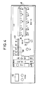
- La figure 4 représente la platine de contrôle du détecteur.
- La figure 5 est un schéma de la logique de commande.
- La figure 6 est un diagramme logique fonctionnel des différentes opérations.
- Figure 1 is a block diagram of the vacuum circuit of the leak detector according to the invention.
- Figures 2 and 3 schematically show in two views, the layout of the mechanical and electrical elements of the detector of the invention, in a suitcase.
- Figure 4 shows the detector's control board.
- Figure 5 is a diagram of the control logic.
- Figure 6 is a functional logic diagram of the various operations.
En se référant à la figure 1, on voit le schéma de vide du détecteur selon l'invention.Referring to Figure 1, we see the vacuum diagram of the detector according to the invention.
Il comprend une unique pompe 1 qui est une pompe secondaire turbomoléculaire et un analyseur de gaz 2 relié à l'entrée 3 de la pompe. La sortie 4 de la pompe est reliée à un orifice de raccordement formant bride 5 par l'intermédiaire d'une vanne d'entrée 6.It includes a
La vanne d'entrée 6 est une vanne électromagnétique commandée par l'intermédiaire d'une première jauge 7 de mesure de pression disposée entre la vanne d'entrée et la bride 5. Il s'agit par exemple d'une jauge thermique type Pirani.The
Le détecteur comporte encore une seconde jauge 8 de mesure de pression située au niveau de la pompe à vide 1 et du même type que la première jauge 7, et une troisième jauge 9, du type jauge triode, au niveau de l'analyseur de gaz 2.The detector also comprises a
Le détecteur est destiné à être relié à une enceinte à tester 10 qui est déjà sous vide ou bien qui peut être reliée à des moyens de pompages primaires 11. L'enceinte 10 possède une vanne de liaison 12. Le détecteur fonctionne selon le mode dit "à contre-courant".The detector is intended to be connected to an enclosure to be tested 10 which is already under vacuum or which can be connected to primary pumping means 11. The
L'ensemble des éléments du détecteur situé à l'intérieur du cadre A est logé dans une valise 13 représentée sur les figures 2 et 3 ; en revanche, les organes hors de ce cadre ne sont pas logés dans la valise : non seulement, bien entendu, l'enceinte à tester 10 mais aussi la vanne 12 et le groupe de pompage 11, sauf la canalisation de liaison amovible 14 qui peut trouver place dans la valise.All the elements of the detector located inside the frame A are housed in a
A l'intérieur de la valise sont en outre situés tous les accessoires nécessaires au fonctionnement du détecteur et notamment un transformateur d'alimentation 15, une carte de circuit imprimé 16 pour les circuits électroniques d'alimentation de la pompe 8, ainsi qu'une carte de circuit imprimé 17 pour les circuits électroniques de commande, d'automatisme et de signalisation et une platine 18 (figure 4) de contrôle comportant des cadrans d'affichage.Inside the case are also located all the accessories necessary for the operation of the detector and in particular a
L'ensemble est fixé sur un berceau 19 en aluminium qui comporte une platine supérieure 20 qui inclut la platine de contrôle 18.The assembly is fixed to an
La platine de contrôle 18 comporte, outre des éléments de contrôle et d'affichage, une manette de commande 21 de mise en marche du détecteur. Le transformateur 15 comporte un cordon d'alimentation, non représenté, pour sa liaison au secteur assurant la mise sous tension du détecteur.The control plate 18 comprises, in addition to control and display elements, a control lever 21 for switching on the detector. The
Les circuits électroniques de la carte de circuit imprimé 17 comportent entre autres un circuit logique de commande tel que celui représenté sur la figure 5.The electronic circuits of the printed circuit board 17 comprise inter alia a logic control circuit such as that shown in FIG. 5.
Ce circuit comprend une porte "OU" 22 dont la sortie commande le démarrage de la pompe 1 et qui comporte trois entrées 23, 24 et 25 provenant respectivement de la sortie de trois portes "ET" 26, 27 et 28.This circuit includes an "OR"
La porte "ET" 26 possède deux entrées 29 et 30. L'entrée 29 reçoit un signal, sur la ligne 31, lorsque la manette de commande 21 est actionnée et l'entrée 30 reçoit, par la ligne 40, un signal lorsque la pression, mesurée par la première jauge 7 est inférieure à une valeur déterminée, de 10 mbar dans le cas de l'exemple cité.The "AND"
La porte "ET" 27 possède également deux entrées 32 et 33. L'entrée 32 est reliée à la ligne 31 par un inverseur 34 et donc reçoit un signal lorsque la manette de commande 21 est en position de repos, non actionnée. L'entrée 33 est reliée à une ligne 35 qui reçoit un signal lorsque la pression indiquée par la seconde jauge 8 est inférieure à une valeur de consigne, de 5.10⁻² mbar dans le cas de l'exemple.The "AND"
Enfin, la porte "ET" 28 possède trois entrées 36, 37 et 38. L'entrée 36 est reliée à la ligne 35, l'entrée 37 à la ligne 31 et l'entrée 38 à la ligne 40 mais par l'intermédiaire d'un inverseur 39.Finally, the "AND"
Le circuit logique comprend en outre une porte "ET" 41 dont la sortie 42 commande, par l'intermédiaire d'une temporisation 43, l'ouverture de la vanne d'entrée 6. Cette porte "ET" 41 possède deux entrées 44 et 45 ; l'entrée 44 étant reliée à la ligne 40 et l'entrée 45 à la ligne 31.The logic circuit further comprises an "AND" gate 41 whose output 42 controls, by means of a
Ainsi, l'appareil étant mis sous tension, la pompe l démarre automatiquement et la vanne d'entrée 6 s'ouvre si la manette de commande 21 est actionnée et si la pression indiquée par la première jauge 7 descend au-dessous de la valeur déterminée de 10 mbar.Thus, with the apparatus energized, the pump l starts automatically and the
La mise en route de l'analyseur de gaz (le spectromètre de masse 2) est effectuée automatiquement dès que la pompe turbomoléculaire 1 atteint sa vitesse nominale, de 27000 tours/mn dans l'exemple, comme le figure la ligne 46 de la logique représentée figure 5.The gas analyzer (mass spectrometer 2) is started up automatically as soon as the
La temporisation 43 comporte une entrée d'inhibition 47 qui est reliée à la ligne 46.The
Comme on peut l'observer sur cette figure 5, le détecteur peut être conservé en état de marche, à condition qu'il soit toutefois sous tension, après avoir effectué un essai. En effet, si après un tel essai, on place en position de repos la manette de commande 21, la vanne d'entrée 6 se ferme puisque l'entrée 45 de la porte "ET" 41 n'est plus alimentée mais la pompe 1 est toujours alimentée car la porte "OU" 22 reste alors activée par son entrée 24 et en outre le spectromètre de masse 2 est toujours en état de marche car la pompe 1 fonctionne toujours à sa vitesse nominale.As can be seen in this figure 5, the detector can be kept in working order, provided that it is nevertheless powered, after having carried out a test. In fact, if after such a test, the control lever 21 is placed in the rest position, the
Si l'on veut effectuer un nouveau test sur la même enceinte, il suffit d'actionner de nouveau la manette de commande 21 et si la pression dans la canalisation 14 s'est maintenue inférieure à 10 mbar la vanne 6 s'ouvre si non, elle s'ouvrira dès que cette pression sera atteinte, grâce à la pompe 11.If a new test is to be carried out on the same enclosure, it is sufficient to actuate the control lever 21 again and if the pressure in the
Si l'on veut effectuer un test sur une autre enceinte, on relie la canalisation 14 à cette autre enceinte, on met en route le système de pompage de l'enceinte et on actionne la manette de commande 21. Dès que la pression dans cette canalisation descendra au-dessous de 10 mbar la vanne d'entrée 6 s'ouvre et le détecteur peut contrôler l'étanchéité de l'enceinte.If we want to perform a test on another enclosure, we connect the
La figure 6 donne un diagramme logique fonctionnel complet des différentes étapes de fonctionnement de l'appareil.FIG. 6 gives a complete functional logic diagram of the various stages of operation of the apparatus.
Sur la platine de contrôle de la figure 4, on voit le cadran d'affichage (en deux parties) 48 de la fuite mesurée, le cadran d'affichage 49 de la pression d'entrée, mesurée par la jauge 7, celui, 50, de la pression du spectromètre 2 ; en 51 un indicateur lumineux de l'état de la vanne d'entrée 6 ; en 52 un compteur horaire de fonctionnement et diverses autres indications ou touches de réglage qui ne sont pas essentielles à l'invention.On the control plate of FIG. 4, we see the display dial (in two parts) 48 of the measured leak, the
La valise 13 comporte un ventilateur 53 pour la ventilation des circuits électroniques et de l'électrovanne 6. En 54, on voit le préamplificateur du spectromètre de masse et en 55 l'aimant. La valise comporte une poignée 56 et une sangle de transport 57.The
Ainsi, le détecteur de l'invention inclus dans une valise présente de nombreux avantages : grâce à sa transportabilité, à son faible poids, de l'ordre de 18 kg, à sa robustesse, il accompagne le dépanneur dans ses déplacements quel que soit le mode de transport. Ceci est tout à fait nouveau : le dépanneur arrive sur le site avec son appareil.Thus, the detector of the invention included in a suitcase has many advantages: thanks to its transportability, its low weight, of the order of 18 kg, its robustness, it accompanies the convenience store in its movements whatever the mode of transport. This is completely new: the convenience store arrives on the site with its device.
En outre, aucun emballage n'est nécessaire, c'est la valise qui en tient lieu. Il n'y a plus d'attente en réception du détecteur chez le client, le dépanneur voyage et arrive sur le site avec son appareil.In addition, no packaging is necessary, the suitcase takes its place. There is no longer any waiting for reception of the detector at the customer, the convenience store travels and arrives on the site with his device.
Il n'y a aucune opérations préliminaires de mise en route : débridage de la pompe, vérification de niveau d'huile ; le détecteur peut être raccordé immédiatement sur l'enceinte à contrôler.There are no preliminary start-up operations: unlocking the pump, checking the oil level; the detector can be connected immediately to the enclosure to be tested.
Ainsi, grâce à ces avantages, ce détecteur peut remplir outre son rôle habituel de contrôle d'étanchéité, une fonction de dépannage d'urgence en cas de nécessité.Thus, thanks to these advantages, this detector can fulfill, in addition to its usual role of tightness control, an emergency repair function if necessary.
Claims (2)
Applications Claiming Priority (2)
| Application Number | Priority Date | Filing Date | Title |
|---|---|---|---|
| FR909001534A FR2658292B1 (en) | 1990-02-09 | 1990-02-09 | HELIUM LEAK DETECTOR OPERATING WITH A COUNTER-CURRENT, PORTABLE FOR TESTING AN ENCLOSURE HAVING ITS OWN PUMPING GROUP. |
| FR9001534 | 1990-02-09 |
Publications (3)
| Publication Number | Publication Date |
|---|---|
| EP0444434A2 true EP0444434A2 (en) | 1991-09-04 |
| EP0444434A3 EP0444434A3 (en) | 1991-09-18 |
| EP0444434B1 EP0444434B1 (en) | 1994-09-14 |
Family
ID=9393546
Family Applications (1)
| Application Number | Title | Priority Date | Filing Date |
|---|---|---|---|
| EP91101458A Expired - Lifetime EP0444434B1 (en) | 1990-02-09 | 1991-02-04 | Portable counter-flow helium leak detector for testing a vessel provided with its own pumping group |
Country Status (7)
| Country | Link |
|---|---|
| US (1) | US5134877A (en) |
| EP (1) | EP0444434B1 (en) |
| JP (1) | JP3091501B2 (en) |
| AT (1) | ATE111597T1 (en) |
| DE (1) | DE69103925T2 (en) |
| ES (1) | ES2060213T3 (en) |
| FR (1) | FR2658292B1 (en) |
Cited By (6)
| Publication number | Priority date | Publication date | Assignee | Title |
|---|---|---|---|---|
| WO1993012411A1 (en) * | 1991-12-07 | 1993-06-24 | Leybold Aktiengesellschaft | Leak indicator for vacuum systems and a method of searching for leaks in vacuum systems |
| EP0690980B1 (en) * | 1992-08-25 | 1998-03-04 | Balzers und Leybold Deutschland Holding Aktiengesellschaft | Vacuum leak detector for leak detection using light test gases |
| WO2000045144A1 (en) * | 1999-01-27 | 2000-08-03 | Inficon Gmbh | Test gas leakage detection apparatus |
| WO2002084246A3 (en) * | 2001-04-11 | 2003-04-24 | Inficon Gmbh | Leak indicator with test leak and test leak for integration into a leak indicator |
| CN106679895A (en) * | 2015-11-06 | 2017-05-17 | 北京卫星环境工程研究所 | Automatic leakage rate testing system applied to large space environment simulator |
| PL427779A1 (en) * | 2018-11-15 | 2019-04-08 | Instytut Techniki Budowlanej | Device for testing leak-tightness of installation products |
Families Citing this family (7)
| Publication number | Priority date | Publication date | Assignee | Title |
|---|---|---|---|---|
| IT1256824B (en) * | 1992-05-14 | 1995-12-21 | Varian Spa | PERFECTED HELIUM DETECTOR UNIT. |
| US5551285A (en) * | 1994-05-18 | 1996-09-03 | The United States Of America As Represented By The United States Department Of Energy | Leak checker data logging system |
| FR2784184B1 (en) | 1998-10-01 | 2000-12-15 | Cit Alcatel | COMPACT LEAK DETECTOR |
| DE10055057A1 (en) * | 2000-11-07 | 2002-05-08 | Pfeiffer Vacuum Gmbh | Leak detector pump has high vacuum pump, gas analyzer, test object connector, gas outlet opening, gas inlet opening, valve bodies and gas connections in or forming parts of housing |
| US6734422B2 (en) | 2001-03-21 | 2004-05-11 | Euv Llc | Portable outgas detection apparatus |
| CA2438448C (en) * | 2003-08-27 | 2008-11-18 | Quality Fabricating & Machining Ltd. | Leak detector |
| DE102006056215A1 (en) * | 2006-11-29 | 2008-06-05 | Inficon Gmbh | Sniffing leak detector |
Citations (6)
| Publication number | Priority date | Publication date | Assignee | Title |
|---|---|---|---|---|
| US4399690A (en) * | 1979-12-04 | 1983-08-23 | Varian Associates, Inc. | Vacuum leak detector having single valve assembly |
| DE3308555C1 (en) * | 1983-03-10 | 1984-07-19 | Cit-Alcatel GmbH, 6980 Wertheim | Apparatus for automatically measuring the leakage rate of a vessel |
| GB2133552A (en) * | 1982-12-24 | 1984-07-25 | Balzers Hochvakuum | Finding gas leaks in walls |
| GB2142150A (en) * | 1983-06-22 | 1985-01-09 | Varian Associates | Counterflow leak detector with cold trap |
| GB2190204A (en) * | 1986-05-09 | 1987-11-11 | Boc Group Plc | Search gas leak detector |
| EP0283543A1 (en) * | 1987-03-27 | 1988-09-28 | Leybold Aktiengesellschaft | Leak-detecting apparatus and its operating method |
Family Cites Families (3)
| Publication number | Priority date | Publication date | Assignee | Title |
|---|---|---|---|---|
| US3327521A (en) * | 1964-10-26 | 1967-06-27 | Nat Res Corp | Leak detector and vacuum pumping station |
| US4459844A (en) * | 1982-06-17 | 1984-07-17 | Smith & Denison | Gas separation chamber and portable leak detection system |
| US4583394A (en) * | 1984-08-07 | 1986-04-22 | Japan Atomic Energy Research Institute | Device and method for leak location |
-
1990
- 1990-02-09 FR FR909001534A patent/FR2658292B1/en not_active Expired - Fee Related
-
1991
- 1991-02-04 DE DE69103925T patent/DE69103925T2/en not_active Expired - Fee Related
- 1991-02-04 AT AT91101458T patent/ATE111597T1/en active
- 1991-02-04 ES ES91101458T patent/ES2060213T3/en not_active Expired - Lifetime
- 1991-02-04 EP EP91101458A patent/EP0444434B1/en not_active Expired - Lifetime
- 1991-02-07 JP JP03038013A patent/JP3091501B2/en not_active Expired - Fee Related
- 1991-02-08 US US07/652,738 patent/US5134877A/en not_active Expired - Lifetime
Patent Citations (6)
| Publication number | Priority date | Publication date | Assignee | Title |
|---|---|---|---|---|
| US4399690A (en) * | 1979-12-04 | 1983-08-23 | Varian Associates, Inc. | Vacuum leak detector having single valve assembly |
| GB2133552A (en) * | 1982-12-24 | 1984-07-25 | Balzers Hochvakuum | Finding gas leaks in walls |
| DE3308555C1 (en) * | 1983-03-10 | 1984-07-19 | Cit-Alcatel GmbH, 6980 Wertheim | Apparatus for automatically measuring the leakage rate of a vessel |
| GB2142150A (en) * | 1983-06-22 | 1985-01-09 | Varian Associates | Counterflow leak detector with cold trap |
| GB2190204A (en) * | 1986-05-09 | 1987-11-11 | Boc Group Plc | Search gas leak detector |
| EP0283543A1 (en) * | 1987-03-27 | 1988-09-28 | Leybold Aktiengesellschaft | Leak-detecting apparatus and its operating method |
Non-Patent Citations (2)
| Title |
|---|
| TECHNICA, septembre 1982, page 867, Z}rich, CH; "Tragbarer Massenspektrometer-Lecksucher" * |
| TECHNISCHES MESSEN, vol. 54, no. 3, 1987, pages 89-94, Munich, DE; C.J. K]NDIG: "Neue Wege beim Bau und der Anwendung von Helium-Lecksuchern" * |
Cited By (10)
| Publication number | Priority date | Publication date | Assignee | Title |
|---|---|---|---|---|
| WO1993012411A1 (en) * | 1991-12-07 | 1993-06-24 | Leybold Aktiengesellschaft | Leak indicator for vacuum systems and a method of searching for leaks in vacuum systems |
| US5537857A (en) * | 1991-12-07 | 1996-07-23 | Leybold Ag | Leak indicator for vacuum systems and a method of searching for leaks in vacuum systems |
| EP0690980B1 (en) * | 1992-08-25 | 1998-03-04 | Balzers und Leybold Deutschland Holding Aktiengesellschaft | Vacuum leak detector for leak detection using light test gases |
| WO2000045144A1 (en) * | 1999-01-27 | 2000-08-03 | Inficon Gmbh | Test gas leakage detection apparatus |
| US6550313B1 (en) | 1999-01-27 | 2003-04-22 | Inficon Gmbh | Test gas leakage detection apparatus |
| WO2002084246A3 (en) * | 2001-04-11 | 2003-04-24 | Inficon Gmbh | Leak indicator with test leak and test leak for integration into a leak indicator |
| US7107821B2 (en) | 2001-04-11 | 2006-09-19 | Inficon Gmbh | Leak indicator with test leak and test leak for integration into a leak indicator |
| US7444854B2 (en) | 2001-04-11 | 2008-11-04 | Inficon Gmbh | Leak indicator with test leak and test leak for integration into a leak detector |
| CN106679895A (en) * | 2015-11-06 | 2017-05-17 | 北京卫星环境工程研究所 | Automatic leakage rate testing system applied to large space environment simulator |
| PL427779A1 (en) * | 2018-11-15 | 2019-04-08 | Instytut Techniki Budowlanej | Device for testing leak-tightness of installation products |
Also Published As
| Publication number | Publication date |
|---|---|
| ATE111597T1 (en) | 1994-09-15 |
| JPH04213037A (en) | 1992-08-04 |
| FR2658292A1 (en) | 1991-08-16 |
| ES2060213T3 (en) | 1994-11-16 |
| EP0444434A3 (en) | 1991-09-18 |
| DE69103925T2 (en) | 1995-02-02 |
| US5134877A (en) | 1992-08-04 |
| FR2658292B1 (en) | 1994-09-16 |
| EP0444434B1 (en) | 1994-09-14 |
| DE69103925D1 (en) | 1994-10-20 |
| JP3091501B2 (en) | 2000-09-25 |
Similar Documents
| Publication | Publication Date | Title |
|---|---|---|
| EP0444434B1 (en) | Portable counter-flow helium leak detector for testing a vessel provided with its own pumping group | |
| EP0869344B1 (en) | Leak detector using a tracer gas | |
| FR2628835A1 (en) | ||
| FR2645362A1 (en) | ELECTRIC POWER CONTROL APPARATUS | |
| EP0033945B1 (en) | Helium-type leak detector | |
| FR2550641A1 (en) | APPARATUS FOR WARNING OF AN ABNORMAL CONDITION OF THE COOLING FLUID IN A COOLING CIRCUIT OF A SPACE | |
| EP0424830A1 (en) | Leak detecting system using tracer gas | |
| FR2602926A1 (en) | DEVICE FOR ADJUSTING AND DIALOGUE, IN PARTICULAR FOR A SPEED VARIATOR | |
| FR2667937A1 (en) | GAS LEAK DETECTOR. | |
| CH432861A (en) | Device for determining the position of a movable element in which a body coupled to the element is struck by a light beam | |
| FR2596900A1 (en) | Access control device | |
| FR2694631A1 (en) | Method and device for determining the phase of a compressed gas; method and device for transferring a compressed gas implementing them. | |
| EP0759008B1 (en) | Liquid dispenser | |
| FR2836206A1 (en) | Protection system for water distribution installation, comprises water flow meter of lower than billing accuracy, control unit which compares flow to reference value and closes valve if necessary | |
| JP3349569B2 (en) | Sampling fire detector | |
| EP0170754B1 (en) | Degasing, cleaning, blocking and recuperating combination with enhanced security for measuring apparatus | |
| FR2465280A1 (en) | FIRE ALARM INSTALLATION ESPECIALLY FOR A ROAD TUNNEL | |
| EP0008977A1 (en) | Apparatus for measuring a constituent of an atmosphere | |
| WO1998002857A1 (en) | Protection system against gas leakage | |
| JPS62293498A (en) | Gas accident prevention system | |
| FR3013071A1 (en) | DEVICE FOR DESENGINATING A LOCAL, DEVICE FOR SECURING A SITE AND METHOD FOR DEPLOYING A DEVICE FOR DISENGAGING A LOCAL | |
| EP0133297A2 (en) | Automatic arrangement for leak-testing a reservoir | |
| JPH085502A (en) | Gas leak detection device and gas meter with it | |
| FR2802633A1 (en) | Level detector for pressurized liquid gas in bottle and control system for gas bottle emptying, with swinging lever loss of load detector | |
| FR2514862A1 (en) | Automatic gas leakage detecting appts. - temporarily obstructs gas conduit while monitoring internal pressure and provides flow through auxiliary conduit in parallel |
Legal Events
| Date | Code | Title | Description |
|---|---|---|---|
| PUAI | Public reference made under article 153(3) epc to a published international application that has entered the european phase |
Free format text: ORIGINAL CODE: 0009012 |
|
| PUAL | Search report despatched |
Free format text: ORIGINAL CODE: 0009013 |
|
| AK | Designated contracting states |
Kind code of ref document: A2 Designated state(s): AT BE CH DE DK ES FR GB GR IT LI LU NL SE |
|
| AK | Designated contracting states |
Kind code of ref document: A3 Designated state(s): AT BE CH DE DK ES FR GB GR IT LI LU NL SE |
|
| 17P | Request for examination filed |
Effective date: 19920316 |
|
| 17Q | First examination report despatched |
Effective date: 19930825 |
|
| GRAA | (expected) grant |
Free format text: ORIGINAL CODE: 0009210 |
|
| AK | Designated contracting states |
Kind code of ref document: B1 Designated state(s): AT BE CH DE DK ES FR GB GR IT LI LU NL SE |
|
| PG25 | Lapsed in a contracting state [announced via postgrant information from national office to epo] |
Ref country code: GR Free format text: LAPSE BECAUSE OF FAILURE TO SUBMIT A TRANSLATION OF THE DESCRIPTION OR TO PAY THE FEE WITHIN THE PRESCRIBED TIME-LIMIT Effective date: 19940914 Ref country code: DK Effective date: 19940914 Ref country code: AT Effective date: 19940914 |
|
| REF | Corresponds to: |
Ref document number: 111597 Country of ref document: AT Date of ref document: 19940915 Kind code of ref document: T |
|
| REF | Corresponds to: |
Ref document number: 69103925 Country of ref document: DE Date of ref document: 19941020 |
|
| REG | Reference to a national code |
Ref country code: ES Ref legal event code: FG2A Ref document number: 2060213 Country of ref document: ES Kind code of ref document: T3 |
|
| ITF | It: translation for a ep patent filed |
Owner name: JACOBACCI CASETTA & PERANI S.P.A. |
|
| PG25 | Lapsed in a contracting state [announced via postgrant information from national office to epo] |
Ref country code: SE Effective date: 19941214 |
|
| GBT | Gb: translation of ep patent filed (gb section 77(6)(a)/1977) |
Effective date: 19941123 |
|
| PGFP | Annual fee paid to national office [announced via postgrant information from national office to epo] |
Ref country code: ES Payment date: 19950112 Year of fee payment: 5 |
|
| PG25 | Lapsed in a contracting state [announced via postgrant information from national office to epo] |
Ref country code: LU Free format text: LAPSE BECAUSE OF NON-PAYMENT OF DUE FEES Effective date: 19950228 Ref country code: BE Effective date: 19950228 |
|
| PGFP | Annual fee paid to national office [announced via postgrant information from national office to epo] |
Ref country code: NL Payment date: 19950228 Year of fee payment: 5 |
|
| PLBI | Opposition filed |
Free format text: ORIGINAL CODE: 0009260 |
|
| 26 | Opposition filed |
Opponent name: LEYBOLD AG Effective date: 19950613 |
|
| BERE | Be: lapsed |
Owner name: ALCATEL CIT Effective date: 19950228 |
|
| NLR1 | Nl: opposition has been filed with the epo |
Opponent name: LEYBOLD AG |
|
| PG25 | Lapsed in a contracting state [announced via postgrant information from national office to epo] |
Ref country code: ES Free format text: LAPSE BECAUSE OF THE APPLICANT RENOUNCES Effective date: 19960205 |
|
| PG25 | Lapsed in a contracting state [announced via postgrant information from national office to epo] |
Ref country code: NL Effective date: 19960901 |
|
| PLBO | Opposition rejected |
Free format text: ORIGINAL CODE: EPIDOS REJO |
|
| NLV4 | Nl: lapsed or anulled due to non-payment of the annual fee |
Effective date: 19960901 |
|
| APAC | Appeal dossier modified |
Free format text: ORIGINAL CODE: EPIDOS NOAPO |
|
| APAE | Appeal reference modified |
Free format text: ORIGINAL CODE: EPIDOS REFNO |
|
| APAC | Appeal dossier modified |
Free format text: ORIGINAL CODE: EPIDOS NOAPO |
|
| PLBN | Opposition rejected |
Free format text: ORIGINAL CODE: 0009273 |
|
| STAA | Information on the status of an ep patent application or granted ep patent |
Free format text: STATUS: OPPOSITION REJECTED |
|
| 27O | Opposition rejected |
Effective date: 19990430 |
|
| REG | Reference to a national code |
Ref country code: ES Ref legal event code: FD2A Effective date: 19991102 |
|
| REG | Reference to a national code |
Ref country code: GB Ref legal event code: IF02 |
|
| PGFP | Annual fee paid to national office [announced via postgrant information from national office to epo] |
Ref country code: GB Payment date: 20040204 Year of fee payment: 14 |
|
| PGFP | Annual fee paid to national office [announced via postgrant information from national office to epo] |
Ref country code: CH Payment date: 20040216 Year of fee payment: 14 |
|
| PGFP | Annual fee paid to national office [announced via postgrant information from national office to epo] |
Ref country code: DE Payment date: 20040217 Year of fee payment: 14 |
|
| PGFP | Annual fee paid to national office [announced via postgrant information from national office to epo] |
Ref country code: FR Payment date: 20040223 Year of fee payment: 14 |
|
| PG25 | Lapsed in a contracting state [announced via postgrant information from national office to epo] |
Ref country code: IT Free format text: LAPSE BECAUSE OF NON-PAYMENT OF DUE FEES;WARNING: LAPSES OF ITALIAN PATENTS WITH EFFECTIVE DATE BEFORE 2007 MAY HAVE OCCURRED AT ANY TIME BEFORE 2007. THE CORRECT EFFECTIVE DATE MAY BE DIFFERENT FROM THE ONE RECORDED. Effective date: 20050204 Ref country code: GB Free format text: LAPSE BECAUSE OF NON-PAYMENT OF DUE FEES Effective date: 20050204 |
|
| PG25 | Lapsed in a contracting state [announced via postgrant information from national office to epo] |
Ref country code: LI Free format text: LAPSE BECAUSE OF NON-PAYMENT OF DUE FEES Effective date: 20050228 Ref country code: CH Free format text: LAPSE BECAUSE OF NON-PAYMENT OF DUE FEES Effective date: 20050228 |
|
| PG25 | Lapsed in a contracting state [announced via postgrant information from national office to epo] |
Ref country code: DE Free format text: LAPSE BECAUSE OF NON-PAYMENT OF DUE FEES Effective date: 20050901 |
|
| GBPC | Gb: european patent ceased through non-payment of renewal fee |
Effective date: 20050204 |
|
| APAH | Appeal reference modified |
Free format text: ORIGINAL CODE: EPIDOSCREFNO |
|
| REG | Reference to a national code |
Ref country code: CH Ref legal event code: PL |
|
| PG25 | Lapsed in a contracting state [announced via postgrant information from national office to epo] |
Ref country code: FR Free format text: LAPSE BECAUSE OF NON-PAYMENT OF DUE FEES Effective date: 20051031 |
|
| REG | Reference to a national code |
Ref country code: FR Ref legal event code: ST Effective date: 20051031 |