EP0444425B1 - Drip irrigation lines - Google Patents
Drip irrigation lines Download PDFInfo
- Publication number
- EP0444425B1 EP0444425B1 EP91101190A EP91101190A EP0444425B1 EP 0444425 B1 EP0444425 B1 EP 0444425B1 EP 91101190 A EP91101190 A EP 91101190A EP 91101190 A EP91101190 A EP 91101190A EP 0444425 B1 EP0444425 B1 EP 0444425B1
- Authority
- EP
- European Patent Office
- Prior art keywords
- flow
- reducer
- drip irrigation
- tube
- strip
- Prior art date
- Legal status (The legal status is an assumption and is not a legal conclusion. Google has not performed a legal analysis and makes no representation as to the accuracy of the status listed.)
- Expired - Lifetime
Links
Images


Classifications
-
- A—HUMAN NECESSITIES
- A01—AGRICULTURE; FORESTRY; ANIMAL HUSBANDRY; HUNTING; TRAPPING; FISHING
- A01G—HORTICULTURE; CULTIVATION OF VEGETABLES, FLOWERS, RICE, FRUIT, VINES, HOPS OR SEAWEED; FORESTRY; WATERING
- A01G25/00—Watering gardens, fields, sports grounds or the like
- A01G25/02—Watering arrangements located above the soil which make use of perforated pipe-lines or pipe-lines with dispensing fittings, e.g. for drip irrigation
- A01G25/023—Dispensing fittings for drip irrigation, e.g. drippers
-
- Y—GENERAL TAGGING OF NEW TECHNOLOGICAL DEVELOPMENTS; GENERAL TAGGING OF CROSS-SECTIONAL TECHNOLOGIES SPANNING OVER SEVERAL SECTIONS OF THE IPC; TECHNICAL SUBJECTS COVERED BY FORMER USPC CROSS-REFERENCE ART COLLECTIONS [XRACs] AND DIGESTS
- Y02—TECHNOLOGIES OR APPLICATIONS FOR MITIGATION OR ADAPTATION AGAINST CLIMATE CHANGE
- Y02A—TECHNOLOGIES FOR ADAPTATION TO CLIMATE CHANGE
- Y02A40/00—Adaptation technologies in agriculture, forestry, livestock or agroalimentary production
- Y02A40/10—Adaptation technologies in agriculture, forestry, livestock or agroalimentary production in agriculture
- Y02A40/22—Improving land use; Improving water use or availability; Controlling erosion
Definitions
- the present invention relates to drip irrigation lines, and particularly to drip irrigation lines of the type including a continuous tube having a plurality of flow-reducer elements spaced longitudinally of the tube.
- Drip irrigation lines of the foregoing type are gaining widespread use because of their efficiency in the delivery of the irrigating water directly to the plant roots, and their substantial savings in the irrigation water required. Examples of drip irrigation lines that have been previously developed are described in US Patents 3,896,999, 4,307,841, 4,519,546, 4,687,143, 4,702,787 and 4,728,042.
- US Patent 4,728,042 describes a drip irrigation line, comprising a continuous tube having a plurality of flow-reducer elements spaced longitudinally of the tube, each of the flow-reducer elements comprising a strip formed with an inlet chamber at one end having an inlet opening, an outlet chamber at the opposite end having an outlet opening, and a flow-reducer path between the two chambers.
- a pressure responsive element in the form of a rubber member, is applied at the outlet chamber.
- EP-A-295 400 discloses a pressure compensating drip irrigation cylindrical one-piece emitter which is fixedly disposed within a tubular fluid carrying conduit line so as to define a flow path for fluid to escape from within the conduit line to the outside.
- the cylindrical emitter comprises inlet openings which provide communication from the inside of the conduit line to the flow path.
- the flow path comprises zig-zag deflection walls on the outer surface of the cylindrical emitter provided near the inlet openings, and a plurality of annular output regions (formed by a plurality of annular gapped support ribs provided on the outer surface of the cylindrical emitter) arranged between the zig-zag flow deflection path and a plurality of output orifices cut into the conduit line.
- a hollow deformable tubular member is provided which diametrically traverses the cylindrical emitter. Regulation is effected by deforming the tubular member in response to fluid pressure.
- a drip irrigation line comprising a continuous tube having a plurality of flow-reducer elements spaced longitudinally of the tube, each of the flow-reducer elements comprising a strip formed with an inlet chamber at one end having an inlet opening, an outlet chamber at the opposite end having an outlet opening, and a flow-reducer path between the two chambers; characterized in that said strip of each flow-reducer element is further formed with a connecting passageway between, and axially spaced from, the flow-reducer path and the outlet chambers, at least the portion of the strip forming the connecting passageway being of elastomeric material; said connecting passageway including a wide groove and a narrow groove extending through said wide groove and of a depth from the inner face of the tube greater than that of said wide groove.
- the differential pressure on the opposite faces of the elastomeric material imparts a flow-regulation characteristic to regulate the output flow under varying line pressures.
- relatively high line pressures tending to increase the flow output rate, increases the deformation of the elastomeric material at the connecting passageway which decreases the cross-sectional area of that passageway, thereby reducing the flow rate.
- relatively low line pressures tending to reduce the output flow rate, decreases the deformation of the elastomeric material at the connecting passageway, which increases the cross-sectional area of the passgeway, thereby increasing the flow rate. It has been found that effecting the regulation at the connecting passageway, and forming the connecting passageway with a wide groove and a narrow groove, enables better control of the regulation under varying line pressure conditions.
- each strip is of elastomeric material for the complete length of the flow-reducer path and of the connecting passageway, which thereby enables the flow-reducer elements to be produced by a one-shot moulding operation.
- each strip is of elastomeric material only for the length of the connecting passageway, which enables the flow-reducer elements to be produced in a two-shot moulding operation but using a single mould. In both cases, since only a single mould and a single moulding operation are required to produce the flow-reducer elements, the drip irrigation lines incorporating such elements may be produced in volume and at relatively low cost.
- the flow-reducer elements are separate discrete strips bonded at spaced intervals to a continuous, elongated, flexible element which is in turn bonded to one surface of the tube.
- the continuous, elongated, flexible element is of higher mechanical strength than that of the flow-reducer elements. This enhances the mechanical strength of the drip irrigation line, and thereby permits the tube to be made of thinner material, enabling a substantial saving in the cost of the line.
- the flow-reducer elements are supported by the continuous, elongated, flexible element, the flow-reducer elements need not have the rigidity that would otherwise be required when they are individually fed to the tube extruder, thereby enabling a savings in the costs of this material, and also decreasing the possibility of tearing or collapsing the extruded tube when rolled in the form of a reel.
- a plurality of the flow-reducer elements 11 are first injection moulded onto the continuous strip 12; and then tube 10 is extruded while concurrently feeding and bonding the continuous strip 12, and its flow-reducer elements 11, to the inner face of the extruded tube, the outlet openings being subsequently formed through the tube.
- the continuous strip 12 is preferably of plastic material having higher mechanical strength than the material of the flow-reducer elements 11, thereby enhancing the strength of the produced drip irrigation line while permitting both the tube 10 and the flow-reducer elements 11 to be made of thinner material. This method is also much more easily automated and requires simpler apparatus than the previously-used methods, such as described in the above-cited US Patent 4,728,042, wherein the dripper elements are individually fed to the extruder.
- Each of the flow-reducer elements 11 comprises a short strip which, when it and the continuous strip 12 are bonded to the inner face of tube 10, defines an inlet chamber 13 at one end and formed with two inlet openings 14 communicating with the interior of the tube 10; an outlet chamber 15 at the opposite end formed with an outlet opening 16 through the tube 10; a labyrinth 17 in the form of a zigzag passageway serving as a flow-reducer path for the water passing from the inlet chamber 13 to the outlet chamber 15; and a connecting portion 18 formed with a connecting passageway 19 between the labyrinth 17 and the outer chamber 15.
- Fig. 1 shows the elements in their non-operating conditions when no water pressure is applied. Under operating conditions, when the flow-reducer elements are subject to the line pressure, the depth of the connecting passageway 19 is even more reduced by the deformation of connecting portion 18, as will be described below.
- the connecting portion 18 is formed of three sections, namely: an end section 18a adjacent to the labyrinth 17 and increasing in depth towards the outlet chamber 15; an end section 18b adjacent to the outlet chamber 15 and decreasing in depth towards the outlet chamber; and an intermediate section 18c of substantially uniform depth, which depth is less than that of the labyrinth 17, the outlet chamber 15, and the inlet chamber 13, as described earlier.
- the connecting passageway 19 in connecting portion 18 includes a wide groove 19a, substantially of the same width as the width of the two chamber 13 and 15 and the labyrinth 17, and a narrow groove 19b extending centrally through the three sections 18a, 18b, 18c of connecting section 18 and of larger depth than the wide groove 19a, but still of smaller depth than that of the two chambers 13, 15 and labyrinth 17.
- the complete strip 11, including its labyrinth 17 and connecting portion 18, is made of an elastomeric material, such as natural or synthetic rubber, thermoplastic elastomers (TPE), polyurethane, etc.
- TPE thermoplastic elastomers
- the complete strip, particularly its connecting portion 18, is therefore deformable with pressure. Accordingly, when the water within the tube is under pressure, the connecting portion 18, is deflected towards the inner face of the tube, thereby closing the wide groove 19a. Accordingly, the narrow groove 19b will thereafter effect the regulation.
- the narrow groove 18b When the water pressure is unduly high, the narrow groove 18b will be reduced in cross-sectional area, thereby reducing the flow to the outlet chamber; whereas when the water pressure is relatively low, the narrow groove 18b will increase in cross-sectional area, thereby increasing the flow rate.
- each flow-reducer element 11 imparts a flow-regulation characteristic to the element, tending to maintain a relatively constant rate of flow to the outlet chamber 15 and outlet opening 16 under varying line pressure conditions.
- the drip irrigation line illustrated in Figs. 2, 2a and 2b is of similar construction as that illustrated in Figs. 1, 1a and 1b.
- the Fig. 2 construction also includes a tube 20 formed with a plurality of flow-reducer elements 21 spaced along its length bonded to a continuous, elongated strip 22, which latter strip is bonded to the inner face of the tube 20.
- This construction is also such that each flow-reducer element 21 defines an inlet chamber 23 formed with a pair of inlet openings 24; an outlet chamber 25 formed with an outlet opening 26; a labyrinth flow-reducer path 27; and a connecting portion 28 connecting the labyrinth to the outlet chamber.
- the connecting portion 28 in the construction illustrated in Figs. 2, 2a and 2b is also formed with the two end sections 28a, 28b, an intermediate section 28c, the wide groove 29a, and narrow central groove 29b, as described above with respect to Figs. 1, 1a and 1b.
- the narrow groove 29b is interrupted, and the interruption is bridged by a further groove 29c which is even narrower and shallower than the two opposite ends of the narrow groove 29b.
- Figs. 3, 3a and 3b illustrate a construction similar to that of Figs. 1, 1a and 1b, except that only the connecting portion 48 of each flow-reducer element 41 is made of elastomeric material, the remainder of the element being made of a non-elastomeric plastic material, such as polyethylene or polypropylene. Another difference is that each of the flow-reducer elements 41 is applied directly (e.g., by plastic welding) to the inner face of the tube 40, rather than being first applied to a continuous strip, such as strip 12 in Fig. 1. Each flow-reducer element 41 is otherwise of the same construction as element 11 in Fig.
- the flow-reducer element 11 illustrated in Fig. 1 can be produced by a single-shot injection moulding process since the complete element is made of the same plastic material, in the construction illustrated in Fig. 3, the flow-reducer element 41 is made by a two-shot injection moulding process, but still using the same mould, as illustrated in Figs. 4c and 4d.
- the first shot would be effected by injection moulding a non-elastomeric plastic material, such as polyethylene or polypropylene (Fig. 4c); and a few seconds thereafter, the elastomeric material defining the connecting portion 48 would be injected moulded, as shown in Fig. 4d, so as to be bonded to the non-elastomeric material.
- each of the flow-reducer elements 41 would be applied to the tube 40 at the time of extrusion if an extruded tube is produced, or to the face of the sheet used for making the tube if a seamed tube is produced.
- Figs. 4, 4a and 4b illustrate the construction of another flow-reducer element, therein designated 51, corresponding to the construction of Figs. 2, 2a, 2b, but using elastomeric material only for the connecting portion 58 formed with the connecting passageway 59 between the flow-reducer labyrinth 57 and outlet chamber 55.
- the remainder of the flow-reducer element 51 is of non-elastomeric material, such as polyethylene or polypropylene, produced as described above with respect to Fig. 4.
- the connecting portion 58 of the flow-reducer element 51 in Fig. 4 is constructed in the same manner as described above with respect to Fig. 2, including the three sections 58a, 58b and 58c, and the three types of grooves 59a, 59b and 59c constituting the connecting passageway between the labyrinth 57 and outlet chamber 55.
Description
- The present invention relates to drip irrigation lines, and particularly to drip irrigation lines of the type including a continuous tube having a plurality of flow-reducer elements spaced longitudinally of the tube.
- Drip irrigation lines of the foregoing type are gaining widespread use because of their efficiency in the delivery of the irrigating water directly to the plant roots, and their substantial savings in the irrigation water required. Examples of drip irrigation lines that have been previously developed are described in US Patents 3,896,999, 4,307,841, 4,519,546, 4,687,143, 4,702,787 and 4,728,042.
- US Patent 4,728,042, for example, describes a drip irrigation line, comprising a continuous tube having a plurality of flow-reducer elements spaced longitudinally of the tube, each of the flow-reducer elements comprising a strip formed with an inlet chamber at one end having an inlet opening, an outlet chamber at the opposite end having an outlet opening, and a flow-reducer path between the two chambers. In the described construction, a pressure responsive element, in the form of a rubber member, is applied at the outlet chamber.
- EP-A-295 400 discloses a pressure compensating drip irrigation cylindrical one-piece emitter which is fixedly disposed within a tubular fluid carrying conduit line so as to define a flow path for fluid to escape from within the conduit line to the outside. The cylindrical emitter comprises inlet openings which provide communication from the inside of the conduit line to the flow path. The flow path comprises zig-zag deflection walls on the outer surface of the cylindrical emitter provided near the inlet openings, and a plurality of annular output regions (formed by a plurality of annular gapped support ribs provided on the outer surface of the cylindrical emitter) arranged between the zig-zag flow deflection path and a plurality of output orifices cut into the conduit line. A hollow deformable tubular member is provided which diametrically traverses the cylindrical emitter. Regulation is effected by deforming the tubular member in response to fluid pressure.
- According to the present invention, there is provided a drip irrigation line comprising a continuous tube having a plurality of flow-reducer elements spaced longitudinally of the tube, each of the flow-reducer elements comprising a strip formed with an inlet chamber at one end having an inlet opening, an outlet chamber at the opposite end having an outlet opening, and a flow-reducer path between the two chambers; characterized in that said strip of each flow-reducer element is further formed with a connecting passageway between, and axially spaced from, the flow-reducer path and the outlet chambers, at least the portion of the strip forming the connecting passageway being of elastomeric material; said connecting passageway including a wide groove and a narrow groove extending through said wide groove and of a depth from the inner face of the tube greater than that of said wide groove.
- The differential pressure on the opposite faces of the elastomeric material imparts a flow-regulation characteristic to regulate the output flow under varying line pressures. Thus, relatively high line pressures tending to increase the flow output rate, increases the deformation of the elastomeric material at the connecting passageway which decreases the cross-sectional area of that passageway, thereby reducing the flow rate. On the other hand, relatively low line pressures, tending to reduce the output flow rate, decreases the deformation of the elastomeric material at the connecting passageway, which increases the cross-sectional area of the passgeway, thereby increasing the flow rate. It has been found that effecting the regulation at the connecting passageway, and forming the connecting passageway with a wide groove and a narrow groove, enables better control of the regulation under varying line pressure conditions.
- Several embodiments of the invention are described below for purposes of example. In some described embodiments, each strip is of elastomeric material for the complete length of the flow-reducer path and of the connecting passageway, which thereby enables the flow-reducer elements to be produced by a one-shot moulding operation. In other described embodiments, each strip is of elastomeric material only for the length of the connecting passageway, which enables the flow-reducer elements to be produced in a two-shot moulding operation but using a single mould. In both cases, since only a single mould and a single moulding operation are required to produce the flow-reducer elements, the drip irrigation lines incorporating such elements may be produced in volume and at relatively low cost.
- According to further features in some of the preferred embodiments of the invention described below, the flow-reducer elements are separate discrete strips bonded at spaced intervals to a continuous, elongated, flexible element which is in turn bonded to one surface of the tube. In such described embodiments, the continuous, elongated, flexible element is of higher mechanical strength than that of the flow-reducer elements. This enhances the mechanical strength of the drip irrigation line, and thereby permits the tube to be made of thinner material, enabling a substantial saving in the cost of the line. Also, since the flow-reducer elements are supported by the continuous, elongated, flexible element, the flow-reducer elements need not have the rigidity that would otherwise be required when they are individually fed to the tube extruder, thereby enabling a savings in the costs of this material, and also decreasing the possibility of tearing or collapsing the extruded tube when rolled in the form of a reel.
- Further features and advantages of the invention will be apparent from the description below.
- The invention is herein described, by way of example only, with reference to the accompanying drawings, wherein:
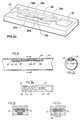
- Fig. 1 is a sectional view illustrating one form of drip irrigation line constructed in accordance with the invention, Fig. 1a being a sectional view along line a--a of Fig. 1, and Fig. 1b being a top view of the flow-reducer element;
- Figs. 2, 2a, 2b and 2c are corresponding views of another drip irrigation line constructed in accordance with the present invention;
- Figs. 3, 3a and 3b are views corresponding to Figs. 1, 1a and 1b of another drip irrigation line constructed in accordance with the present invention;
- Figs. 3c and 3d are enlarged fragmentary views illustrating the manner of producing each of the flow-reducer elements in the construction illustrated in Fig. 3 by a two-shot moulding method utilizing a single mould;
- Figs. 4, 4a and 4b are views corresponding to those of Figs. 1, 1a and 1b of another construction in accordance with the invention but showing only the flow-reducer element; and
- Figs. 1, 1a and 1b illustrate a drip irrigation line comprising a
continuous tube 10 having a plurality of flow-reducer elements, one being shown at 11, spaced longitudinally of the tube. The flow-reducer elements 11 are separate, discrete strips bonded at spaced intervals to a continuous, elongatedflexible strip 12.Strip 12 in turn is bonded to the inner face oftube 10. - Preferably, a plurality of the flow-
reducer elements 11 are first injection moulded onto thecontinuous strip 12; and thentube 10 is extruded while concurrently feeding and bonding thecontinuous strip 12, and its flow-reducer elements 11, to the inner face of the extruded tube, the outlet openings being subsequently formed through the tube. Thecontinuous strip 12 is preferably of plastic material having higher mechanical strength than the material of the flow-reducer elements 11, thereby enhancing the strength of the produced drip irrigation line while permitting both thetube 10 and the flow-reducer elements 11 to be made of thinner material. This method is also much more easily automated and requires simpler apparatus than the previously-used methods, such as described in the above-cited US Patent 4,728,042, wherein the dripper elements are individually fed to the extruder. - Each of the flow-
reducer elements 11 comprises a short strip which, when it and thecontinuous strip 12 are bonded to the inner face oftube 10, defines aninlet chamber 13 at one end and formed with twoinlet openings 14 communicating with the interior of thetube 10; anoutlet chamber 15 at the opposite end formed with an outlet opening 16 through thetube 10; alabyrinth 17 in the form of a zigzag passageway serving as a flow-reducer path for the water passing from theinlet chamber 13 to theoutlet chamber 15; and a connectingportion 18 formed with a connectingpassageway 19 between thelabyrinth 17 and theouter chamber 15. - As shown particularly in Fig. 1, the depth of the
inlet chamber 13,labyrinth 17, andoutlet chamber 15 are substantially the same, but the depth of theconnecting passageway 19 is somewhat shallower. It is to be understood that Fig. 1 (as well as the other figures illustrating other constructions as described below) shows the elements in their non-operating conditions when no water pressure is applied. Under operating conditions, when the flow-reducer elements are subject to the line pressure, the depth of the connectingpassageway 19 is even more reduced by the deformation of connectingportion 18, as will be described below. - As shown particularly in Fig. 1b, the connecting
portion 18 is formed of three sections, namely: anend section 18a adjacent to thelabyrinth 17 and increasing in depth towards theoutlet chamber 15; anend section 18b adjacent to theoutlet chamber 15 and decreasing in depth towards the outlet chamber; and anintermediate section 18c of substantially uniform depth, which depth is less than that of thelabyrinth 17, theoutlet chamber 15, and theinlet chamber 13, as described earlier. - As further seen in Fig. 1b, the
connecting passageway 19 in connectingportion 18 includes awide groove 19a, substantially of the same width as the width of the twochamber labyrinth 17, and anarrow groove 19b extending centrally through the threesections section 18 and of larger depth than thewide groove 19a, but still of smaller depth than that of the twochambers labyrinth 17. - In the embodiment illustrated in Figs. 1, 1a and 1b, the
complete strip 11, including itslabyrinth 17 and connectingportion 18, is made of an elastomeric material, such as natural or synthetic rubber, thermoplastic elastomers (TPE), polyurethane, etc. The complete strip, particularly its connectingportion 18, is therefore deformable with pressure. Accordingly, when the water within the tube is under pressure, the connectingportion 18, is deflected towards the inner face of the tube, thereby closing thewide groove 19a. Accordingly, thenarrow groove 19b will thereafter effect the regulation. When the water pressure is unduly high, thenarrow groove 18b will be reduced in cross-sectional area, thereby reducing the flow to the outlet chamber; whereas when the water pressure is relatively low, thenarrow groove 18b will increase in cross-sectional area, thereby increasing the flow rate. - In this manner, the connecting
portion 18 of each flow-reducer element 11 imparts a flow-regulation characteristic to the element, tending to maintain a relatively constant rate of flow to theoutlet chamber 15 and outlet opening 16 under varying line pressure conditions. - The drip irrigation line illustrated in Figs. 2, 2a and 2b is of similar construction as that illustrated in Figs. 1, 1a and 1b. Thus, the Fig. 2 construction also includes a
tube 20 formed with a plurality of flow-reducer elements 21 spaced along its length bonded to a continuous,elongated strip 22, which latter strip is bonded to the inner face of thetube 20. This construction is also such that each flow-reducer element 21 defines aninlet chamber 23 formed with a pair ofinlet openings 24; anoutlet chamber 25 formed with an outlet opening 26; a labyrinth flow-reducer path 27; and a connectingportion 28 connecting the labyrinth to the outlet chamber. - The connecting
portion 28 in the construction illustrated in Figs. 2, 2a and 2b is also formed with the twoend sections intermediate section 28c, thewide groove 29a, and narrowcentral groove 29b, as described above with respect to Figs. 1, 1a and 1b. In the construction of Figs. 2, 2a, 2b, however, thenarrow groove 29b is interrupted, and the interruption is bridged by afurther groove 29c which is even narrower and shallower than the two opposite ends of thenarrow groove 29b. This construction makes the connectingportion 28 of each flow-reducer element 21 more sensitive to pressure variations since the flow control is more greatly concentrated at thecenter section 29c of thenarrow groove 29b. - Figs. 3, 3a and 3b illustrate a construction similar to that of Figs. 1, 1a and 1b, except that only the connecting
portion 48 of each flow-reducer element 41 is made of elastomeric material, the remainder of the element being made of a non-elastomeric plastic material, such as polyethylene or polypropylene. Another difference is that each of the flow-reducer elements 41 is applied directly (e.g., by plastic welding) to the inner face of thetube 40, rather than being first applied to a continuous strip, such asstrip 12 in Fig. 1. Each flow-reducer element 41 is otherwise of the same construction aselement 11 in Fig. 1, including aninlet chamber 43 formed withinlet openings 44, anoutlet chamber 45 formed with anoutlet opening 46, a labyrinth flow-reducer path 47, and connectingportion 48 formed with aconnecting passageway 49 between the labyrinth and the outlet chamber. - Whereas the flow-
reducer element 11 illustrated in Fig. 1 can be produced by a single-shot injection moulding process since the complete element is made of the same plastic material, in the construction illustrated in Fig. 3, the flow-reducer element 41 is made by a two-shot injection moulding process, but still using the same mould, as illustrated in Figs. 4c and 4d. Thus, the first shot would be effected by injection moulding a non-elastomeric plastic material, such as polyethylene or polypropylene (Fig. 4c); and a few seconds thereafter, the elastomeric material defining the connectingportion 48 would be injected moulded, as shown in Fig. 4d, so as to be bonded to the non-elastomeric material. Since the construction illustrated in Fig. 3 does not utilize the continuous strip (12, Fig. 1), each of the flow-reducer elements 41 would be applied to thetube 40 at the time of extrusion if an extruded tube is produced, or to the face of the sheet used for making the tube if a seamed tube is produced. - Figs. 4, 4a and 4b illustrate the construction of another flow-reducer element, therein designated 51, corresponding to the construction of Figs. 2, 2a, 2b, but using elastomeric material only for the connecting
portion 58 formed with the connectingpassageway 59 between the flow-reducer labyrinth 57 andoutlet chamber 55. The remainder of the flow-reducer element 51 is of non-elastomeric material, such as polyethylene or polypropylene, produced as described above with respect to Fig. 4. The connectingportion 58 of the flow-reducer element 51 in Fig. 4 is constructed in the same manner as described above with respect to Fig. 2, including the threesections grooves labyrinth 57 andoutlet chamber 55.
Claims (7)
- A drip irrigation line, comprising a continuous tube (10; 20; 40) having a plurality of flow-reducer elements (11; 21; 41; 51) spaced longitudinally of the tube, each of said flow-reducer elements comprising a strip formed with an inlet chamber (13; 23; 43) at one end having an inlet opening (14; 24; 44), an outlet chamber (15; 25; 45; 55) at the opposite end having an outlet opening (16; 26; 46), and a flow-reducer path (17; 27; 47; 57) between said two chambers; characterized in that said strip of each flow-reducer element is further formed with a connecting passageway (19; 29; 49; 59) between, and axially spaced from, said flow-reducer path and said outlet chamber, at least the portion of the strip forming said connecting passageway being of elastomeric material; said connecting passageway including a wide groove (19a; 29a; 59a) and a narrow groove (19b; 29b; 59b) extending through said wide groove and of a depth from the inner face of the tube (10; 20; 40) greater than that of said wide groove.
- The drip irrigation line according to Claim 1, wherein the strip (12; 22) is of elastomeric material for the complete length of said flow-reducer path and of said connecting passageway.
- The drip irrigation line according to Claim 1, wherein the strip (48; 58) is of elastomeric material only for the length of said connecting passageway.
- The drip irrigation line according to Claim 1, wherein said narrow groove (29b) is formed with an interruption bridged by a further, narrower groove (29c).
- The drip irrigation line according to any one of Claims 1-4, wherein said flow-reducer elements (11; 21) are separate, discrete strips bonded at spaced intervals to a continuous, elongated, flexible element (12; 22) which is in turn bonded to one surface of said tube (10; 20).
- The drip irrigation line according to Claim 5, wherein said continuous, elongated, flexible element (12; 22) is of higher mechanical strength than the flow-reducer elements.
- The drip irrigation line according to any one of Claims 1-6, wherein said flow-reducer elements (42; 52) are separate, discrete strips bonded at spaced intervals to one face of said tube (40; 50).
Applications Claiming Priority (2)
| Application Number | Priority Date | Filing Date | Title |
|---|---|---|---|
| IL93255A IL93255A (en) | 1990-02-02 | 1990-02-02 | Drip irrigation lines |
| IL93255 | 1990-02-02 |
Publications (2)
| Publication Number | Publication Date |
|---|---|
| EP0444425A1 EP0444425A1 (en) | 1991-09-04 |
| EP0444425B1 true EP0444425B1 (en) | 1995-04-19 |
Family
ID=11060871
Family Applications (1)
| Application Number | Title | Priority Date | Filing Date |
|---|---|---|---|
| EP91101190A Expired - Lifetime EP0444425B1 (en) | 1990-02-02 | 1991-01-30 | Drip irrigation lines |
Country Status (6)
| Country | Link |
|---|---|
| US (1) | US5203503A (en) |
| EP (1) | EP0444425B1 (en) |
| AU (1) | AU644129B2 (en) |
| ES (1) | ES2071132T3 (en) |
| IL (1) | IL93255A (en) |
| ZA (1) | ZA91650B (en) |
Cited By (1)
| Publication number | Priority date | Publication date | Assignee | Title |
|---|---|---|---|---|
| US9485923B2 (en) | 2012-03-26 | 2016-11-08 | Rain Bird Corporation | Elastomeric emitter and methods relating to same |
Families Citing this family (56)
| Publication number | Priority date | Publication date | Assignee | Title |
|---|---|---|---|---|
| US5183208A (en) * | 1990-07-20 | 1993-02-02 | Agroteam Consultants Ltd. | Drip irrigation emitter |
| US5333793A (en) * | 1993-07-21 | 1994-08-02 | T-Systems International, Inc. | Drip irrigation hose with pressure compensation and method for its manufacture |
| FR2709400B1 (en) * | 1993-09-01 | 1995-12-15 | Pierre Jouglens | Drip device for crop irrigation system. |
| IL108171A (en) * | 1993-12-24 | 2000-01-31 | Hydromatic Ltd | Flow reducer devices and drip irrigation emitter including same |
| US5615838A (en) * | 1995-03-10 | 1997-04-01 | Drip Irrigation Systems, Ltd. | In-line retention drip emitter |
| US5688072A (en) * | 1995-12-14 | 1997-11-18 | Micro Irrigation Technologies, Inc. | Agricultural drip tape |
| US6120634A (en) * | 1997-02-26 | 2000-09-19 | Micro Irrigation Technologies, Inc. | Method and apparatus for forming agricultural drip tape |
| AU8297198A (en) * | 1997-07-09 | 1999-02-08 | T-Systems International, Inc. | Unibody pressure-compensating emitter |
| IL121967A (en) * | 1997-10-14 | 2001-06-14 | Hydro Plan Eng Ltd | Emitter unit |
| IL129817A (en) * | 1999-05-06 | 2002-12-01 | Plassim Tech Plastics Works | Method for producing an irrigation pipeline with inner emitters |
| US6620278B1 (en) | 2000-04-18 | 2003-09-16 | Nelson Irrigation Corporation | Drip tape manufacturing process |
| US6382530B1 (en) * | 2000-07-10 | 2002-05-07 | Nelson Irrigation Corporation | Pressure compensating drip tape |
| US6886761B2 (en) | 2000-08-21 | 2005-05-03 | Amir Cohen | Drip irrigation hose and method and apparatus for making same |
| US6736337B2 (en) | 2002-02-08 | 2004-05-18 | The Toro Company | Pressure compensating drip irrigation hose |
| US20030236489A1 (en) * | 2002-06-21 | 2003-12-25 | Baxter International, Inc. | Method and apparatus for closed-loop flow control system |
| US20050258279A1 (en) * | 2004-05-24 | 2005-11-24 | Nelson Irrigation Corporation | Pressure compensating drip tape and related method |
| WO2005115634A1 (en) | 2004-05-24 | 2005-12-08 | Amir Cohen | Drip irrigation hose and method for making same |
| US7270280B2 (en) * | 2004-06-21 | 2007-09-18 | Netafim Ltd. | Disc shape dripper |
| US8302887B2 (en) | 2005-03-31 | 2012-11-06 | Rain Bird Corporation | Drip emitter |
| US7648085B2 (en) | 2006-02-22 | 2010-01-19 | Rain Bird Corporation | Drip emitter |
| US7374109B2 (en) * | 2006-04-06 | 2008-05-20 | Crown Plastics Company | Rail cushion assembly |
| IL177552A (en) * | 2006-08-17 | 2014-08-31 | Ron Keren | Irrigation pipe |
| ES2328541B1 (en) * | 2006-11-08 | 2010-09-22 | Wind, S.L. | MANUFACTURING PROCESS OF AN ISSUER FOR DRIP IRRIGATION. |
| US8372326B2 (en) * | 2008-10-20 | 2013-02-12 | D.R.T.S. Enterprises Ltd. | Pressure compensated non-clogging drip emitter |
| US8663525B2 (en) | 2008-10-20 | 2014-03-04 | Shay Mamo | Internally pressure compensated non-clogging drip emitter |
| US7988076B2 (en) * | 2008-10-20 | 2011-08-02 | D.R.T.S. Enterprises Ltd. | Non-clogging non-pressure compensated drip emitter |
| US20100282873A1 (en) * | 2009-05-06 | 2010-11-11 | Mattlin Jeffrey L | Drip Emitter and Methods of Assembly and Mounting |
| US8317111B2 (en) | 2010-01-31 | 2012-11-27 | Amirim Products Development & Patents Ltd. | Bi-component drip emitter |
| US8511586B2 (en) | 2011-04-20 | 2013-08-20 | Deere & Company | Disc shaped regulated drip irrigation emitter |
| US10440903B2 (en) | 2012-03-26 | 2019-10-15 | Rain Bird Corporation | Drip line emitter and methods relating to same |
| US9877440B2 (en) | 2012-03-26 | 2018-01-30 | Rain Bird Corporation | Elastomeric emitter and methods relating to same |
| US20130248622A1 (en) | 2012-03-26 | 2013-09-26 | Jae Yung Kim | Drip line and emitter and methods relating to same |
| ES2672050T3 (en) * | 2012-05-24 | 2018-06-12 | Enplas Corporation | Drip irrigation emitter and drip irrigation device equipped with it |
| IL221089A (en) * | 2012-07-24 | 2016-05-31 | Einav Zvi | Integral drip irrigation emitter with an easy spreadable exit pool |
| US9345205B2 (en) | 2012-09-28 | 2016-05-24 | Enplas Corporation | Dripper for drip irrigation and drip irrigation device |
| US9439366B2 (en) * | 2012-12-17 | 2016-09-13 | Enplas Corporation | Dripper for drip irrigation, and drip-irrigation device provided with same |
| US9872444B2 (en) | 2013-03-15 | 2018-01-23 | Rain Bird Corporation | Drip emitter |
| US10285342B2 (en) | 2013-08-12 | 2019-05-14 | Rain Bird Corporation | Elastomeric emitter and methods relating to same |
| USD811179S1 (en) | 2013-08-12 | 2018-02-27 | Rain Bird Corporation | Emitter part |
| AU2014306803B2 (en) * | 2013-08-12 | 2018-02-22 | Rain Bird Corporation | Elastomeric emitter and methods relating to same |
| US10631473B2 (en) | 2013-08-12 | 2020-04-28 | Rain Bird Corporation | Elastomeric emitter and methods relating to same |
| US9883640B2 (en) | 2013-10-22 | 2018-02-06 | Rain Bird Corporation | Methods and apparatus for transporting elastomeric emitters and/or manufacturing drip lines |
| CN105792635A (en) * | 2013-11-27 | 2016-07-20 | 恩普乐股份有限公司 | Emitter and drip irrigation tube |
| ES2733624T3 (en) * | 2013-11-27 | 2019-12-02 | Enplas Corp | Emitter and drip irrigation tube |
| ES2734213T3 (en) * | 2013-11-27 | 2019-12-04 | Enplas Corp | Emitter and tube for drip irrigation |
| US9943045B2 (en) | 2013-11-27 | 2018-04-17 | Enplas Corporation | Emitter and drip irrigation tube |
| JP6417176B2 (en) * | 2014-10-07 | 2018-10-31 | 株式会社エンプラス | Emitter and drip irrigation tubes |
| ES2788630T3 (en) | 2013-12-16 | 2020-10-22 | Enplas Corp | Emitter and drip irrigation tube |
| US10383290B2 (en) * | 2014-01-10 | 2019-08-20 | Enplas Corporation | Emitter and drip irrigation tube |
| AU2015246007B2 (en) * | 2014-04-09 | 2018-08-02 | Roots Sustainable Agricultural Technologies Ltd. | Heat delivery system and method |
| US10330559B2 (en) | 2014-09-11 | 2019-06-25 | Rain Bird Corporation | Methods and apparatus for checking emitter bonds in an irrigation drip line |
| IL259460B (en) | 2015-12-03 | 2022-08-01 | Netafim Ltd | Drip emitter |
| US10375904B2 (en) | 2016-07-18 | 2019-08-13 | Rain Bird Corporation | Emitter locating system and related methods |
| US11051466B2 (en) | 2017-01-27 | 2021-07-06 | Rain Bird Corporation | Pressure compensation members, emitters, drip line and methods relating to same |
| US10626998B2 (en) | 2017-05-15 | 2020-04-21 | Rain Bird Corporation | Drip emitter with check valve |
| USD883048S1 (en) * | 2017-12-12 | 2020-05-05 | Rain Bird Corporation | Emitter part |
Family Cites Families (10)
| Publication number | Priority date | Publication date | Assignee | Title |
|---|---|---|---|---|
| US309162A (en) * | 1884-12-09 | Milk-can | ||
| US3870236A (en) * | 1973-03-14 | 1975-03-11 | Sahagun Barragan Jaime | Dripping irrigation tubing |
| US3896999A (en) * | 1973-09-28 | 1975-07-29 | Jaime Sahagun Barragan | Anti-clogging drip irrigation valve |
| US4023595A (en) * | 1974-07-30 | 1977-05-17 | Mifal Leyitzur Mamtirim Veavizarei Hashkaya Bekibbutz Dan | Flowrate control device |
| IL53463A (en) * | 1977-11-24 | 1982-11-30 | Hydro Plan Eng Ltd | Drip irrigation system |
| MX143576A (en) * | 1977-04-11 | 1981-06-03 | Jaime Sahagun Barragan | IMPROVEMENTS IN INTEGRAL DRIP IRRIGATION SYSTEM |
| IL63341A (en) * | 1981-07-15 | 1996-09-12 | Naan Mech Works | Drip irrigation apparatus |
| IT1196295B (en) * | 1984-10-15 | 1988-11-16 | Enichem Polimeri | DROP WING FOR LOCALIZED IRRIGATION |
| US4824025A (en) * | 1987-05-26 | 1989-04-25 | Miller David B | One-piece in-line pressure compensating drip irrigation emitter |
| US4817875A (en) * | 1987-09-21 | 1989-04-04 | David Karmeli | Flexible pipe for trickle irrigation |
-
1990
- 1990-02-02 IL IL93255A patent/IL93255A/en not_active IP Right Cessation
-
1991
- 1991-01-29 ZA ZA91650A patent/ZA91650B/en unknown
- 1991-01-29 US US07/647,099 patent/US5203503A/en not_active Expired - Lifetime
- 1991-01-30 ES ES91101190T patent/ES2071132T3/en not_active Expired - Lifetime
- 1991-01-30 EP EP91101190A patent/EP0444425B1/en not_active Expired - Lifetime
- 1991-02-01 AU AU70177/91A patent/AU644129B2/en not_active Ceased
Cited By (1)
| Publication number | Priority date | Publication date | Assignee | Title |
|---|---|---|---|---|
| US9485923B2 (en) | 2012-03-26 | 2016-11-08 | Rain Bird Corporation | Elastomeric emitter and methods relating to same |
Also Published As
| Publication number | Publication date |
|---|---|
| EP0444425A1 (en) | 1991-09-04 |
| IL93255A (en) | 1997-03-18 |
| ES2071132T3 (en) | 1995-06-16 |
| US5203503A (en) | 1993-04-20 |
| ZA91650B (en) | 1991-11-27 |
| AU644129B2 (en) | 1993-12-02 |
| AU7017791A (en) | 1991-08-08 |
| IL93255A0 (en) | 1990-11-29 |
Similar Documents
| Publication | Publication Date | Title |
|---|---|---|
| EP0444425B1 (en) | Drip irrigation lines | |
| EP0295400B1 (en) | One-piece in-line pressure compensating drip irrigation emitter | |
| US4210287A (en) | Drip irrigation system | |
| EP0467386B1 (en) | Drip irrigation emitters | |
| US4177946A (en) | Integral drip irrigation system | |
| AU635818B2 (en) | Pressure compensating drip irrigation system | |
| US9877441B2 (en) | Elastomeric emitter and methods relating to same | |
| US11185021B2 (en) | Elastomeric emitter and methods relating to same | |
| EP0636309B1 (en) | Regulated flow restrictor device particularly useful as a drip irrigation emitter | |
| US5246171A (en) | Drip irrigation tape including a series of alternately offset elongated chambers | |
| EP0709020B1 (en) | Constant-flow irrigation tape and method of making | |
| US6015102A (en) | External emitter for drip irrigation hose | |
| US6371390B1 (en) | Drip irrigation hose and method of making same | |
| US5236130A (en) | Drip irrigation apparatus | |
| US6403013B1 (en) | Method for producing a drip irrigation line | |
| AU2002311581A2 (en) | Irrigation apparatus having a lateral tube support | |
| AU2002311581A1 (en) | Irrigation apparatus having a lateral tube support | |
| EP0493299B1 (en) | Method of producing a drip irrigation pipe and a drip irrigation pipe | |
| KR100356723B1 (en) | Irrigation Hose | |
| EP0538242B1 (en) | Drip irrigation system employing adjacently arranged flow-restricting passages | |
| AU734482B2 (en) | External emitter for drip irrigation hose | |
| WO2021039831A1 (en) | Emitter and drip irrigation tube | |
| GB1596233A (en) | Integral drip irrigation system | |
| WO2005115634A1 (en) | Drip irrigation hose and method for making same | |
| MXPA00001729A (en) | External emitter for drip irrigation hose |
Legal Events
| Date | Code | Title | Description |
|---|---|---|---|
| PUAI | Public reference made under article 153(3) epc to a published international application that has entered the european phase |
Free format text: ORIGINAL CODE: 0009012 |
|
| AK | Designated contracting states |
Kind code of ref document: A1 Designated state(s): ES FR GR IT NL |
|
| 17P | Request for examination filed |
Effective date: 19920226 |
|
| 17Q | First examination report despatched |
Effective date: 19921208 |
|
| GRAA | (expected) grant |
Free format text: ORIGINAL CODE: 0009210 |
|
| AK | Designated contracting states |
Kind code of ref document: B1 Designated state(s): ES FR GR IT NL |
|
| ET | Fr: translation filed | ||
| ITF | It: translation for a ep patent filed |
Owner name: MODIANO & ASSOCIATI S.R.L. |
|
| REG | Reference to a national code |
Ref country code: GR Ref legal event code: FG4A Free format text: 3016686 |
|
| PLBE | No opposition filed within time limit |
Free format text: ORIGINAL CODE: 0009261 |
|
| STAA | Information on the status of an ep patent application or granted ep patent |
Free format text: STATUS: NO OPPOSITION FILED WITHIN TIME LIMIT |
|
| NLS | Nl: assignments of ep-patents |
Owner name: PLASTRO GVAT |
|
| REG | Reference to a national code |
Ref country code: FR Ref legal event code: TP |
|
| 26N | No opposition filed | ||
| REG | Reference to a national code |
Ref country code: ES Ref legal event code: PC2A Owner name: PLASTRO GVAT |
|
| PGFP | Annual fee paid to national office [announced via postgrant information from national office to epo] |
Ref country code: GR Payment date: 20011231 Year of fee payment: 12 |
|
| PGFP | Annual fee paid to national office [announced via postgrant information from national office to epo] |
Ref country code: NL Payment date: 20020116 Year of fee payment: 12 Ref country code: ES Payment date: 20020116 Year of fee payment: 12 |
|
| PGFP | Annual fee paid to national office [announced via postgrant information from national office to epo] |
Ref country code: FR Payment date: 20020130 Year of fee payment: 12 |
|
| PG25 | Lapsed in a contracting state [announced via postgrant information from national office to epo] |
Ref country code: ES Free format text: LAPSE BECAUSE OF NON-PAYMENT OF DUE FEES Effective date: 20030131 |
|
| PG25 | Lapsed in a contracting state [announced via postgrant information from national office to epo] |
Ref country code: NL Free format text: LAPSE BECAUSE OF NON-PAYMENT OF DUE FEES Effective date: 20030801 |
|
| PG25 | Lapsed in a contracting state [announced via postgrant information from national office to epo] |
Ref country code: GR Free format text: LAPSE BECAUSE OF NON-PAYMENT OF DUE FEES Effective date: 20030804 |
|
| PG25 | Lapsed in a contracting state [announced via postgrant information from national office to epo] |
Ref country code: FR Free format text: LAPSE BECAUSE OF NON-PAYMENT OF DUE FEES Effective date: 20030930 |
|
| NLV4 | Nl: lapsed or anulled due to non-payment of the annual fee |
Effective date: 20030801 |
|
| REG | Reference to a national code |
Ref country code: FR Ref legal event code: ST |
|
| REG | Reference to a national code |
Ref country code: ES Ref legal event code: FD2A Effective date: 20030131 |
|
| PG25 | Lapsed in a contracting state [announced via postgrant information from national office to epo] |
Ref country code: IT Free format text: LAPSE BECAUSE OF NON-PAYMENT OF DUE FEES;WARNING: LAPSES OF ITALIAN PATENTS WITH EFFECTIVE DATE BEFORE 2007 MAY HAVE OCCURRED AT ANY TIME BEFORE 2007. THE CORRECT EFFECTIVE DATE MAY BE DIFFERENT FROM THE ONE RECORDED. Effective date: 20050130 |