EP0444364B1 - Physical database design system - Google Patents
Physical database design system Download PDFInfo
- Publication number
- EP0444364B1 EP0444364B1 EP90314392A EP90314392A EP0444364B1 EP 0444364 B1 EP0444364 B1 EP 0444364B1 EP 90314392 A EP90314392 A EP 90314392A EP 90314392 A EP90314392 A EP 90314392A EP 0444364 B1 EP0444364 B1 EP 0444364B1
- Authority
- EP
- European Patent Office
- Prior art keywords
- database
- operations
- workload
- data
- physical
- Prior art date
- Legal status (The legal status is an assumption and is not a legal conclusion. Google has not performed a legal analysis and makes no representation as to the accuracy of the status listed.)
- Expired - Lifetime
Links
Images


Classifications
-
- G—PHYSICS
- G06—COMPUTING; CALCULATING OR COUNTING
- G06F—ELECTRIC DIGITAL DATA PROCESSING
- G06F16/00—Information retrieval; Database structures therefor; File system structures therefor
- G06F16/20—Information retrieval; Database structures therefor; File system structures therefor of structured data, e.g. relational data
- G06F16/22—Indexing; Data structures therefor; Storage structures
- G06F16/2228—Indexing structures
- G06F16/2272—Management thereof
-
- Y—GENERAL TAGGING OF NEW TECHNOLOGICAL DEVELOPMENTS; GENERAL TAGGING OF CROSS-SECTIONAL TECHNOLOGIES SPANNING OVER SEVERAL SECTIONS OF THE IPC; TECHNICAL SUBJECTS COVERED BY FORMER USPC CROSS-REFERENCE ART COLLECTIONS [XRACs] AND DIGESTS
- Y10—TECHNICAL SUBJECTS COVERED BY FORMER USPC
- Y10S—TECHNICAL SUBJECTS COVERED BY FORMER USPC CROSS-REFERENCE ART COLLECTIONS [XRACs] AND DIGESTS
- Y10S707/00—Data processing: database and file management or data structures
- Y10S707/99941—Database schema or data structure
- Y10S707/99943—Generating database or data structure, e.g. via user interface
Definitions
- the invention relates to the physical design of a database.
- Database systems are typically not self-optimizing in terms of their physical design. That is, they do not automatically alter the particular layout and storage characteristics of their data and operations. Most systems do include features that allow a user to specify certain settings, such as a choice of indexed or sequential keys for data records, the expected size of data files, or the storage locations of the data and program files. However, the appropriate settings of these and other features usually requires unique expertise that a general user does not possess.
- a human database expert therefore, is usually required to fine tune the physical design of a database in order to provide better runtime performance.
- the expert can make some improvements that yield a higher application throughput (i.e., a greater number of transactions processed) by reducing the number of necessary input/output operations (I/Os) and conducting more efficient buffering of data in memory.
- Other improvements include providing more efficient utilization of the central processing unit (CPU) and disk storage units by partitioning data across multiple disks, calculating optimal data density (i.e., providing large enough storage areas to contain each section of data), and calculating optimal placement of data within the data files.
- the physical structure of a database can be defined as the particular storage characteristics of a collection of interrelated data stored as one or more stored records.
- a stored record is the basic unit of storage which corresponds to one logical record and contains all pointers, record lengths, and other identifiers necessary to represent pieces of data.
- aspects of the physical structure of a database include, for example, the location and size of files, the access methods and keys to database records, and the placement of records within the database.
- the design of the physical structure has a significant impact on performance of the database as a whole. This impact, however, can differ from database to database (even among databases having the same physical structure).
- the physical structure's impact on performance can vary depending on the amount of data in the database (i.e., the "data volume”).
- the impact can also vary depending on the "physical constraints” of the system, e.g., the number of storage devices available, the amount of space available on the storage devices, the amount of I/O taking place, and the amount of random access memory (RAM) available.
- the impact can vary depending on the "workload” of the database, e.g., the type, frequency, priority, and sequence of database operations.
- the present invention provides a method for enabling a computer system to generate a physical database design, according to claim 1.
- the physical database design generated by the designer can be a relational database or a codasyl database.
- Another feature of the preferred embodiment provides that the designer compares the workload's different operations on the database by normalizing the hierarchical workload definition so that the operations are treated uniformly when creating the physical database design.
- the workload hierarchy includes at least three levels: programs, transactions within programs, and requests within transactions. A fourth level, applications, is possible as well and denotes groupings of related programs.
- the information contained in the workload definition includes the importance of operations at different levels of the hierarchy, the frequency of operations at different levels of the hierarchy, and the access mode and lock mode of transactions.
- one element of the improved physical database design generated by the designer is a definition of record placement, i.e., a particularly efficient storage layout for the data based on the workload and other inputs.
- the designer can use the following as inputs, (a) a volume definition for the database which includes information on the number of occurrences of the operation such as the volatility, the minimum and maximum number of occurrences; and (b) a physical constraints definition for the database which indicates the size of main memory available to the database, the size of disk memories on which records in the database are stored, and the maximum number of concurrent users of the database.
- the invention automates the design of the physical structure of a database and allows users to improve the performance of the database and any applications that rely on it.
- the system applies information regarding the data volume, physical constraints, and workload of the database to the design of the physical structure of the database.
- the information regarding the data volume and physical constraints can be generated by hand or input from various database dumps.
- the workload analysis can be generated by hand or by an application event-based data collector such as that described in a copending application by Philip K. Royal, entitled SYSTEM AND METHOD FOR APPLICATION EVENT COLLECTION, filed on even date with this application.
- the invention can be used to design databases that use storage space efficiently and that partition data across the available storage space to reduce the I/O overhead of database operations. For example, if the workload analysis indicates that operations on two particular objects (i.e., pieces of data) often occur in sequence, the invention recommends that objects be placed in proximity to one another on the storage device to minimize the number of I/O operations necessary to access the objects.
- the system can also size data according to the workload of the database and indicate how to arrange the data in "clusters" or groups within a database file. That is, the system stores related record types, e.g., all records processed by a particular database request or transaction, in the same area of the database. This technique helps to prevent excessive disk head movement that slows response time.
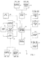
- Fig. 1 is a block diagram of the components of a physical database design system according to the present invention.
- Fig. 2 is a flow chart which illustrates the steps necessary to enter design inputs, i.e., logical schema, workload, volume, and constraints.
- Fig. 3 is a flow chart which illustrates the steps necessary to generate the physical structure.
- Fig. 4 is a flow chart which illustrates the steps necessary to output the creation parameters and runtime parameters to implement the physical structure.
- Table 1 is a sample logical database design (logical schema) used by the system.
- Table 2 is a sample workload definition used by the system.
- Table 3 is a sample data volume definition used by the system.
- Table 4 is a sample physical constraints definition used by the system.
- Table 5 (supplied in Appendix A) is a sample output of creation parameters and runtime parameters necessary to create the physical structure produced by the system.
- the present invention is a physical database design system 10 which assists a user in the fine tuning of a database by applying a set of rules to a logical database structure 14 (also referred to as a "logical schema").
- a logical database structure 14 also referred to as a "logical schema"
- the rule shown below determines whether a database table should be placed according to its type and index structure.
- Other example rules are supplied in Appendix A attached hereto.
- records of the same type and their associated index structure are stored on the same database page so that a retrieval of an index key at the particular page also retrieves the data associated with that key.
- the number of I/O operations caused by page retrievals is reduced and the performance of the database is improved.
- the logical schema 14 can be derived from several sources, including a database rootfile 16 or a database utility output 20.
- the database utility output is a language file, e.g., Data Definition Language (DDL), that is parsed via a YET Compiler Compiler (YACC) parser to create a generic internal representation, i.e., the logical schema 14.
- DDL Data Definition Language
- YACC YET Compiler Compiler
- the system 10 can accept and improve the design of any type of database, e.g., a CODASYL or a relational database.
- the system 10 relies upon the rules and also upon the following: a database workload definition 22, which can be generated by a human user 24 or derived from the output of an event performance collector 26; a data volume definition 28, which can be generated by the user or derived from a database rootfile 30 or database utility output such as the "database analyze output" 32 shown in Fig. 1; and a design constraints definition 34 which can be generated by the user.
- a database workload definition 22 which can be generated by a human user 24 or derived from the output of an event performance collector 26
- a data volume definition 28 which can be generated by the user or derived from a database rootfile 30 or database utility output such as the "database analyze output" 32 shown in Fig. 1
- a design constraints definition 34 which can be generated by the user.
- a physical database designer 36 also shown in Fig. 1 applies the information of the workload 22, the data volume 28, the design constraints 34, and the rules to the logical schema 14.
- the results of this application include a storage schema 38, i.e., a physical database structure which defines the on-disk structure of the logical schema 14. This physical structure is accompanied by a set of runtime parameters 42 and a set of creation parameters 44.
- the user can use the creation parameters 44 to implement the physical database structure 38, and use the runtime parameters 42 to unload data from an old database and reload it in the new database.
- the logical schema 14 of Fig. 1 can be thought of as defining record and field structures with which data entities are associated.
- An example of a logical schema 14 for a personnel database is shown below in Table 1.
- the schema includes a number of tables, i.e., COLLEGES, DEGREES, DEPARTMENTS, EMPLOYEES, JOBS, JOB_HISTORY, RESUMES, SALARY_HISTORY, and WORK_STATUS.
- Each table can be thought of as the definition of a record data structure.
- Each table also has a number of column elements which can be thought of as fields in the record.
- the COLLEGES table includes the column elements COLLEGE_CODE, COLLEGE_NAME, CITY, STATE, and POSTAL CODE.
- Each column element has associated with it a data type, e.g., character, integer, or date.
- the data entities which later fill the "rows" under the column elements can be related by their data type, but can also form relationships to one another by their appearance in multiple tables.
- the COLLEGE_CODE column element appears in the COLLEGES table and the DEGREES table.
- the database workload 22 defines database transactions performed on the data entities in the tables and column elements shown above and is described next in connection with an example workload for the personnel database.
- the database workload definition 22 describes the expected database operations on the data entities in the tables and column elements defined in the logical schema 14.
- the operations on the logical schema 14 i.e., applications, programs, transactions, and requests
- the workload 22 defines which tables of the logical schema 14 are accessed, how the tables are accessed (access mode, lock mode, and operation), how frequently they are accessed (frequency and cycle), and how important it is that a operation complete in the shortest time possible (importance).
- Access to data entities in a table is defined by several conditions.
- an access mode statement defines the type of operation that a particular column element is the object of, e.g., a READ, WRITE, or UPDATE operation.
- a lock mode statement defines whether the data entity can be accessed simultaneously by more than one operation, e.g., whether the column element allows SHARED, EXCLUSIVE, or PROTECTED access.
- data entities in the EMPLOYEES table shown above are accessed by a CHECK_DEPT_INFO transaction which defines all requests for operations on the table as READ ONLY and SHARED.
- the column elements by which data entities in a table are usually accessed are specified in requests. For example, in the request DEPTCODE_1 shown in Table 2 the data entities in the table DEPARTMENTS are accessed by the DEPARTMENT_CODE column element.
- the frequency of access to a table is defined by the number of times the data entities in a table are accessed in a particular cycle of time, i.e., the number of times per hour, day, week, month, quarter, or year. If a table is usually accessed by a particular column element, the frequency of access via that element can be very high in a single cycle. For example, the EMPLOYEES table might be accessed by the EMPLOYEE_ID column element 50 or 100 times a day. On the other hand, if an table is seldom accessed by the contents of a different column element, the frequency of access can be very low in a single cycle. For example, the EMPLOYEE table might be accessed by the ADDRESS_DATA_1 column element only once a week.
- the importance of an application, program, or transaction is a ranking on a scale of one to ten which corresponds to how important it is that the operation complete in the shortest time possible. For example, an application might be considered fairly important and rank a score of 8, while a program within the application might be very important and rank a score of 10. In some specific cases, rankings may seem to conflict with one another. For example, a transaction that looks up an employee's phone number and is performed many times a day, may seem at first to outrank a transaction which looks up an employee's address for payroll processing once a week. However, the payroll processing is likely considered a transaction which outranks other transactions and so requires a higher rating.
- the importance ratings determine several details of the final storage schema 38, e.g., the critical access paths in the schema.
- a user can create a workload definition 22 that identifies which aspects of the database design to optimize.
- An application is a collection of programs that perform a distinct business function.
- the "EMPLOYEES" application shown in Table 2 above retrieves and updates information about a company's employees, via individual programs such as "JOBINFO.”
- applications are typically not defined by an access mode, lock mode, frequency, or cycle since they are merely a means for grouping related programs.
- the importance of the application is defined, specifically, as a function of the importance of the programs within the application.
- the EMPLOYEES application is rated at 8.
- a program e.g., JOBINFO
- JOBINFO is a collection of transactions which performs a specific function or task.
- the workload 22 defines s separate program for each executable image or command procedure that accesses the database, e.g., application programs, or VAX Datatrieve, SQL, or DBQ procedures.
- the frequency, cycle, and importance for each program is defined.
- the cycle of the JOBINFO program is defined as DAILY, its frequency is 80.00, and its importance is 10.
- JOBINFO includes the transactions CHECK_DEPT_INFO, CHECK_EMPLOYEE_EXISTENCE, and CHECK_JOB_INFO.
- the access mode for the CHECK_DEPT_INFO transaction is defined as READ ONLY, the lock mode is SHARED, the frequency is 1.00, and the importance is 10. Note that all transactions have the same cycle, i.e., one execution of the program.
- each transaction is a collection of requests, i.e., single database accesses.
- Each access is written in a database language such as SQL or DML.
- the workload definition 22 as defined above is input to the physical database designer 36 and analyzed by an expert system to create an optimal physical design. A description of the analysis done by the expert system on the workload 22 is presented below.
- the analysis and characterization of the workload 22 is the first step in the design process once all of the design inputs have been obtained.
- the analysis includes the steps of annualizing the frequencies based on processing cycle, normalizing the frequencies for the transactions and requests, and creating an absolute importance for each request.
- the expert system within the physical database designer 36 contains a module KB_ANALYSIS which performs several operations on the workload data in order to determine certain details of the improved database design, i.e., the final storage structure 38.
- KB_ANALYSIS "annualizes" the occurrences of each request in the workload definition 22. That is, it converts the number of occurrences from the number of occurrences per cycle to the number of occurrences per year. For example, if the cycle is hourly, KB_ANALYSIS annualizes the number of occurrences by multiplying hours per day * days per week * weeks per month * months per quarter * quarters per year.
- KB_ANALYSIS "normalizes" the occurrences of transactions and requests so that the execution counts can be accurately compared. To do this, KB_ANALYSIS first updates the absolute count of transactions by multiplying the execution count of transactions by the execution count of programs and assigning the result to the absolute count of transactions. Then, KB_ANALYSIS updates the absolute number of requests by multiplying the absolute count of transactions by the execution count of requests and assigning the result to the absolute number of requests.
- KB_ANALYSIS combines the requests of all transactions in the workload definition 22 into one access path to each data entity for every type of access defined in the workload. To do this, KB_ANALYSIS sorts all requests in a particular order, e.g., by each "break" in the sort order, i.e., by design, retrieval_mode, verb, adverb, object, select_type, or select_object. KB_ANALYSIS also sums the importance at each break in the sort order.
- the data volume definition 28 of Fig. 1 describes the amount of data in the database.
- the system 10 uses this information in several ways, e.g., to optimize the size and number of database files, areas within the files.
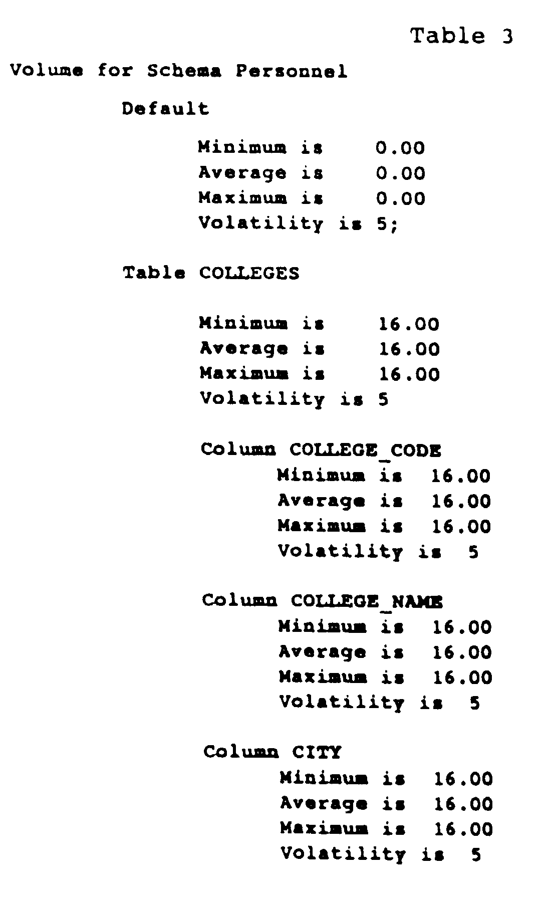
- the data volume is defined as the minimum, average, and maximum number of occurrences of each table and column element, as well as the volatility of the tables and elements.
- an employee database might contain one EMPLOYEES table for all employees in a company. Therefore, the minimum number of occurrences of data entities in the EMPLOYEES table is equal to the number of employees. Over time, however, the number of employees can vary. This variance is accounted for in the average and maximum number of occurrences of data entities in the EMPLOYEES table. For example, if the company expects to double its number of employees, the average and maximum numbers of entities in the EMPLOYEES table is increased in the data volume definition.
- the system allows users to rate the volatility of each table and column element on a scale of one to ten (one for very stable and ten for very volatile).
- the number of entities in the EMPLOYEES table can be somewhat volatile, e.g., subject to many additions and deletions, and receive a rating of 8.
- the number of entities in the COLLEGES table may be quite stable and receive a rating of 2. If the number of entities in a table is likely to change no more or no less than the number of other entities in the database, the table is or column element is typically assigned a volatility rating of 5.
- Table 3 shows an example volume definition for the personnel database.
- the overall definition is assigned default values of zero occurrences and a middle range volatility rating of 5.
- each table and column entry is assigned values to indicate the number of occurrences of entities in the table or column and its volatility.
- the number of occurrences of data entities in the COLLEGES table has a minimum, average, and maximum value of 16, and a volatility of 5.
- the final input to the physical database designer 36 i.e., the design constraints definition 34 is described below.
- the design constraints definition 34 of Fig. 1 describes the constraints on the physical resources used by the database, and is used to help create the storage schema 38.
- the constraints include the maximum number of users permitted to access the database at one time, the number of storage devices available to store files associated with the database, the maximum amount of space available on any one of the devices, the maximum amount of memory available to applications using the database (roughly half the amount of free memory), and the percentage of available memory to be used by applications. For example, if two thirds of the available system memory is to be used by the database applications, the available memory is 67%.
- Table 4 shows design constraint definition for the personnel database.
- the number of storage devices, i.e., disks, is 10 and provides 100,000 blocks of disk storage for 50 users.
- the maximum amount of memory available to applications is 64 megabytes, and the applications actually use 96% of the available memory.
- Fig. 2 is a flow chart which illustrates the steps of entering the design inputs, i.e., the logical schema 14, the workload 22, the constraints, 34, and the data volume 28.
- the physical database designer 36 creates a physical design into which it will store the results of its work. To initiate this process, the designer 36 prompts the user for the file name of a logical schema 14 and workload 22 to use as inputs to the design process (step 100).
- the designer 36 creates an instance of the logical schema 14 (step 102) and checks to see that the schema is unique (step 104), i.e., that there are no other instances of the same logical schema and only one logical schema for the physical design. If the schema 14 is not unique, the designer 36 returns an error (step 106). Otherwise, i.e., if the schema 14 is unique, the designer 36 creates instances for each table and column element in the schema (step 108).
- the designer 36 creates volume instances for each table and column element in the logical schema (step 112).
- the designer 36 next creates a instance of the workload 22 (step 114) and checks to see that the workload is unique (step 116), i.e., that there is one workload only for the physical design. If the workload 22 is not unique, the designer 36 returns an error (step 118). Otherwise, i.e., if the workload 22 is unique, the designer 36 creates an instance for each request, transaction, program, and application in the workload 22 (step 120). Finally, the designer 36 validates each request instance against the table and column element instances for the logical schema and prompts the user to resolve any inconsistencies (step 122).
- the runtime parameters 42 and creation parameters 44 of Fig. 1 are contained in a command procedure, e.g., a series of Digital Command Language (DCL) commands, which the user can use to implement the improved database. That is, when the command procedure is run, it unloads the data entities from an existing database, optimizes the physical design of the database, and reloads the data entities into a new database built upon the optimized design.
- DCL Digital Command Language
- the command procedure shown in Table 5 provides the user with information regarding the optimization process it is undertaking and allows the user an opportunity to change the input to various steps in the process. For example, if the database has tables of data entities which depend upon one another, i.e., have matching records in them, then the procedure prompts the user to edit a load sequence so that the tables are loaded in the proper order. Next, the procedure instructs the user as to what is necessary to implement the new database, e.g., a logical schema and enough space to temporarily store the data found in the tables of the existing database. And finally, the procedure informs the user as to how the storage of the data entities has been optimized and offers the user an opportunity to change the optimization.
- the procedure informs the user as to how the storage of the data entities has been optimized and offers the user an opportunity to change the optimization.
- the procedure proceeds to unload the data entities from the existing database.
- the procedure defines the new database, creates storage areas according to the storage schema 38, and creates storage maps for tables, i.e., mapping of the tables to areas of the database.
- the procedure sorts the unloaded data entities from the old database, and loads the sorted data entities into the new database.
- the process followed by the command procedure in the runtime parameters 42 and the creation parameters 44 can be further documented in various textual reports.
- Fig. 3 is a flow chart illustrating steps which an expert system in concert with the designer 36 takes in order to generate an optimal physical design.
- the designer 36 analyzes the applications, programs, transactions and requests to determine the access entries to each data entity (step 302). Having analyzed the necessary aspects of each data entity, the designer 36 next retrieves the importance for each request in the transaction and program (step 304) and determines the critical access to each data entity (step 306).
- the designer 36 analyzes the critical access methods entries to determine the desired access mode and access field for each data entity (step 308). Having completed its analysis, the designer 36, then creates access method instances for each unique critical access and data entity combination (step 310). Following step 310, the designer 36 analyzes the critical access entries to determine placement instance for each data entity (step 312). The designer also analyzes transaction instances (for relational databases) or relationship instances (for CODASYL databases) and request instances to determine the interrelationships between data entities (step 314). Once the analysis is complete, the designer 36, generates clusters for interrelated data entities (step 316).
- the designer 36 analyzes clusters to determine the mapping of entities to storage areas and storage maps (step 318) and creates instances of storage areas, storage maps, storage partitions, and storage indices (step 320). Once the instances are created, the designer 36 uses the access methods to determine storage index (step 322) and also uses the clusters and placements to determine storage area and storage map (step 324). Finally, the designer 36 prompts the user to determine the storage partitions (step 326) and creates load sequence instances using the volume, request, cluster, and storage map instances (step 328).
- Fig. 4 is a flow chart illustrating the steps of producing the logical schema 40, the storage schema 38, and the creation parameters 44 and runtime parameters 42.
- the designer 36 creates the new logical schema 40. To do this, the designer accesses instances of the logical schema, data entities, attributes, and relationships to create model specific Data Definition Language (DDL) file (step 400).
- the designer 36 creates the storage schema 38. To do this, the designer 36 accesses instances of the record format, storage schema, storage area, storage map, storage index, and storage partition to create model specific DDL file (step 402).
- the designer 36 creates the creation parameters 44. To do this, the designer 36 accesses instances of the storage area, implementation product, and design constraints to create model specific creation commands (step 404).
- the designer creates the runtime parameters 42. To do this, the designer 36 accesses instances of the implementation product, design constraints, storage area, and storage map to create model specific runtime commands (step 406).
- DDL Data Definition Language
- the designer 36 creates various textual reports such as a design report.
- the designer 36 accesses instances of logical schema, access method, placement, cluster, storage schema, storage area, storage map, and load sequence and writes descriptions of each to the report (step 410).
- the design report 48 is useful, for example, in explaining to a user why the system 10 chose the parameters and schema characteristics it did.
- the report is also useful in determining if the system used the appropriate inputs to generate the storage schema 38.
- the source code for the physical database designer (supplied in Appendix C and incorporated herein by reference) embodies the software modules described above.
- the programming languages used are VAX C version 3.0-031.
- the computer used is a VAX 8820 and the operating system used is VAX/VMS version 5.2.
- the modules are intended to run under DECwindows, but can also run under a DCL command line interface. Also a list of database design rules and heuristics coded in the relational data manipulation language, e.g., VAX SQL, is included in Appendix A.
Landscapes
- Engineering & Computer Science (AREA)
- Theoretical Computer Science (AREA)
- Software Systems (AREA)
- Data Mining & Analysis (AREA)
- Databases & Information Systems (AREA)
- Physics & Mathematics (AREA)
- General Engineering & Computer Science (AREA)
- General Physics & Mathematics (AREA)
- Information Retrieval, Db Structures And Fs Structures Therefor (AREA)
- Devices For Executing Special Programs (AREA)
- Stored Programmes (AREA)
Description
- The invention relates to the physical design of a database.
- Database systems are typically not self-optimizing in terms of their physical design. That is, they do not automatically alter the particular layout and storage characteristics of their data and operations. Most systems do include features that allow a user to specify certain settings, such as a choice of indexed or sequential keys for data records, the expected size of data files, or the storage locations of the data and program files. However, the appropriate settings of these and other features usually requires unique expertise that a general user does not possess.
- A human database expert, therefore, is usually required to fine tune the physical design of a database in order to provide better runtime performance. For example, the expert can make some improvements that yield a higher application throughput (i.e., a greater number of transactions processed) by reducing the number of necessary input/output operations (I/Os) and conducting more efficient buffering of data in memory. Other improvements include providing more efficient utilization of the central processing unit (CPU) and disk storage units by partitioning data across multiple disks, calculating optimal data density (i.e., providing large enough storage areas to contain each section of data), and calculating optimal placement of data within the data files.
- As noted, the physical structure of a database can be defined as the particular storage characteristics of a collection of interrelated data stored as one or more stored records. A stored record is the basic unit of storage which corresponds to one logical record and contains all pointers, record lengths, and other identifiers necessary to represent pieces of data. Aspects of the physical structure of a database include, for example, the location and size of files, the access methods and keys to database records, and the placement of records within the database. Not surprisingly, the design of the physical structure has a significant impact on performance of the database as a whole. This impact, however, can differ from database to database (even among databases having the same physical structure). For example, the physical structure's impact on performance can vary depending on the amount of data in the database (i.e., the "data volume"). The impact can also vary depending on the "physical constraints" of the system, e.g., the number of storage devices available, the amount of space available on the storage devices, the amount of I/O taking place, and the amount of random access memory (RAM) available. And finally, the impact can vary depending on the "workload" of the database, e.g., the type, frequency, priority, and sequence of database operations.
- IEEE Transactions on Software Engineering Vol. 14, No. 9; P. Rullo & D. Sacca: "An Automatic Physical Designer for Network Model Databases" describes an automated system which provides optimization algorithms for selecting an access path configuration (ie. a primary index and set of secondary indexes) which attempt to minimize the cost of all operations on the database.
- The present invention provides a method for enabling a computer system to generate a physical database design, according to claim 1. In preferred embodiments, the physical database design generated by the designer can be a relational database or a codasyl database. Another feature of the preferred embodiment provides that the designer compares the workload's different operations on the database by normalizing the hierarchical workload definition so that the operations are treated uniformly when creating the physical database design. Also, the workload hierarchy includes at least three levels: programs, transactions within programs, and requests within transactions. A fourth level, applications, is possible as well and denotes groupings of related programs. In the embodiment discussed below, the information contained in the workload definition includes the importance of operations at different levels of the hierarchy, the frequency of operations at different levels of the hierarchy, and the access mode and lock mode of transactions. Other types of information might likewise be stored. Finally, one element of the improved physical database design generated by the designer is a definition of record placement, i.e., a particularly efficient storage layout for the data based on the workload and other inputs. For example, the designer can use the following as inputs, (a) a volume definition for the database which includes information on the number of occurrences of the operation such as the volatility, the minimum and maximum number of occurrences; and (b) a physical constraints definition for the database which indicates the size of main memory available to the database, the size of disk memories on which records in the database are stored, and the maximum number of concurrent users of the database.
- The invention automates the design of the physical structure of a database and allows users to improve the performance of the database and any applications that rely on it. To do this, the system applies information regarding the data volume, physical constraints, and workload of the database to the design of the physical structure of the database. The information regarding the data volume and physical constraints can be generated by hand or input from various database dumps. Likewise, the workload analysis can be generated by hand or by an application event-based data collector such as that described in a copending application by Philip K. Royal, entitled SYSTEM AND METHOD FOR APPLICATION EVENT COLLECTION, filed on even date with this application.
- The invention can be used to design databases that use storage space efficiently and that partition data across the available storage space to reduce the I/O overhead of database operations. For example, if the workload analysis indicates that operations on two particular objects (i.e., pieces of data) often occur in sequence, the invention recommends that objects be placed in proximity to one another on the storage device to minimize the number of I/O operations necessary to access the objects. In addition, the system can also size data according to the workload of the database and indicate how to arrange the data in "clusters" or groups within a database file. That is, the system stores related record types, e.g., all records processed by a particular database request or transaction, in the same area of the database. This technique helps to prevent excessive disk head movement that slows response time.
- Other advantages and features will become apparent from the following description, and from the claims.
- Fig. 1 is a block diagram of the components of a physical database design system according to the present invention.
- Fig. 2 is a flow chart which illustrates the steps necessary to enter design inputs, i.e., logical schema, workload, volume, and constraints.
- Fig. 3 is a flow chart which illustrates the steps necessary to generate the physical structure.
- Fig. 4 is a flow chart which illustrates the steps necessary to output the creation parameters and runtime parameters to implement the physical structure.
- Table 1 is a sample logical database design (logical schema) used by the system.
- Table 2 is a sample workload definition used by the system.
- Table 3 is a sample data volume definition used by the system.
- Table 4 is a sample physical constraints definition used by the system.
- Table 5 (supplied in Appendix A) is a sample output of creation parameters and runtime parameters necessary to create the physical structure produced by the system.
- Shown in block diagram form in Fig. 1, the present invention is a physical
database design system 10 which assists a user in the fine tuning of a database by applying a set of rules to a logical database structure 14 (also referred to as a "logical schema"). For example, the rule shown below determines whether a database table should be placed according to its type and index structure. Other example rules are supplied in Appendix A attached hereto. Generally, records of the same type and their associated index structure are stored on the same database page so that a retrieval of an index key at the particular page also retrieves the data associated with that key. Thus, the number of I/O operations caused by page retrievals is reduced and the performance of the database is improved.
- Referring again to Fig. 1, the
logical schema 14 can be derived from several sources, including adatabase rootfile 16 or adatabase utility output 20. The database utility output is a language file, e.g., Data Definition Language (DDL), that is parsed via a YET Compiler Compiler (YACC) parser to create a generic internal representation, i.e., thelogical schema 14. Thus, thesystem 10 can accept and improve the design of any type of database, e.g., a CODASYL or a relational database. - To improve the
logical schema 14 described above, thesystem 10 relies upon the rules and also upon the following: adatabase workload definition 22, which can be generated by ahuman user 24 or derived from the output of anevent performance collector 26; adata volume definition 28, which can be generated by the user or derived from adatabase rootfile 30 or database utility output such as the "database analyze output" 32 shown in Fig. 1; and adesign constraints definition 34 which can be generated by the user. - A
physical database designer 36 also shown in Fig. 1 applies the information of theworkload 22, thedata volume 28, thedesign constraints 34, and the rules to thelogical schema 14. The results of this application include astorage schema 38, i.e., a physical database structure which defines the on-disk structure of thelogical schema 14. This physical structure is accompanied by a set ofruntime parameters 42 and a set ofcreation parameters 44. - The user can use the
creation parameters 44 to implement thephysical database structure 38, and use theruntime parameters 42 to unload data from an old database and reload it in the new database. A detailed description of each of the components described in connection with Fig. 1, beginning with thelogical schema 14, is provided below in connection with Figs. 2-7. - The
logical schema 14 of Fig. 1 can be thought of as defining record and field structures with which data entities are associated. An example of alogical schema 14 for a personnel database is shown below in Table 1. As shown, the schema includes a number of tables, i.e., COLLEGES, DEGREES, DEPARTMENTS, EMPLOYEES, JOBS, JOB_HISTORY, RESUMES, SALARY_HISTORY, and WORK_STATUS. Each table can be thought of as the definition of a record data structure. Each table also has a number of column elements which can be thought of as fields in the record. For example, the COLLEGES table includes the column elements COLLEGE_CODE, COLLEGE_NAME, CITY, STATE, and POSTAL CODE. Each column element has associated with it a data type, e.g., character, integer, or date. The data entities which later fill the "rows" under the column elements can be related by their data type, but can also form relationships to one another by their appearance in multiple tables. For example, the COLLEGE_CODE column element appears in the COLLEGES table and the DEGREES table.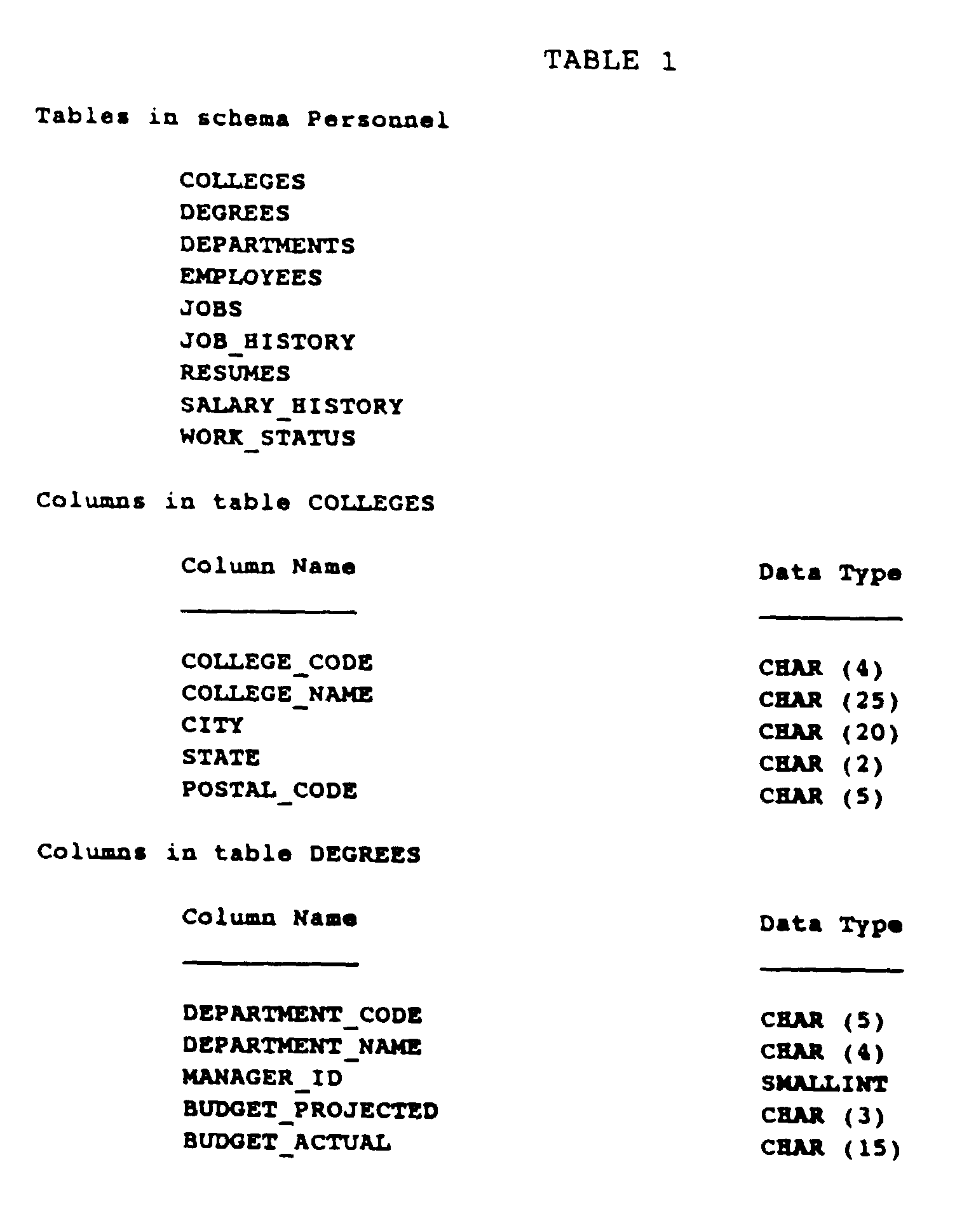


- The
database workload 22 defines database transactions performed on the data entities in the tables and column elements shown above and is described next in connection with an example workload for the personnel database. - The
database workload definition 22, an example of which is shown below in Table 2, describes the expected database operations on the data entities in the tables and column elements defined in thelogical schema 14. In theworkload 22, the operations on the logical schema 14 (i.e., applications, programs, transactions, and requests) are arranged in a hierarchical fashion. That is, an application includes one or more programs; a program includes one or more transactions; and a transaction includes one or more requests. Briefly, then, within this hierarchical structure, theworkload 22 defines which tables of thelogical schema 14 are accessed, how the tables are accessed (access mode, lock mode, and operation), how frequently they are accessed (frequency and cycle), and how important it is that a operation complete in the shortest time possible (importance).


- Access to data entities in a table is defined by several conditions. First, an access mode statement defines the type of operation that a particular column element is the object of, e.g., a READ, WRITE, or UPDATE operation. Second, a lock mode statement defines whether the data entity can be accessed simultaneously by more than one operation, e.g., whether the column element allows SHARED, EXCLUSIVE, or PROTECTED access. For example, data entities in the EMPLOYEES table shown above are accessed by a CHECK_DEPT_INFO transaction which defines all requests for operations on the table as READ ONLY and SHARED. Finally, the column elements by which data entities in a table are usually accessed are specified in requests. For example, in the request DEPTCODE_1 shown in Table 2 the data entities in the table DEPARTMENTS are accessed by the DEPARTMENT_CODE column element.
- The frequency of access to a table is defined by the number of times the data entities in a table are accessed in a particular cycle of time, i.e., the number of times per hour, day, week, month, quarter, or year. If a table is usually accessed by a particular column element, the frequency of access via that element can be very high in a single cycle. For example, the EMPLOYEES table might be accessed by the
EMPLOYEE_ID column element 50 or 100 times a day. On the other hand, if an table is seldom accessed by the contents of a different column element, the frequency of access can be very low in a single cycle. For example, the EMPLOYEE table might be accessed by the ADDRESS_DATA_1 column element only once a week. - The importance of an application, program, or transaction is a ranking on a scale of one to ten which corresponds to how important it is that the operation complete in the shortest time possible. For example, an application might be considered fairly important and rank a score of 8, while a program within the application might be very important and rank a score of 10. In some specific cases, rankings may seem to conflict with one another. For example, a transaction that looks up an employee's phone number and is performed many times a day, may seem at first to outrank a transaction which looks up an employee's address for payroll processing once a week. However, the payroll processing is likely considered a transaction which outranks other transactions and so requires a higher rating.
- Generally, the importance ratings determine several details of the
final storage schema 38, e.g., the critical access paths in the schema. Thus, by carefully selecting an importance for each application, program, and transaction, a user can create aworkload definition 22 that identifies which aspects of the database design to optimize. A description of each type of operation on the logical schema, i.e., application, program, transaction, and request, follows. - An application is a collection of programs that perform a distinct business function. For example, the "EMPLOYEES" application shown in Table 2 above retrieves and updates information about a company's employees, via individual programs such as "JOBINFO." Note that applications are typically not defined by an access mode, lock mode, frequency, or cycle since they are merely a means for grouping related programs. However, the importance of the application is defined, specifically, as a function of the importance of the programs within the application. For example, the EMPLOYEES application is rated at 8.
- Next, a program, e.g., JOBINFO, is a collection of transactions which performs a specific function or task. The
workload 22 defines s separate program for each executable image or command procedure that accesses the database, e.g., application programs, or VAX Datatrieve, SQL, or DBQ procedures. Within each application, the frequency, cycle, and importance for each program is defined. For example, the cycle of the JOBINFO program is defined as DAILY, its frequency is 80.00, and its importance is 10. - Next, a transaction is a recoverable unit of database activity. For example, JOBINFO includes the transactions CHECK_DEPT_INFO, CHECK_EMPLOYEE_EXISTENCE, and CHECK_JOB_INFO. The access mode for the CHECK_DEPT_INFO transaction is defined as READ ONLY, the lock mode is SHARED, the frequency is 1.00, and the importance is 10. Note that all transactions have the same cycle, i.e., one execution of the program.
- Finally, each transaction is a collection of requests, i.e., single database accesses. Each access is written in a database language such as SQL or DML. For example, referring again to Table 2, the first request in the CHECK_DEPT_INFO transaction is the "DEPTCODE_1" request which is defined by the SQL statement: "SELECT column_list FROM DEPARTMENTS WHERE DEPARTMENT_CODE = "literal" AND JOB_END > "literal".
- The
workload definition 22 as defined above is input to thephysical database designer 36 and analyzed by an expert system to create an optimal physical design. A description of the analysis done by the expert system on theworkload 22 is presented below. - The analysis and characterization of the
workload 22 is the first step in the design process once all of the design inputs have been obtained. The analysis includes the steps of annualizing the frequencies based on processing cycle, normalizing the frequencies for the transactions and requests, and creating an absolute importance for each request. - The expert system within the
physical database designer 36 contains a module KB_ANALYSIS which performs several operations on the workload data in order to determine certain details of the improved database design, i.e., thefinal storage structure 38. First, KB_ANALYSIS "annualizes" the occurrences of each request in theworkload definition 22. That is, it converts the number of occurrences from the number of occurrences per cycle to the number of occurrences per year. For example, if the cycle is hourly, KB_ANALYSIS annualizes the number of occurrences by multiplying hours per day * days per week * weeks per month * months per quarter * quarters per year. - Second, KB_ANALYSIS "normalizes" the occurrences of transactions and requests so that the execution counts can be accurately compared. To do this, KB_ANALYSIS first updates the absolute count of transactions by multiplying the execution count of transactions by the execution count of programs and assigning the result to the absolute count of transactions. Then, KB_ANALYSIS updates the absolute number of requests by multiplying the absolute count of transactions by the execution count of requests and assigning the result to the absolute number of requests.
- Third, KB_ANALYSIS normalizes the importance rating of the requests so that the ratings of all requests in the workload can be accurately compared. That is, the importance of each request is calculated based on the importance of the application, program, and transaction in which the request occurs. To calculate the relative importance of each request, KB_ANALYSIS uses the following algorithm:

- importance high bound =
- application multiplier +
program multiplier +
transaction multiplier +
request multiplier + 1 - request importance =
- application importance * application multiplier +
program importance * program multiplier +
transaction importance * transaction multiplier +
request importance * request multiplier - application multiplier =
- 10**3 = 1000
- program multiplier =
- 10**2 = 100
- transaction multiplier =
- 10**1 = 10
- request multiplier =
- 10**0 = 1
- Finally, KB_ANALYSIS combines the requests of all transactions in the
workload definition 22 into one access path to each data entity for every type of access defined in the workload. To do this, KB_ANALYSIS sorts all requests in a particular order, e.g., by each "break" in the sort order, i.e., by design, retrieval_mode, verb, adverb, object, select_type, or select_object. KB_ANALYSIS also sums the importance at each break in the sort order. - The
data volume definition 28 of Fig. 1 describes the amount of data in the database. Thesystem 10 uses this information in several ways, e.g., to optimize the size and number of database files, areas within the files. Briefly, the data volume is defined as the minimum, average, and maximum number of occurrences of each table and column element, as well as the volatility of the tables and elements. For example, an employee database might contain one EMPLOYEES table for all employees in a company. Therefore, the minimum number of occurrences of data entities in the EMPLOYEES table is equal to the number of employees. Over time, however, the number of employees can vary. This variance is accounted for in the average and maximum number of occurrences of data entities in the EMPLOYEES table. For example, if the company expects to double its number of employees, the average and maximum numbers of entities in the EMPLOYEES table is increased in the data volume definition. - Further, because few databases contain static data, i.e., unchanging data, the system allows users to rate the volatility of each table and column element on a scale of one to ten (one for very stable and ten for very volatile). For example, the number of entities in the EMPLOYEES table can be somewhat volatile, e.g., subject to many additions and deletions, and receive a rating of 8. On the other hand, the number of entities in the COLLEGES table, for example, may be quite stable and receive a rating of 2. If the number of entities in a table is likely to change no more or no less than the number of other entities in the database, the table is or column element is typically assigned a volatility rating of 5.
- Table 3 below shows an example volume definition for the personnel database. The overall definition is assigned default values of zero occurrences and a middle range volatility rating of 5. Likewise, each table and column entry is assigned values to indicate the number of occurrences of entities in the table or column and its volatility. For example, the number of occurrences of data entities in the COLLEGES table has a minimum, average, and maximum value of 16, and a volatility of 5.


- The final input to the
physical database designer 36, i.e., thedesign constraints definition 34 is described below. - The
design constraints definition 34 of Fig. 1 describes the constraints on the physical resources used by the database, and is used to help create thestorage schema 38. Briefly, the constraints include the maximum number of users permitted to access the database at one time, the number of storage devices available to store files associated with the database, the maximum amount of space available on any one of the devices, the maximum amount of memory available to applications using the database (roughly half the amount of free memory), and the percentage of available memory to be used by applications. For example, if two thirds of the available system memory is to be used by the database applications, the available memory is 67%. - As an example, Table 4 below shows design constraint definition for the personnel database. The number of storage devices, i.e., disks, is 10 and provides 100,000 blocks of disk storage for 50 users. The maximum amount of memory available to applications is 64 megabytes, and the applications actually use 96% of the available memory.
-
- Environment for physical_design physical;
- Disks is 10;
- Area_size is 100000 blocks;
- Users is 50;
- Maximum_memory is 64 megabytes;
- Available_memory is 96 percent;
- Fig. 2 is a flow chart which illustrates the steps of entering the design inputs, i.e., the
logical schema 14, theworkload 22, the constraints, 34, and thedata volume 28. First, thephysical database designer 36, creates a physical design into which it will store the results of its work. To initiate this process, thedesigner 36 prompts the user for the file name of alogical schema 14 andworkload 22 to use as inputs to the design process (step 100). Next, thedesigner 36 creates an instance of the logical schema 14 (step 102) and checks to see that the schema is unique (step 104), i.e., that there are no other instances of the same logical schema and only one logical schema for the physical design. If theschema 14 is not unique, thedesigner 36 returns an error (step 106). Otherwise, i.e., if theschema 14 is unique, thedesigner 36 creates instances for each table and column element in the schema (step 108). - In the next processing phase, the
designer 36 creates volume instances for each table and column element in the logical schema (step 112). Thedesigner 36 next creates a instance of the workload 22 (step 114) and checks to see that the workload is unique (step 116), i.e., that there is one workload only for the physical design. If theworkload 22 is not unique, thedesigner 36 returns an error (step 118). Otherwise, i.e., if theworkload 22 is unique, thedesigner 36 creates an instance for each request, transaction, program, and application in the workload 22 (step 120). Finally, thedesigner 36 validates each request instance against the table and column element instances for the logical schema and prompts the user to resolve any inconsistencies (step 122). - Having described the inputs to the
designer 36, we next describe the outputs from thedesigner 36. - The
runtime parameters 42 andcreation parameters 44 of Fig. 1 are contained in a command procedure, e.g., a series of Digital Command Language (DCL) commands, which the user can use to implement the improved database. That is, when the command procedure is run, it unloads the data entities from an existing database, optimizes the physical design of the database, and reloads the data entities into a new database built upon the optimized design. Table 5 below shows an example file of a command procedure used to optimize the personnel database. - Briefly, the command procedure shown in Table 5 (supplied in Appendix B) provides the user with information regarding the optimization process it is undertaking and allows the user an opportunity to change the input to various steps in the process. For example, if the database has tables of data entities which depend upon one another, i.e., have matching records in them, then the procedure prompts the user to edit a load sequence so that the tables are loaded in the proper order. Next, the procedure instructs the user as to what is necessary to implement the new database, e.g., a logical schema and enough space to temporarily store the data found in the tables of the existing database. And finally, the procedure informs the user as to how the storage of the data entities has been optimized and offers the user an opportunity to change the optimization.
- Once the procedure has provided the user with a description of how the database will be changed, it proceeds to unload the data entities from the existing database. After the data entities are unloaded, the procedure defines the new database, creates storage areas according to the
storage schema 38, and creates storage maps for tables, i.e., mapping of the tables to areas of the database. Once the new database is complete, the procedure sorts the unloaded data entities from the old database, and loads the sorted data entities into the new database. The process followed by the command procedure in theruntime parameters 42 and thecreation parameters 44 can be further documented in various textual reports. - Fig. 3 is a flow chart illustrating steps which an expert system in concert with the
designer 36 takes in order to generate an optimal physical design. First, thedesigner 36 analyzes the applications, programs, transactions and requests to determine the access entries to each data entity (step 302). Having analyzed the necessary aspects of each data entity, thedesigner 36 next retrieves the importance for each request in the transaction and program (step 304) and determines the critical access to each data entity (step 306). - In the next phase of processing, the
designer 36 analyzes the critical access methods entries to determine the desired access mode and access field for each data entity (step 308). Having completed its analysis, thedesigner 36, then creates access method instances for each unique critical access and data entity combination (step 310). Followingstep 310, thedesigner 36 analyzes the critical access entries to determine placement instance for each data entity (step 312). The designer also analyzes transaction instances (for relational databases) or relationship instances (for CODASYL databases) and request instances to determine the interrelationships between data entities (step 314). Once the analysis is complete, thedesigner 36, generates clusters for interrelated data entities (step 316). - Then, in the final phase of processing, the
designer 36 analyzes clusters to determine the mapping of entities to storage areas and storage maps (step 318) and creates instances of storage areas, storage maps, storage partitions, and storage indices (step 320). Once the instances are created, thedesigner 36 uses the access methods to determine storage index (step 322) and also uses the clusters and placements to determine storage area and storage map (step 324). Finally, thedesigner 36 prompts the user to determine the storage partitions (step 326) and creates load sequence instances using the volume, request, cluster, and storage map instances (step 328). - Fig. 4 is a flow chart illustrating the steps of producing the
logical schema 40, thestorage schema 38, and thecreation parameters 44 andruntime parameters 42. First, thedesigner 36 creates the newlogical schema 40. To do this, the designer accesses instances of the logical schema, data entities, attributes, and relationships to create model specific Data Definition Language (DDL) file (step 400). Second, thedesigner 36 creates thestorage schema 38. To do this, thedesigner 36 accesses instances of the record format, storage schema, storage area, storage map, storage index, and storage partition to create model specific DDL file (step 402). Third, thedesigner 36 creates thecreation parameters 44. To do this, thedesigner 36 accesses instances of the storage area, implementation product, and design constraints to create model specific creation commands (step 404). Fourth, the designer creates theruntime parameters 42. To do this, thedesigner 36 accesses instances of the implementation product, design constraints, storage area, and storage map to create model specific runtime commands (step 406). - And finally, the
designer 36 creates various textual reports such as a design report. To do this, thedesigner 36 accesses instances of logical schema, access method, placement, cluster, storage schema, storage area, storage map, and load sequence and writes descriptions of each to the report (step 410). The design report 48, is useful, for example, in explaining to a user why thesystem 10 chose the parameters and schema characteristics it did. The report is also useful in determining if the system used the appropriate inputs to generate thestorage schema 38. - The source code for the physical database designer (supplied in Appendix C and incorporated herein by reference) embodies the software modules described above. The programming languages used are VAX C version 3.0-031. The computer used is a VAX 8820 and the operating system used is VAX/VMS version 5.2. The modules are intended to run under DECwindows, but can also run under a DCL command line interface. Also a list of database design rules and heuristics coded in the relational data manipulation language, e.g., VAX SQL, is included in Appendix A.
- This disclosure contains material which is subject to copyright protection. The copyright owner does not object to the facsimile reproduction of the patent document as it appears in the US Patent and Trademark Office files, but reserves all other copyright rights.
- Other embodiments are within the following claims.
Claims (17)
- A method for enabling a computer system to generate a physical database design, the database to include data records and index records, the index records to access data stored in the data records, comprising the steps of:retrieving a set of expert rules (36) from a memory of the computer system;accepting a logical schema (14) as input, said logical schema to describe a logical arrangement of the database;accepting a data volume definition (28) as input, said data volume definition to describe an amount of data to be stored in the database;defining a plurality of first operations, each first operation of said plurality of first operations to access the data of the database;accepting a first workload description (22) as input, said first workload description to specify a first workload for each first operation of said plurality of first operations;grouping selected first operations of said plurality of first operations into a plurality of second operations, each second operation including at least one first operation, and each first operation being grouped in at least one second operation;accepting a second workload description (22) as input, said second workload description to specify a second workload for each second operation of said plurality of second operations;grouping selected second operations of said plurality of second operations into a plurality of third operations, each third operation including at least one second operation, and each second operation being grouped in at least one third operation;accepting a third workload description (22) as input, said third workload description to specify a third workload for each third operation of said plurality of third operations;selectively applying said set of expert rules to said logical schema (14) and said data volume description (28) and said first workload description (22) and said second workload description (22) and said third workload description (22) to generate the physical design of the database (38), the physical design to specify how the data will be physically stored in the data records and how the data records are accessed by the index records.
- The method of claim 1 wherein each third operation is a computer program, each second operation is a recoverable database transaction, and said plurality of third operations include data read operations, data write operations, and data update operations.
- The method of claim 1 wherein
said first workload description (22), said second workload description (22) and said third workload description (22) further comprise a relative importance and relative frequency of said first, second and third operations,
the process further comprising:annualizing said relative frequencies of said first, second and third operations; andderiving, after annualizing, an absolute importance and an absolute frequency of said first operations. - The method of claim 1 further comprising the steps of:grouping selected third operations of said plurality of third operations into a plurality of fourth operations, each fourth operation of said plurality of fourth operations including at least one third operation; andaccepting a fourth workload description (22) as input, said fourth workload description to specify a fourth workload for each fourth operation of said plurality of fourth operations.
- The method of claim 1 wherein the steps of accepting said first workload description, said second workload description and said third workload description further comprise the steps of:
entering an output of an event performance collector (26). - The method of claim 1 wherein the first, second and third workload descriptions includes the frequency of operations at different levels of the hierarchy of first, second and third operations.
- The method of claim 1 wherein the second workload description includes the access mode of transactions.
- The method of claim 1 wherein the second workload description includes the lock mode of transactions.
- The method of claim 1 wherein the physical database design is a relational database or a codasyl database.
- The method of claim 1 wherein the data volume definition (28) comprises information on a number of occurrences of the data records.
- The method of claim 10 wherein the data volume definition (28) comprises information on the volatility of the number of occurrences.
- The method of claim 11 wherein the data volume definition (28) comprises, for operations performed on entities in the database, information on the minimum number of occurrences, the maximum number of occurrences and the average number of occurrences.
- The method of claim 1 further comprising the steps of:accepting as input a physical constraints definition (34) for the database; andusing the physical constraints definition in applying the expert rules to generate the physical database design.
- The method of claim 13 wherein the physical constraints definition (34) includes the size of main memory available to the database.
- The method of claim 14 wherein the physical constraints definition (34) includes the size of disk memories on which records in the database are to be stored.
- The method of claim 15 wherein the physical constraints definition (34) includes the maximum number of concurrent users to the database.
- The method of claim 1 wherein at least part of the workload descriptions (22) are entered by translating a program written in a known database language.
Applications Claiming Priority (2)
| Application Number | Priority Date | Filing Date | Title |
|---|---|---|---|
| US48537690A | 1990-02-26 | 1990-02-26 | |
| US485376 | 1990-02-26 |
Publications (3)
| Publication Number | Publication Date |
|---|---|
| EP0444364A2 EP0444364A2 (en) | 1991-09-04 |
| EP0444364A3 EP0444364A3 (en) | 1992-12-23 |
| EP0444364B1 true EP0444364B1 (en) | 1997-07-09 |
Family
ID=23927915
Family Applications (1)
| Application Number | Title | Priority Date | Filing Date |
|---|---|---|---|
| EP90314392A Expired - Lifetime EP0444364B1 (en) | 1990-02-26 | 1990-12-28 | Physical database design system |
Country Status (5)
| Country | Link |
|---|---|
| US (1) | US5485610A (en) |
| EP (1) | EP0444364B1 (en) |
| JP (1) | JP2768433B2 (en) |
| CA (1) | CA2037021C (en) |
| DE (1) | DE69031028T2 (en) |
Families Citing this family (45)
| Publication number | Priority date | Publication date | Assignee | Title |
|---|---|---|---|---|
| US6003033A (en) * | 1992-02-28 | 1999-12-14 | International Business Machines Corporation | System and method for describing and creating a user defined arbitrary data structure corresponding to a tree in a computer memory |
| US5717918A (en) * | 1994-06-17 | 1998-02-10 | Hitachi, Ltd. | Method for concurrently performing a physical sequential scan of a database into a database buffer which is queued until a preceding scan is completed |
| US5625811A (en) * | 1994-10-31 | 1997-04-29 | International Business Machines Corporation | Method and system for database load balancing |
| US5774714A (en) * | 1995-03-27 | 1998-06-30 | Hewlett-Packard Company | Zone bit recording enhanced video data layout |
| US5675731A (en) * | 1995-09-22 | 1997-10-07 | Sun Microsystems, Inc. | Scatter load for system test |
| US7349892B1 (en) | 1996-05-10 | 2008-03-25 | Aol Llc | System and method for automatically organizing and classifying businesses on the World-Wide Web |
| US6148289A (en) | 1996-05-10 | 2000-11-14 | Localeyes Corporation | System and method for geographically organizing and classifying businesses on the world-wide web |
| US5778393A (en) * | 1996-05-20 | 1998-07-07 | International Business Machines Corporation | Adaptive multitasking for dataset storage |
| EP0972247B1 (en) * | 1996-08-02 | 2004-03-17 | Hewlett-Packard Company | Method and apparatus for allowing distributed control of shared resources |
| US6317737B1 (en) * | 1996-10-18 | 2001-11-13 | Sagent Technologies, Inc. | Data descriptions in a database system |
| US6016394A (en) * | 1997-09-17 | 2000-01-18 | Tenfold Corporation | Method and system for database application software creation requiring minimal programming |
| US6477571B1 (en) * | 1998-08-11 | 2002-11-05 | Computer Associates Think, Inc. | Transaction recognition and prediction using regular expressions |
| US6487547B1 (en) | 1999-01-29 | 2002-11-26 | Oracle Corporation | Database appliance comprising hardware and software bundle configured for specific database applications |
| US6865576B1 (en) * | 1999-05-21 | 2005-03-08 | International Business Machines Corporation | Efficient schema for storing multi-value attributes in a directory service backing store |
| US6490590B1 (en) * | 2000-02-14 | 2002-12-03 | Ncr Corporation | Method of generating a logical data model, physical data model, extraction routines and load routines |
| US6898783B1 (en) * | 2000-08-03 | 2005-05-24 | International Business Machines Corporation | Object oriented based methodology for modeling business functionality for enabling implementation in a web based environment |
| US6684388B1 (en) | 2000-08-22 | 2004-01-27 | International Business Machines Corporation | Method for generating platform independent, language specific computer code |
| US7171455B1 (en) | 2000-08-22 | 2007-01-30 | International Business Machines Corporation | Object oriented based, business class methodology for generating quasi-static web pages at periodic intervals |
| US6853994B1 (en) * | 2000-08-30 | 2005-02-08 | International Business Machines Corporation | Object oriented based, business class methodology for performing data metric analysis |
| US7536686B2 (en) * | 2000-09-08 | 2009-05-19 | Oracle International Corporation | Techniques for automatically installing and configuring database applications |
| US6694325B2 (en) * | 2000-10-16 | 2004-02-17 | Frank Jas | Database method implementing attribute refinement model |
| US6823342B2 (en) * | 2001-05-15 | 2004-11-23 | Vykor, Inc. | Method and system for capturing, managing, and disseminating manufacturing knowledge |
| US7134122B1 (en) | 2001-05-31 | 2006-11-07 | Oracle International Corporation | One click deployment |
| US6978282B1 (en) * | 2001-09-04 | 2005-12-20 | Emc Corporation | Information replication system having automated replication storage |
| US7243108B1 (en) * | 2001-10-14 | 2007-07-10 | Frank Jas | Database component packet manager |
| US6920460B1 (en) | 2002-05-29 | 2005-07-19 | Oracle International Corporation | Systems and methods for managing partitioned indexes that are created and maintained by user-defined indexing schemes |
| US20050038786A1 (en) * | 2003-08-11 | 2005-02-17 | International Business Machines Corporation (Ibm) | Self-configuration of database tables |
| KR100645513B1 (en) * | 2004-10-15 | 2006-11-15 | 삼성전자주식회사 | Performance Management Data Processor for single table and Method thereof |
| US7437080B2 (en) * | 2005-02-03 | 2008-10-14 | Stratalight Communications, Inc. | Optical transmission system having optimized filter wavelength offsets |
| US7447681B2 (en) | 2005-02-17 | 2008-11-04 | International Business Machines Corporation | Method, system and program for selection of database characteristics |
| US20070174346A1 (en) * | 2006-01-18 | 2007-07-26 | Brown Douglas P | Closed-loop validator |
| US7805443B2 (en) * | 2006-01-20 | 2010-09-28 | Microsoft Corporation | Database configuration analysis |
| US7685145B2 (en) * | 2006-03-28 | 2010-03-23 | Microsoft Corporation | Database physical design refinement using a merge-reduce approach |
| US7580941B2 (en) * | 2006-06-13 | 2009-08-25 | Microsoft Corporation | Automated logical database design tuning |
| US20080183764A1 (en) * | 2007-01-31 | 2008-07-31 | Microsoft Corporation | Continuous physical design tuning |
| US8150790B2 (en) * | 2007-01-31 | 2012-04-03 | Microsoft Corporation | Lightweight physical design alerter |
| US9805077B2 (en) * | 2008-02-19 | 2017-10-31 | International Business Machines Corporation | Method and system for optimizing data access in a database using multi-class objects |
| US8140548B2 (en) | 2008-08-13 | 2012-03-20 | Microsoft Corporation | Constrained physical design tuning |
| US20100114976A1 (en) * | 2008-10-21 | 2010-05-06 | Castellanos Maria G | Method For Database Design |
| US8566318B1 (en) * | 2010-09-10 | 2013-10-22 | Giovanni Sacco | Process for physical database design based on transaction workload |
| US8949293B2 (en) | 2010-12-17 | 2015-02-03 | Microsoft Corporation | Automatically matching data sets with storage components |
| US9176902B1 (en) * | 2012-06-27 | 2015-11-03 | Emc Corporation | Data migration techniques |
| US9639562B2 (en) * | 2013-03-15 | 2017-05-02 | Oracle International Corporation | Automatically determining an optimal database subsection |
| US10466936B2 (en) * | 2014-09-26 | 2019-11-05 | Oracle International Corporation | Scalable, multi-dimensional search for optimal configuration |
| JP6148763B2 (en) * | 2015-06-15 | 2017-06-14 | 株式会社日立製作所 | Method for grouping data records into a data store across network nodes to optimize data access |
Family Cites Families (7)
| Publication number | Priority date | Publication date | Assignee | Title |
|---|---|---|---|---|
| US4468732A (en) * | 1975-12-31 | 1984-08-28 | International Business Machines Corporation | Automated logical file design system with reduced data base redundancy |
| US4631664A (en) * | 1983-07-19 | 1986-12-23 | Bachman Information Systems, Inc. | Partnership data base management system and method |
| JPS6077249A (en) * | 1983-10-04 | 1985-05-01 | Nec Corp | Automatic formation device of data structure |
| JP2602205B2 (en) * | 1986-01-16 | 1997-04-23 | 株式会社日立製作所 | Database access control method |
| US4956774A (en) * | 1988-09-02 | 1990-09-11 | International Business Machines Corporation | Data base optimizer using most frequency values statistics |
| US5014197A (en) * | 1988-09-02 | 1991-05-07 | International Business Machines Corporation | Assignment of files to storage device using macro and micro programming model which optimized performance of input/output subsystem |
| US5159687A (en) * | 1989-11-14 | 1992-10-27 | Caseworks, Inc. | Method and apparatus for generating program code files |
-
1990
- 1990-12-28 EP EP90314392A patent/EP0444364B1/en not_active Expired - Lifetime
- 1990-12-28 DE DE69031028T patent/DE69031028T2/en not_active Expired - Lifetime
-
1991
- 1991-02-22 JP JP3028360A patent/JP2768433B2/en not_active Expired - Lifetime
- 1991-02-25 CA CA002037021A patent/CA2037021C/en not_active Expired - Lifetime
-
1994
- 1994-08-19 US US08/292,575 patent/US5485610A/en not_active Expired - Lifetime
Also Published As
| Publication number | Publication date |
|---|---|
| CA2037021C (en) | 1995-08-01 |
| JPH04217042A (en) | 1992-08-07 |
| US5485610A (en) | 1996-01-16 |
| DE69031028D1 (en) | 1997-08-14 |
| JP2768433B2 (en) | 1998-06-25 |
| EP0444364A3 (en) | 1992-12-23 |
| DE69031028T2 (en) | 1997-11-20 |
| EP0444364A2 (en) | 1991-09-04 |
Similar Documents
| Publication | Publication Date | Title |
|---|---|---|
| EP0444364B1 (en) | Physical database design system | |
| US6374252B1 (en) | Modeling of object-oriented database structures, translation to relational database structures, and dynamic searches thereon | |
| US6789071B1 (en) | Method for efficient query execution using dynamic queries in database environments | |
| US7409385B2 (en) | Method, system and program for executing a query having a UNION operator | |
| Sanders et al. | Denormalization effects on performance of RDBMS | |
| Muralikrishna et al. | Equi-depth multidimensional histograms | |
| US7672926B2 (en) | Method and system for updating value correlation optimizations | |
| US7539667B2 (en) | Method, system and program for executing a query having a union operator | |
| US5758144A (en) | Database execution cost and system performance estimator | |
| EP0801773B1 (en) | Storage plane organization and storage systems based thereon | |
| US6681218B1 (en) | System for managing RDBM fragmentations | |
| EP0633538A2 (en) | Relational database management system | |
| US20030088579A1 (en) | Collecting statistics in a database system | |
| US8108431B1 (en) | Two-dimensional data storage system | |
| US20040260671A1 (en) | Dimension-based partitioned cube | |
| Dinter et al. | The OLAP market: state of the art and research issues | |
| US5884311A (en) | Method and system for dynamically configuring a relational database | |
| Riedewald et al. | pCube: Update-efficient online aggregation with progressive feedback and error bounds | |
| US7213014B2 (en) | Apparatus and method for using a predefined database operation as a data source for a different database operation | |
| US20050114404A1 (en) | Database table version upload | |
| US20060085464A1 (en) | Method and system for providing referential integrity constraints | |
| US20080215539A1 (en) | Data ordering for derived columns in a database system | |
| Kraft et al. | Coarse-grained optimization: Techniques for rewriting sql statement sequences | |
| Leymann | UDH: A universal relation system | |
| Ling et al. | Extending classical functional dependencies for physical database design |
Legal Events
| Date | Code | Title | Description |
|---|---|---|---|
| PUAI | Public reference made under article 153(3) epc to a published international application that has entered the european phase |
Free format text: ORIGINAL CODE: 0009012 |
|
| 17P | Request for examination filed |
Effective date: 19910102 |
|
| AK | Designated contracting states |
Kind code of ref document: A2 Designated state(s): DE FR GB IT |
|
| PUAL | Search report despatched |
Free format text: ORIGINAL CODE: 0009013 |
|
| AK | Designated contracting states |
Kind code of ref document: A3 Designated state(s): DE FR GB IT |
|
| RAP1 | Party data changed (applicant data changed or rights of an application transferred) |
Owner name: QUANTUM CORPORATION |
|
| RAP1 | Party data changed (applicant data changed or rights of an application transferred) |
Owner name: DIGITAL EQUIPMENT CORPORATION |
|
| 17Q | First examination report despatched |
Effective date: 19960423 |
|
| RAP1 | Party data changed (applicant data changed or rights of an application transferred) |
Owner name: ORACLE CORPORATION |
|
| GRAG | Despatch of communication of intention to grant |
Free format text: ORIGINAL CODE: EPIDOS AGRA |
|
| GRAH | Despatch of communication of intention to grant a patent |
Free format text: ORIGINAL CODE: EPIDOS IGRA |
|
| GRAH | Despatch of communication of intention to grant a patent |
Free format text: ORIGINAL CODE: EPIDOS IGRA |
|
| GRAA | (expected) grant |
Free format text: ORIGINAL CODE: 0009210 |
|
| AK | Designated contracting states |
Kind code of ref document: B1 Designated state(s): DE FR GB IT |
|
| REF | Corresponds to: |
Ref document number: 69031028 Country of ref document: DE Date of ref document: 19970814 |
|
| ET | Fr: translation filed | ||
| PLBE | No opposition filed within time limit |
Free format text: ORIGINAL CODE: 0009261 |
|
| STAA | Information on the status of an ep patent application or granted ep patent |
Free format text: STATUS: NO OPPOSITION FILED WITHIN TIME LIMIT |
|
| 26N | No opposition filed | ||
| REG | Reference to a national code |
Ref country code: GB Ref legal event code: IF02 |
|
| REG | Reference to a national code |
Ref country code: GB Ref legal event code: 732E |
|
| REG | Reference to a national code |
Ref country code: FR Ref legal event code: TP |
|
| PGFP | Annual fee paid to national office [announced via postgrant information from national office to epo] |
Ref country code: GB Payment date: 20091021 Year of fee payment: 20 Ref country code: FR Payment date: 20091203 Year of fee payment: 20 |
|
| PGFP | Annual fee paid to national office [announced via postgrant information from national office to epo] |
Ref country code: DE Payment date: 20091125 Year of fee payment: 20 |
|
| REG | Reference to a national code |
Ref country code: GB Ref legal event code: PE20 Expiry date: 20101227 |
|
| PG25 | Lapsed in a contracting state [announced via postgrant information from national office to epo] |
Ref country code: GB Free format text: LAPSE BECAUSE OF EXPIRATION OF PROTECTION Effective date: 20101227 |
|
| PGFP | Annual fee paid to national office [announced via postgrant information from national office to epo] |
Ref country code: IT Payment date: 20091209 Year of fee payment: 20 |
|
| PG25 | Lapsed in a contracting state [announced via postgrant information from national office to epo] |
Ref country code: DE Free format text: LAPSE BECAUSE OF EXPIRATION OF PROTECTION Effective date: 20101228 |