EP0444359B1 - Dynamic flood conveyor with weir - Google Patents
Dynamic flood conveyor with weir Download PDFInfo
- Publication number
- EP0444359B1 EP0444359B1 EP90314259A EP90314259A EP0444359B1 EP 0444359 B1 EP0444359 B1 EP 0444359B1 EP 90314259 A EP90314259 A EP 90314259A EP 90314259 A EP90314259 A EP 90314259A EP 0444359 B1 EP0444359 B1 EP 0444359B1
- Authority
- EP
- European Patent Office
- Prior art keywords
- roller
- fluid
- segments
- fluid containment
- rollers
- Prior art date
- Legal status (The legal status is an assumption and is not a legal conclusion. Google has not performed a legal analysis and makes no representation as to the accuracy of the status listed.)
- Expired - Lifetime
Links
- 239000012530 fluid Substances 0.000 claims description 106
- 239000000758 substrate Substances 0.000 claims description 25
- 238000006073 displacement reaction Methods 0.000 claims description 3
- 239000000463 material Substances 0.000 description 18
- 239000007788 liquid Substances 0.000 description 9
- 239000000126 substance Substances 0.000 description 9
- 239000006260 foam Substances 0.000 description 7
- 230000015572 biosynthetic process Effects 0.000 description 4
- 238000010276 construction Methods 0.000 description 2
- 230000003993 interaction Effects 0.000 description 2
- 239000004094 surface-active agent Substances 0.000 description 2
- 241001665400 Coracias abyssinicus Species 0.000 description 1
- 238000006243 chemical reaction Methods 0.000 description 1
- 230000000694 effects Effects 0.000 description 1
- 230000005484 gravity Effects 0.000 description 1
- 230000004941 influx Effects 0.000 description 1
- 230000002093 peripheral effect Effects 0.000 description 1
- 230000000284 resting effect Effects 0.000 description 1
- 230000000630 rising effect Effects 0.000 description 1
- 239000007921 spray Substances 0.000 description 1
Images



Classifications
-
- C—CHEMISTRY; METALLURGY
- C23—COATING METALLIC MATERIAL; COATING MATERIAL WITH METALLIC MATERIAL; CHEMICAL SURFACE TREATMENT; DIFFUSION TREATMENT OF METALLIC MATERIAL; COATING BY VACUUM EVAPORATION, BY SPUTTERING, BY ION IMPLANTATION OR BY CHEMICAL VAPOUR DEPOSITION, IN GENERAL; INHIBITING CORROSION OF METALLIC MATERIAL OR INCRUSTATION IN GENERAL
- C23F—NON-MECHANICAL REMOVAL OF METALLIC MATERIAL FROM SURFACE; INHIBITING CORROSION OF METALLIC MATERIAL OR INCRUSTATION IN GENERAL; MULTI-STEP PROCESSES FOR SURFACE TREATMENT OF METALLIC MATERIAL INVOLVING AT LEAST ONE PROCESS PROVIDED FOR IN CLASS C23 AND AT LEAST ONE PROCESS COVERED BY SUBCLASS C21D OR C22F OR CLASS C25
- C23F1/00—Etching metallic material by chemical means
- C23F1/08—Apparatus, e.g. for photomechanical printing surfaces
-
- B—PERFORMING OPERATIONS; TRANSPORTING
- B65—CONVEYING; PACKING; STORING; HANDLING THIN OR FILAMENTARY MATERIAL
- B65G—TRANSPORT OR STORAGE DEVICES, e.g. CONVEYORS FOR LOADING OR TIPPING, SHOP CONVEYOR SYSTEMS OR PNEUMATIC TUBE CONVEYORS
- B65G49/00—Conveying systems characterised by their application for specified purposes not otherwise provided for
- B65G49/02—Conveying systems characterised by their application for specified purposes not otherwise provided for for conveying workpieces through baths of liquid
- B65G49/04—Conveying systems characterised by their application for specified purposes not otherwise provided for for conveying workpieces through baths of liquid the workpieces being immersed and withdrawn by movement in a vertical direction
- B65G49/0409—Conveying systems characterised by their application for specified purposes not otherwise provided for for conveying workpieces through baths of liquid the workpieces being immersed and withdrawn by movement in a vertical direction specially adapted for workpieces of definite length
- B65G49/0413—Conveying systems characterised by their application for specified purposes not otherwise provided for for conveying workpieces through baths of liquid the workpieces being immersed and withdrawn by movement in a vertical direction specially adapted for workpieces of definite length arrangements for conveyance through the bath
-
- H—ELECTRICITY
- H05—ELECTRIC TECHNIQUES NOT OTHERWISE PROVIDED FOR
- H05K—PRINTED CIRCUITS; CASINGS OR CONSTRUCTIONAL DETAILS OF ELECTRIC APPARATUS; MANUFACTURE OF ASSEMBLAGES OF ELECTRICAL COMPONENTS
- H05K3/00—Apparatus or processes for manufacturing printed circuits
- H05K3/0085—Apparatus for treatments of printed circuits with liquids not provided for in groups H05K3/02 - H05K3/46; conveyors and holding means therefor
-
- Y—GENERAL TAGGING OF NEW TECHNOLOGICAL DEVELOPMENTS; GENERAL TAGGING OF CROSS-SECTIONAL TECHNOLOGIES SPANNING OVER SEVERAL SECTIONS OF THE IPC; TECHNICAL SUBJECTS COVERED BY FORMER USPC CROSS-REFERENCE ART COLLECTIONS [XRACs] AND DIGESTS
- Y10—TECHNICAL SUBJECTS COVERED BY FORMER USPC
- Y10S—TECHNICAL SUBJECTS COVERED BY FORMER USPC CROSS-REFERENCE ART COLLECTIONS [XRACs] AND DIGESTS
- Y10S134/00—Cleaning and liquid contact with solids
- Y10S134/902—Semiconductor wafer
Definitions
- This invention relates to apparatus for applying chemical solutions to the surface of a piece of material.
- the invention relates to apparatus which permits a chemical solution to be applied to the surface of a material such that the solution interacts with the material at a generally uniform rate at each point on the surface of the material.
- the invention relates to apparatus which permits a strip of circuit board substrate being transported by a conventional conveyor system to be totally immersed in a chemical bath which is supplied with a chemical solution by a closed circuit recirculation system.
- the invention relates to apparatus of the type described in which the closed circuit system minimizes the formation of foam in the chemical solution.
- the dynamic flood conveyor described in my U. S. Patent No. 4,724,856 facilitates a uniform chemical reaction rate on a circuit board substrate by totally immersing the substrate in a chemical fluid reservoir or flood.
- Two disadvantages have been identified in utilizing the dynamic flood conveyor.
- Second, the apparatus utilized in connection with the flood conveyor to capture used fluid which escaped from reservoir 43 was not especially well suited to effectively minimize the generation of foam in the used fluid.
- a dynamic flood conveyor for processing the upper surface of a circuit board substrate by moving the substrate through a body of fluid, said substrate having an upper surface, said conveyor including
- the present invention can provide a dynamic flood conveyor apparatus which substantially minimizes fluid loss from the reservoir when a circuit board substrate travels through the reservoir and which collects fluid which leaks from the reservoir and returns the fluid to the reservoir while minimizing or eliminating the formation of foam in the fluid during the collection and return of the fluid.
- the present invention can provide an improved dynamic flood conveyor apparatus for contacting the surfaces of a material with a chemical solution to promote the uniform chemical interaction of the solution at all points on the surface of a piece of material.
- the flood conveyor includes a pair of upstanding spaced apart side walls; generally horizontally oriented adjacent parallel support rollers for supporting and transporting said piece of material, the support rollers including first and second end rollers and a third roller intermediate the end rollers and spanning the space between the side walls, having first and second ends each rotatably mounted in one of the walls, and having a cylindrical outer surface spanning the space between the side walls, the uppermost portion of the cylindrical surface of the rollers each generally lying in and defining a common generally horizontal imaginary plane means for rotating each of the support rollers in a common direction; a plurality of lower fluid containment rollers each sealingly interposed between, continuously contacting and rotating on top of and intermediate the cylindrical surfaces of an adjacent pair of support rollers, and rotating in a direction opposite the common direction of rotation of the support rollers; a pair of upper fluid containment rollers each spanning the space between said side walls, having a pair of ends each rotatably mounted in one of the side walls
- the disk prevents a piece of material passing between the disk and third roller from upwardly rising away from contact with the third roller and, for a piece of material passing between the disk and third roller, exposing to fluid in the reservoir the upper surface of the portion of the piece of material contacting the third roller and not contacting the disk.
- the flood conveyor also includes means for injecting fluid into the reservoir.
- At least one of the upper fluid containment rollers includes a generally horizontally oriented shaft and is segmented into a plurality of cylindrical segments, each of the segments having an aperture formed therethrough which circumscribes the shaft and is shaped and dimensioned to permit the segment to be vertically displaced with respect to the shaft.
- FIGs. 1 and 2 illustrate a dynamic flood conveyor constructed in accordance with the principles of the invention and including upstanding side walls 11 and 12 and parallel support rollers 13 - 18 each having first 19 and second 60 ends rotatably mounted in one of side walls 11 and 12. Rollers 13 and 18 are the end rollers. The diameter of each roller 13-18 presently preferably equals that of the other rollers 13-18. Each roller 13-18 has a cylindrical outer surface 13A-18A. Rollers 13-18 support and transport a strip of material 25 through the dynamic flood conveyor in the direction of arrow A.
- Rollers 13-18 each turn in the direction indicated by arrows B.
- the ends 19 of each adjacent pair of support rollers 13-18 are presently equally spaced apart.
- Each end 19 is rotatably positioned in one of a series of parallel, vertical, spaced apart retainer slots 26 formed in wall 12.
- the width of a slot 26 is uniform along its length and is slightly greater than the outer diameter of a bushing 40 on an end 18.
- each end 60 is rotatably positioned in one of a series of parallel, vertical, spaced apart retainer slots 27 formed in wall 11.
- the width of slot 27 is uniform along its length and is slightly greater than the outer diameter of a bushing 40 on an end 60.
- End 60 of each roller 13-18 carries a chain sprocket 28 fixedly attached thereto.
- a moving chain 29 engages and rotates each sprocket 28 and roller 13-18.
- Wall 11 includes side dam member 30 extending therealong. End 60 of each support roller 13-18 rotatably extends through an aperture 31 formed through side dam 30. Cylindrical low friction plastic washers 32 seal the space between each roller 13-18 and walls 11 and 12.
- Elongate cylindrical lower fluid containment rollers 20-24 are interposed between and continuously contact and rotate on top of and intermediate the outer cylindrical surfaces 13A-18A of each adjacent pair of support rollers 13-18.
- lower fluid containment roller 20 is interposed between surfaces 13A and 14A of roller pair 13, 14.
- Fluid containment rollers 20-24 are rotated in the direction of arrows C by support rollers 13-18.
- Each fluid containment roller 20-24 is presently of a diameter slightly less than that which would cause the roller to protrude above a generally horizontal imaginary plane passing through substrate strip 25, and has a length less than the distance D between side wall 12 and side dam member 30.
- Each roller 20-24 substantially seals the cylindrical outer surfaces of an adjacent support roller 12-18 pair while generally not impeding the free rotation of the roller pair.
- Upper fluid containment rollers 35A and 36A are parallel to one another and are positioned above end rollers 13 and 18.
- the ends of shafts 37 of rollers 35A and 36A are each rotatably mounted in one of side walls 11 and 12.
- Cylindrical low friction plastic washers 53 and 54 seal the spaces between each roller 35, 36 and walls 11 and 12.
- One end of shaft 37 of roller 35A extends into a vertical slot 26 receiving end 19 of roller 13.
- the other end of shaft 37 of roller 35A extends into a vertical slot 27 receiving end 20 of roller 13.
- the diameter of each end of a shaft 37 is presently generally equivalent to the diameter of ends 19 and 60 of rollers 13-18.
- One end of shaft 37 of roller 35A rotatably passes through an aperture formed through side dam member 30 in the same manner as one end of shaft 37 on roller 36A does through aperture 39 in Fig. 2.
- the portions of each end 19, 20, and the ends of shafts 37 in a slot 26, 27 includes a bushing 40 secured thereto.
- One end of shaft 37 of roller 36A extends into vertical slot 26 which receives end 19 of roller 18.
- the other end of shaft 37 of roller 36A also extends into vertical slot 27 which receives end 60 of roller 18.
- End 38 of roller 36A rotatably extends through an aperture 39 formed in side dam 30.
- Rollers 35A and 36A contact rollers 13 and 18 or contact strip 25 passing over rollers 13 and 18.
- Motive power is transmitted from rollers 13 and 18 to rollers 35A, 36A and causes rollers 35A and 36A to turn in the direction indicated by arrow E.
- Disks 41 are fixedly attached to shaft 42.
- the ends of shaft 42 rotatably extend into vertical slots 26 and 27 which rotatably receive ends 19 and 60 of roller 16.
- the end of rod 42 extending into a slot 27 also rotatably passes through an aperture formed through side dam member 30 in the same manner aperture 39 is formed through member 30 for end of roller 36A.
- Disks 41 on shaft 42 contact the outer surface 16A of roller 16 or contact strip 25 traveling over roller 16.
- Motive power is transmitted from roller 16 to friction wheel 54 at the end of shaft 42 carrying disks 41 and causes disks 41 and shaft 42 to turn in the direction indicated by arrow E.
- Disks 41 prevent a strip of material 25 passing through the apparatus of Figs.
- rollers 13-18 From floating upwardly away from the uppermost portions of support rollers 13-18.
- the uppermost portions of rollers 13-18 lie in and define a horizontally oriented imaginary plane.
- strip of material 25 lies in this imaginary plane.
- the imaginary plane is, in Fig. 1, perpendicular to the plane of the paper of the drawings. Since lower fluid containment rollers 20-24 rotate in a direction which would cause rollers 20-24 to oppose the movement of strip 25 in the direction of arrow A, the diameter of rollers 20-24 is preferably small enough so that rollers 20-24 are each positioned beneath the imaginary plane intersecting the uppermost portions of rollers 13-18.
- Fluid in reservoir 43 generally is above support rollers 13-18 and lower fluid containment rollers 20-24, is between upper fluid containment rollers 35 and 36, and extends above the imaginary plane extending through the uppermost portions of rollers 13-18.
- fluid from reservoir 43 seeps between lower fluid containment rollers 2-24 and support rollers 13-18, and between upper fluid containment rollers 35A and 36A and rollers 13 and 18.
- Additional fluid 445 is introduced into reservoir 43 through at least one conduit member 44 having at least one nozzle mouth 46. positioned beneath the surface of reservoir 43. Fluid flows from nozzle mouth 46 in the directions of travel indicated by arrows F and G.
- the directions of flow F and G of fluid 45 into reservoir 43 are generally parallel to the imaginary plane intersecting the uppermost portions of rollers 13-18, are generally parallel to the planer surface of strip 25, and are generally parallel to the direction of travel A of strip 25 through the apparatus.
- Nozzle mouth 46 is presently preferably positioned above the pass line, i.e., above the upper surface of strip 25.
- the uniform laminar flow of fluid over the upper surface of strip 25 minimizes the formation of eddy currents in fluid reservoir 43 and therefore facilitates the transport of very thin substrate strips 25, and tends to eliminate "dead" areas of chemical interaction between fluid in reservoir 43 and strip 25.
- the flow rate of fluid 45 through conduit 44 into reservoir 43 is adjusted to compensate for and generally equal fluid losses from reservoir 43 during operation of the apparatus.
- a nozzle mouth 46 can also, if desired, be positioned above the surface of reservoir 43. Mouth 46 can, regardless of the position of mouth 46 above or beneath the surface of reservoir 43, be shaped and dimensioned such that fluid flowing through mouth 46 travels radially outwardly away from nozzle 44 in any selected directions(s) of travel. Further, while the direction of travel of fluid emitted from mouth 46 and flowing away from nozzle 44 is presently preferably parallel to the imaginary plane lying in material 25 passing beneath nozzle 44, mouth 46 can also be shaped and dimensioned such that fluid emitted by mouth 46 flows upwardly away from and/or downwardly toward material 25.
- the apparatus of the invention permits the use of solutions in reservoir 43 which contain a high quantity of surfactants. Solutions with a high quantity of surfactants are generally not suitable for use in spray treatment apparatus.
- rollers 35A and 36A and the ends of shaft 42 "float" in their respective slots 26 and 27 and can be readily slidably displaced upwardly away from and then downwardly toward their respective support rollers in the directions indicated by arrows H. This permits rollers 35A and 36A and disks 44 to be upwardly displaced away from their respective operatively associated support rollers when a strip of material 25 is fed through the apparatus.
- Rollers 35A and 36A are each segmented into a plurality of cylindrically shaped segments 80.
- Each segment 80 has a shape and dimension equal to the other remaining segments 80.
- Each segment 80 includes a pair of planar, spaced apart, parallel side faces 78 and 79. Faces 78 and 79 each have a circular peripheral edge and are of equal shape and dimension.
- Cylindrical aperture 81 extends through each segment 80 and interconnects faces 78 and 79.
- Each segment 80 touches at least one immediately adjoining segment 80.
- the face 78 of one segment slidably contacts the face 79 of an immediately adjoining segment.
- segments 80 are drawn in their normal adjoining relationship.
- segments 80 are drawn with a small space in between each adjoining pair of segments 80. These small spaces do not exist during use of the apparatus of the invention, and are incorporated in Fig. 3 to emphasize that each segment 80 preferably is not connected to adjoining segments 80.
- segments 80 and 81 are, for the sake of clarity, shown centered around and on shafts 37. Apertures 81 are spaced away from shafts 37. Under actual operating conditions, the weight of segments 80, the weight of shafts 37, the force W1 and W2 of the fluid in the reservoir bearing outwardly against rollers 35A and 36A, and the rotational forces acting on segments 80 cause the rollers 35A and 36A to move outwardly away from one another and downwardly against a roller 13 or 18 such that apertures 81 contact shaft 37.
- the fluid flow 45 into the flood is sufficient to compensate for fluid losses which occur through small apertures 100 and 101 (Fig. 5) between a workpiece 82 and adjacent segments 80 which are still in contact with roller 16.
- the fluid flow 45 is also sufficient to maintain fluid flowing out of the flood over weir 86 into sump 90.
- Valve 85 controls the rate at which fluid from sump 90 flows under gravity to sump 87.
- Pump 88 returns 45 fluid from sump 87 to the flood intermediate rollers 35A and 36A. Any foam which formed when fluid flowing over weir 86 flowed into sump 90 tends to remain on the surface of the fluid 83 in sump 90 when fluid 83 flows downwardly into sump 87.
- any foam in sump 87 tends to remain on the surface of fluid 84. Consequently, the weir fluid overflow system of the invention minimizes the amount of foam in liquid being returned 45 to the flood. Since the flow of fluid, indicated by arrow V in Fig. 4, is transverse the direction of the flow of fluid indicated by arrows F and G in Fig. 1, the surface fluid flow over weir 86 in the direction of arrow V tends to offset the flow of fluid in the direction of arrows F and G and stabilize the surface of the liquid in the flood.
- each segment 80 is 203,3 cm (0.75 inch) or less, and for pieces of substrate greater than 0,3175 cm (one eighth of an inch) thick is preferably 0,635 cm (0.25 inch) or less.
- shafts 37 are free floating and can be vertically displaced in vertical slots 26 and 27.
- a shaft 37 also bears down against apertures 81 of segments 80 and, along with the weight of segments 80, maintains segments against rollers 13 and 18, respectively. If a shaft 37 was not free floating, but was instead held in a fixed position, such fixed position could position the shaft 37 in the upper part of apertures 81 of a roller 35A, 36A when segments 80 were resting on a roller 13 or 18. This would permit segments 80 to be upwardly displaced until the lower parts of apertures contacted the bottom of a shaft 37.
Landscapes
- Engineering & Computer Science (AREA)
- Chemical & Material Sciences (AREA)
- Manufacturing & Machinery (AREA)
- Microelectronics & Electronic Packaging (AREA)
- Chemical Kinetics & Catalysis (AREA)
- General Chemical & Material Sciences (AREA)
- Materials Engineering (AREA)
- Mechanical Engineering (AREA)
- Metallurgy (AREA)
- Organic Chemistry (AREA)
- Rollers For Roller Conveyors For Transfer (AREA)
Description
- This invention relates to apparatus for applying chemical solutions to the surface of a piece of material.
- More particularly, the invention relates to apparatus which permits a chemical solution to be applied to the surface of a material such that the solution interacts with the material at a generally uniform rate at each point on the surface of the material.
- In a further respect, the invention relates to apparatus which permits a strip of circuit board substrate being transported by a conventional conveyor system to be totally immersed in a chemical bath which is supplied with a chemical solution by a closed circuit recirculation system.
- In still another respect, the invention relates to apparatus of the type described in which the closed circuit system minimizes the formation of foam in the chemical solution.
- In yet another respect, the invention relates to apparatus of the type which minimizes the loss of fluid from the bath which occurs when a strip of circuit board substrate passes through the bath.
- The dynamic flood conveyor described in my U. S. Patent No. 4,724,856 facilitates a uniform chemical reaction rate on a circuit board substrate by totally immersing the substrate in a chemical fluid reservoir or flood. Two disadvantages have been identified in utilizing the dynamic flood conveyor. First, when a relatively thick circuit board substrate passes through the dynamic flood conveyor, the substrate separates the
rollers 13 and 35 and separates therollers 18 and 36 (Fig. 1 of Patent No. 4,724,856) permitting fluid to rapidly flow outwardly and escape fromreservoir 43. Compensating for such rapid fluid loss typically requires a rapid influx of fresh fluid into the reservoir increasing the likelihood that unfavorable turbulent fluid flow conditions will occur in the reservoir. Second, the apparatus utilized in connection with the flood conveyor to capture used fluid which escaped fromreservoir 43 was not especially well suited to effectively minimize the generation of foam in the used fluid. - According to the present invention, there is provided a dynamic flood conveyor for processing the upper surface of a circuit board substrate by moving the substrate through a body of fluid, said substrate having an upper surface, said conveyor including
- (a) a pair of upstanding spaced apart side walls (11, 12);
- (b) generally horizontally oriented adjacent parallel support rollers for supporting and transporting said circuit board substrate, said support rollers,
- (i) including at least first (18) and second (13) end rollers,
- (ii) each spanning the space between said
- side walls, (iii) each having first and second ends each rotatably mounted in one of said walls (11, 12), and
- (iv) each having a cylindrical outer surface (18A, 13A) spanning the space between said side walls,
- (c) means for rotating each of said support rollers (18, 13) in a common direction;
- (d) upper fluid containment roller means (35A) extending above said horizontal plane and spanning the space between said side walls;
- (e) an upper fluid containment roller (36A) spaced apart from said upper fluid containment roller means (35A), spanning the space between said side walls, positioned above and generally parallel to said first end roller, and including
- (i) a horizontally oriented shaft (37), and
- (ii) a pair of ends each rotatably mounted in one of said side walls (11, 12);
- (f) a reservoir of fluid (43) in said flood conveyor, said fluid reservoir contacting said fluid containment roller (36A) and upper fluid containment roller means (35A) and generally extending
- (i) above said support rollers,
- (ii) between and contacting said fluid containment roller (36A) and said upper fluid containment roller means (35A), and
- (iii) above said imaginary plane; and
- (g) means for injecting fluid into said reservoir, said fluid containment roller (36A) and upper fluid containment roller means (35A) acting as dams to retain fluid in said reservoir (43);
- (i) said cylindrical outer surface (18A) of said first end roller (18), and
- (ii) the upper surface of said circuit board substrate (82) passing between said fluid containment roller (36A) and said first end roller (18A),
- The present invention can provide a dynamic flood conveyor apparatus which substantially minimizes fluid loss from the reservoir when a circuit board substrate travels through the reservoir and which collects fluid which leaks from the reservoir and returns the fluid to the reservoir while minimizing or eliminating the formation of foam in the fluid during the collection and return of the fluid.
- The reference numerals indicated against certain components in the immediately preceding paragraph are those appearing in respect of the corresponding components in the embodiment illustrated purely by way of example in the accompanying drawings.
- The present invention can provide an improved dynamic flood conveyor apparatus for contacting the surfaces of a material with a chemical solution to promote the uniform chemical interaction of the solution at all points on the surface of a piece of material.
- For a better understanding of the present invention and to show how the same may be carried into effect, reference will now be made, by way of example, to the accompanying drawings, in which:-
- Fig. 1 is a is a front schematic view of dynamic flood conveyor apparatus constructed in accordance with the principles of the invention;
- Fig. 2 is an end view of the apparatus of Fig. 1 with a portion thereof broken away to further illustrate interior construction details thereof;
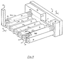
- Fig. 3 is a perspective view illustrating a segmented roller utilized in the apparatus of Figs. 1 and 2;
- Fig. 4 is a perspective view of the apparatus of Fig. 1 with a portion thereof broken away to further illustrate construction details thereof; and,
- Fig. 5 is a section view further illustrating the apparatus of Fig. 4 and taken along section line 5-5 thereof.
- Briefly, in accordance with my invention, I provide a dynamic flood conveyor. The flood conveyor includes a pair of upstanding spaced apart side walls; generally horizontally oriented adjacent parallel support rollers for supporting and transporting said piece of material, the support rollers including first and second end rollers and a third roller intermediate the end rollers and spanning the space between the side walls, having first and second ends each rotatably mounted in one of the walls, and having a cylindrical outer surface spanning the space between the side walls, the uppermost portion of the cylindrical surface of the rollers each generally lying in and defining a common generally horizontal imaginary plane means for rotating each of the support rollers in a common direction; a plurality of lower fluid containment rollers each sealingly interposed between, continuously contacting and rotating on top of and intermediate the cylindrical surfaces of an adjacent pair of support rollers, and rotating in a direction opposite the common direction of rotation of the support rollers; a pair of upper fluid containment rollers each spanning the space between said side walls, having a pair of ends each rotatably mounted in one of the side walls, and positioned above and generally parallel to one of the first and second end rollers and continuously contacting at least one of a first contact pair, the contact pair comprising the cylindrical outer surface of one of the end rollers, and the upper surface of a piece of material passing between the upper fluid containment roller and the one of the end support rollers; a reservoir of fluid in the flood conveyor, the fluid reservoir generally being above the support rollers and the lower fluid containment rollers, being between the upper fluid containment rollers, and extending above the imaginary plane; at least on disk spaced apart from the side walls, and positioned above the third roller and continuously contacting and rotating over a portion of one of a second contact pair, the second contact pair comprising the cylindrical outer surface of the third roller, and the upper surface of a piece of material passing between and simultaneously contacting the upper disk and the third support roller. The disk prevents a piece of material passing between the disk and third roller from upwardly rising away from contact with the third roller and, for a piece of material passing between the disk and third roller, exposing to fluid in the reservoir the upper surface of the portion of the piece of material contacting the third roller and not contacting the disk. The flood conveyor also includes means for injecting fluid into the reservoir. At least one of the upper fluid containment rollers includes a generally horizontally oriented shaft and is segmented into a plurality of cylindrical segments, each of the segments having an aperture formed therethrough which circumscribes the shaft and is shaped and dimensioned to permit the segment to be vertically displaced with respect to the shaft.
- Turning now to the drawings, which depict the presently preferred embodiments of the invention for the purpose of illustrating the practice thereof and not by way of limitation of the scope of the invention, and in which like reference characters refer to corresponding elements throughout the several views, Figs. 1 and 2 illustrate a dynamic flood conveyor constructed in accordance with the principles of the invention and including
upstanding side walls 11 and 12 and parallel support rollers 13 - 18 each having first 19 and second 60 ends rotatably mounted in one ofside walls 11 and 12.Rollers outer surface 13A-18A. Rollers 13-18 support and transport a strip of material 25 through the dynamic flood conveyor in the direction of arrow A. Rollers 13-18 each turn in the direction indicated by arrows B. Theends 19 of each adjacent pair of support rollers 13-18 are presently equally spaced apart. Eachend 19 is rotatably positioned in one of a series of parallel, vertical, spaced apartretainer slots 26 formed inwall 12. The width of aslot 26 is uniform along its length and is slightly greater than the outer diameter of a bushing 40 on anend 18. Similarly, eachend 60 is rotatably positioned in one of a series of parallel, vertical, spaced apartretainer slots 27 formed in wall 11. The width ofslot 27 is uniform along its length and is slightly greater than the outer diameter of abushing 40 on anend 60.End 60 of each roller 13-18 carries a chain sprocket 28 fixedly attached thereto. A movingchain 29 engages and rotates each sprocket 28 and roller 13-18. Wall 11 includesside dam member 30 extending therealong.End 60 of each support roller 13-18 rotatably extends through anaperture 31 formed throughside dam 30. Cylindrical low friction plastic washers 32 seal the space between each roller 13-18 andwalls 11 and 12. - Elongate cylindrical lower fluid containment rollers 20-24 are interposed between and continuously contact and rotate on top of and intermediate the outer
cylindrical surfaces 13A-18A of each adjacent pair of support rollers 13-18. For instance, lowerfluid containment roller 20 is interposed betweensurfaces 13A and 14A ofroller pair 13, 14. Fluid containment rollers 20-24 are rotated in the direction of arrows C by support rollers 13-18. Each fluid containment roller 20-24 is presently of a diameter slightly less than that which would cause the roller to protrude above a generally horizontal imaginary plane passing through substrate strip 25, and has a length less than the distance D betweenside wall 12 andside dam member 30. Each roller 20-24 substantially seals the cylindrical outer surfaces of an adjacent support roller 12-18 pair while generally not impeding the free rotation of the roller pair. Upperfluid containment rollers end rollers shafts 37 ofrollers side walls 11 and 12. Cylindrical low frictionplastic washers walls 11 and 12. One end ofshaft 37 ofroller 35A extends into avertical slot 26 receivingend 19 ofroller 13. The other end ofshaft 37 ofroller 35A extends into avertical slot 27 receivingend 20 ofroller 13. The diameter of each end of ashaft 37 is presently generally equivalent to the diameter ofends shaft 37 ofroller 35A rotatably passes through an aperture formed throughside dam member 30 in the same manner as one end ofshaft 37 onroller 36A does throughaperture 39 in Fig. 2. The portions of eachend shafts 37 in aslot bushing 40 secured thereto. One end ofshaft 37 ofroller 36A extends intovertical slot 26 which receives end 19 ofroller 18. The other end ofshaft 37 ofroller 36A also extends intovertical slot 27 which receives end 60 ofroller 18. End 38 ofroller 36A rotatably extends through anaperture 39 formed inside dam 30.Rollers 36A contact rollers rollers rollers rollers rollers - Spaced apart disks 41 are fixedly attached to shaft 42. The ends of shaft 42 rotatably extend into
vertical slots roller 16. The end of rod 42 extending into aslot 27 also rotatably passes through an aperture formed throughside dam member 30 in thesame manner aperture 39 is formed throughmember 30 for end ofroller 36A. Disks 41 on shaft 42 contact theouter surface 16A ofroller 16 or contact strip 25 traveling overroller 16. Motive power is transmitted fromroller 16 tofriction wheel 54 at the end of shaft 42 carrying disks 41 and causes disks 41 and shaft 42 to turn in the direction indicated by arrow E. Disks 41 prevent a strip of material 25 passing through the apparatus of Figs. 1 and 2 from floating upwardly away from the uppermost portions of support rollers 13-18. The uppermost portions of rollers 13-18 lie in and define a horizontally oriented imaginary plane. In Fig. 1, strip of material 25 lies in this imaginary plane. The imaginary plane is, in Fig. 1, perpendicular to the plane of the paper of the drawings. Since lower fluid containment rollers 20-24 rotate in a direction which would cause rollers 20-24 to oppose the movement of strip 25 in the direction of arrow A, the diameter of rollers 20-24 is preferably small enough so that rollers 20-24 are each positioned beneath the imaginary plane intersecting the uppermost portions of rollers 13-18. - Fluid in
reservoir 43 generally is above support rollers 13-18 and lower fluid containment rollers 20-24, is between upper fluid containment rollers 35 and 36, and extends above the imaginary plane extending through the uppermost portions of rollers 13-18. - During operation of the apparatus of Figs. 1 and 2, fluid from
reservoir 43 seeps between lower fluid containment rollers 2-24 and support rollers 13-18, and between upperfluid containment rollers rollers reservoir 43 through at least one conduit member 44 having at least one nozzle mouth 46. positioned beneath the surface ofreservoir 43. Fluid flows from nozzle mouth 46 in the directions of travel indicated by arrows F and G. The directions of flow F and G offluid 45 intoreservoir 43 are generally parallel to the imaginary plane intersecting the uppermost portions of rollers 13-18, are generally parallel to the planer surface of strip 25, and are generally parallel to the direction of travel A of strip 25 through the apparatus. Consequently, the introduction offluid 45 into thereservoir 43 in the direction of arrows F and G promotes the uniform laminar flow of fluid over the upper surface of strip 25. Nozzle mouth 46 is presently preferably positioned above the pass line, i.e., above the upper surface of strip 25. The uniform laminar flow of fluid over the upper surface of strip 25 minimizes the formation of eddy currents influid reservoir 43 and therefore facilitates the transport of very thin substrate strips 25, and tends to eliminate "dead" areas of chemical interaction between fluid inreservoir 43 and strip 25. The flow rate offluid 45 through conduit 44 intoreservoir 43 is adjusted to compensate for and generally equal fluid losses fromreservoir 43 during operation of the apparatus. - A nozzle mouth 46 can also, if desired, be positioned above the surface of
reservoir 43. Mouth 46 can, regardless of the position of mouth 46 above or beneath the surface ofreservoir 43, be shaped and dimensioned such that fluid flowing through mouth 46 travels radially outwardly away from nozzle 44 in any selected directions(s) of travel. Further, while the direction of travel of fluid emitted from mouth 46 and flowing away from nozzle 44 is presently preferably parallel to the imaginary plane lying in material 25 passing beneath nozzle 44, mouth 46 can also be shaped and dimensioned such that fluid emitted by mouth 46 flows upwardly away from and/or downwardly toward material 25. - The apparatus of the invention permits the use of solutions in
reservoir 43 which contain a high quantity of surfactants. Solutions with a high quantity of surfactants are generally not suitable for use in spray treatment apparatus. - Side walls 11 are connected to a
base 50 and endwalls 51 and 52. Any suitable source of motive power can be utilized to drivechain 29. - The ends of
shafts 37 ofrollers respective slots rollers -
Rollers segments 80. Eachsegment 80 has a shape and dimension equal to the other remainingsegments 80. Eachsegment 80 includes a pair of planar, spaced apart, parallel side faces 78 and 79.Faces Cylindrical aperture 81 extends through eachsegment 80 and interconnects faces 78 and 79. Eachsegment 80 touches at least one immediately adjoiningsegment 80. In particular, theface 78 of one segment slidably contacts theface 79 of an immediately adjoining segment. In Figs. 4 and 5 the segments are drawn in their normal adjoining relationship. In Fig. 3,segments 80 are drawn with a small space in between each adjoining pair ofsegments 80. These small spaces do not exist during use of the apparatus of the invention, and are incorporated in Fig. 3 to emphasize that eachsegment 80 preferably is not connected to adjoiningsegments 80. - In Figs. 1, 3 and 5,
segments shafts 37.Apertures 81 are spaced away fromshafts 37. Under actual operating conditions, the weight ofsegments 80, the weight ofshafts 37, the force W1 and W2 of the fluid in the reservoir bearing outwardly againstrollers segments 80 cause therollers roller apertures 81contact shaft 37. When a circuit board substrate orother workpiece 82 moves betweenrollers 36A and 18 (and betweenrollers 35A and 13), thesegments 80 contacting theworkpiece 82 are upwardly displaced in the direction indicated by arrows K in Figs. 3 and 5.Apertures 81, which have an inner diameter larger than the outer diameter ofshafts 37 and free floatingshaft 37, enable this upward displacement ofsegments 80 in Figs. 3 and 5. Thesegments 80 which do not contactworkpiece 82 remain in contact withroller 18. After workpiece 82 has moved completely throughrollers segments 80, thesegments 80 which contacted theworkpiece 82 return to the position indicated in Fig. 2, contactingroller 18. The faces 78 and 79 ofsegments 80 must slidably move over one another such that whenworkpiece 82 moves betweenrollers 36A and 18 (orroller 35A and 13), only thesegments 80 contactingworkpiece 82 are upwardly displaced in the direction of arrows K from contact withroller 18. For example, in Fig. 5 the upwardly displacedsegment 80 which is the furthest to the left of thesegments 80 contacting 82 slidably moved upwardly overface 79 of the adjoiningsegment 80 to its left and said adjoiningsegment 80 remained in contact with roller 13 (roller 13 is not visible in Fig. 5). - Figs. 4 and 5 illustrate the weir overflow system utilized in the invention to minimize the formation of foam in the closed circuit liquid recirculation system. The normal fluid level in the apparatus of the invention is indicated by dashed
lines 43 in Figs. 2, 4 and 5. As indicated by the different elevations of the dashedlines 43 in the drawings, the depth of liquid in the flood can vary as desired. The depth of liquid in the flood is preferably sufficient to minimize turbulence caused on the surface of theworkpiece 82 by liquid returned to the bath through mouth 46 and is sufficient to assist in generating onsegments 80 of forces indicated by arrows W1 and W2 in Fig. 4. Fluid being returned to the flood is indicated byarrows 45 in Figs. 1 and 5. Thefluid flow 45 into the flood is sufficient to compensate for fluid losses which occur through small apertures 100 and 101 (Fig. 5) between a workpiece 82 andadjacent segments 80 which are still in contact withroller 16. Thefluid flow 45 is also sufficient to maintain fluid flowing out of the flood overweir 86 intosump 90.Valve 85 controls the rate at which fluid fromsump 90 flows under gravity tosump 87.Pump 88 returns 45 fluid fromsump 87 to the floodintermediate rollers weir 86 flowed intosump 90 tends to remain on the surface of the fluid 83 insump 90 when fluid 83 flows downwardly intosump 87. Further, sincepump 88 draws liquid from beneath the surface of the liquid 84 insump 87, any foam insump 87 tends to remain on the surface offluid 84. Consequently, the weir fluid overflow system of the invention minimizes the amount of foam in liquid being returned 45 to the flood. Since the flow of fluid, indicated by arrow V in Fig. 4, is transverse the direction of the flow of fluid indicated by arrows F and G in Fig. 1, the surface fluid flow overweir 86 in the direction of arrow V tends to offset the flow of fluid in the direction of arrows F and G and stabilize the surface of the liquid in the flood. - The width, indicated in Fig. 5 by arrows N, of each
segment 80 is 203,3 cm (0.75 inch) or less, and for pieces of substrate greater than 0,3175 cm (one eighth of an inch) thick is preferably 0,635 cm (0.25 inch) or less. - As earlier noted,
shafts 37 are free floating and can be vertically displaced invertical slots roller shaft 37 also bears down againstapertures 81 ofsegments 80 and, along with the weight ofsegments 80, maintains segments againstrollers shaft 37 was not free floating, but was instead held in a fixed position, such fixed position could position theshaft 37 in the upper part ofapertures 81 of aroller segments 80 were resting on aroller segments 80 to be upwardly displaced until the lower parts of apertures contacted the bottom of ashaft 37. In this kind of "fixed shaft" 37 configuration, the weight of theshaft 37 would not be available to help forcesegments 80 against aroller segments 80 would have to be weighted or sized to insure that the liquid in the flood could not force its way betweensegments 80 and aroller segments 80 upwardly from contact with theroller larger diameter segments 80 would weigh more and facilitate the maintaining ofsegments 80 in contact with aroller 13 or 18 (or in contact with aworkpiece 82 passing betweensegments 80 and aroller 13 or 18). - Having described my invention in such terms as to enable those skilled in the art to understand and practise it, and having identified the presently preferred embodiments thereof, I Claim:
Claims (1)
- A dynamic flood conveyor for processing the upper surface of a circuit board substrate by moving the substrate through a body of fluid, said substrate having an upper surface, said conveyor including(a) a pair of upstanding spaced apart side walls (11, 12);(b) generally horizontally oriented adjacent parallel support rollers for supporting and transporting said circuit board substrate, said support rollers,(i) including at least first (18) and second (13) end rollers,(ii) each spanning the space between said side walls,(iii) each having first and second ends each rotatably mounted in one of said walls (11, 12), and(iv) each having a cylindrical outer surface (18A, 13A) spanning the space between said side walls,each of the uppermost portion of said cylindrical outer surfaces of said rollers each generally lying in and defining a common generally horizontal imaginary plane;(c) means for rotating each of said support rollers (18, 13) in a common direction;(d) upper fluid containment roller means (35A) extending above said horizontal plane and spanning the space between said side walls;(e) an upper fluid containment roller (36A) spaced apart from said upper fluid containment roller means (35A), spanning the space between said side walls, positioned above and generally parallel to said first end roller, and including(i) a horizontally oriented shaft (37), and(ii) a pair of ends each rotatably mounted in one of said side walls (11, 12);(f) a reservoir of fluid (43) in said flood conveyor, said fluid reservoir contacting said fluid containment roller (36A) and upper fluid containment roller means (35A) and generally extending(i) above said support rollers,(ii) between and contacting said fluid containment roller (36A) and said upper fluid containment roller means (35A), and(iii) above said imaginary plane; and(g) means for injecting fluid into said reservoir, said fluid containment roller (36A) and upper fluid containment roller means (35A) acting as dams to retain fluid in said reservoir (43);characterized in that said upper fluid containment roller (36A) includes a plurality of cylindrical segments (80) slidably contacting one another and rotatably mounted on said shaft (37), each of said segments having an aperture (81) formed therethrough which is shaped and dimensioned to permit said segments to be vertically displaced with respect to said shaft and said first end roller, said segments extending from one of said side walls to the other of said side walls and positioned generally parallel to said first end roller (18) and continuously contacting at least one of a second contact pair, said second contact pair comprising(i) said cylindrical outer surface (18A) of said first end roller (18), and(ii) the upper surface of said circuit board substrate (82) passing between said fluid containment roller (36A) and said first end roller (18A),selected ones of said segments (80) remaining in contact with said end roller (18) simultaneously with the remaining others of said segments (80) being upwardly displaced with respect to said selected ones of said segments on contacting the upper surface of said circuit board substrate (82) passing between said fluid containment roller (36A) and said first end roller (18) while moving toward said fluid containment means (35A), and said upward displacement of said remaining others of said segments (80) of said fluid containment roller with respect to said selected ones of said segments (80) of said fluid containment roller (36A) minimizing the fluid escaping from said reservoir over said first end roller (18) when said circuit board substrate (82) passes between said fluid containment roller (36A) and said first end roller (18) into said reservoir (43).
Applications Claiming Priority (2)
| Application Number | Priority Date | Filing Date | Title |
|---|---|---|---|
| US07/485,167 US5007445A (en) | 1990-02-26 | 1990-02-26 | Dynamic flood conveyor with weir |
| US485167 | 1990-02-26 |
Publications (3)
| Publication Number | Publication Date |
|---|---|
| EP0444359A2 EP0444359A2 (en) | 1991-09-04 |
| EP0444359A3 EP0444359A3 (en) | 1993-03-24 |
| EP0444359B1 true EP0444359B1 (en) | 1995-03-01 |
Family
ID=23927145
Family Applications (1)
| Application Number | Title | Priority Date | Filing Date |
|---|---|---|---|
| EP90314259A Expired - Lifetime EP0444359B1 (en) | 1990-02-26 | 1990-12-24 | Dynamic flood conveyor with weir |
Country Status (3)
| Country | Link |
|---|---|
| US (1) | US5007445A (en) |
| EP (1) | EP0444359B1 (en) |
| DE (1) | DE69017423T2 (en) |
Families Citing this family (16)
| Publication number | Priority date | Publication date | Assignee | Title |
|---|---|---|---|---|
| DE4121079A1 (en) * | 1991-06-26 | 1993-01-07 | Schmid Gmbh & Co Geb | DEVICE FOR TREATING PLATE-SHAPED OBJECTS |
| US5294259A (en) * | 1992-05-18 | 1994-03-15 | International Business Machines Corporation | Fluid treatment device |
| US5378307A (en) * | 1993-04-28 | 1995-01-03 | International Business Machines Corporation | Fluid treatment apparatus |
| US5592958A (en) * | 1995-02-01 | 1997-01-14 | Coates, Asi, Inc. | Flood conveyer |
| US5837067A (en) * | 1995-06-07 | 1998-11-17 | International Business Machines Corporation | Precision fluid head transport |
| US5795625A (en) * | 1996-07-16 | 1998-08-18 | Eastman Kodak Company | Coating solution distribution apparatus |
| DE05075545T1 (en) * | 1998-05-20 | 2006-08-31 | Process Automation International Ltd., Tai Po | Apparatus for electroplating |
| DE19934300C2 (en) * | 1999-07-21 | 2002-02-07 | Steag Micro Tech Gmbh | Device for treating substrates |
| AT408453B (en) * | 1999-09-03 | 2001-12-27 | Andritz Ag Maschf | METHOD FOR TREATMENT, IN PARTICULAR RINSING, OF A METAL STRIP |
| DE102008022282A1 (en) * | 2008-04-24 | 2009-10-29 | Gebr. Schmid Gmbh & Co. | Device and method for treating silicon wafers or flat objects |
| USD601597S1 (en) | 2008-09-03 | 2009-10-06 | P & B Construction, Inc. | Enclosed chamber, adjustable finish-applicator for flat and dimensional surfaces |
| BRPI1011369A2 (en) | 2009-05-13 | 2016-03-15 | Atotech Deutschland Gmbh | method, treatment plant and assembly for treating a flat material to be treated |
| CN103286032B (en) * | 2013-05-31 | 2016-05-04 | 京东方科技集团股份有限公司 | Coating apparatus and color membrane substrates manufacture craft |
| CN109436693B (en) * | 2018-10-10 | 2020-08-28 | 上海航天化工应用研究所 | Dust-proof conveying device under dangerous operation environment |
| CN110420795A (en) * | 2019-08-02 | 2019-11-08 | 马鞍山致青工业设计有限公司 | A kind of sheet fabrication coating roller of the uniform japanning of quick-dry type |
| CN112170118B (en) * | 2020-09-30 | 2021-10-01 | 杭州汇家厨卫用品有限公司 | An anti-static paint wiping equipment for anti-static plate processing |
Family Cites Families (5)
| Publication number | Priority date | Publication date | Assignee | Title |
|---|---|---|---|---|
| US1455A (en) * | 1839-12-31 | Lewis r | ||
| DE3001726C2 (en) * | 1980-01-18 | 1984-08-09 | Gebr. Schmid GmbH & Co, 7290 Freudenstadt | Device for treating a printed circuit board |
| JPS587830A (en) * | 1981-07-08 | 1983-01-17 | Hitachi Ltd | Method and apparatus for cleaning flaky articles |
| US4591169A (en) * | 1985-06-19 | 1986-05-27 | Rca Corporation | Seal arrangement for retaining a liquid level above a strip passing through a chamber |
| US4724856A (en) * | 1986-03-17 | 1988-02-16 | Pender Don P | Dynamic flood conveyor |
-
1990
- 1990-02-26 US US07/485,167 patent/US5007445A/en not_active Expired - Fee Related
- 1990-12-24 DE DE69017423T patent/DE69017423T2/en not_active Expired - Fee Related
- 1990-12-24 EP EP90314259A patent/EP0444359B1/en not_active Expired - Lifetime
Also Published As
| Publication number | Publication date |
|---|---|
| EP0444359A3 (en) | 1993-03-24 |
| US5007445A (en) | 1991-04-16 |
| DE69017423D1 (en) | 1995-04-06 |
| DE69017423T2 (en) | 1995-09-07 |
| EP0444359A2 (en) | 1991-09-04 |
Similar Documents
| Publication | Publication Date | Title |
|---|---|---|
| US5007445A (en) | Dynamic flood conveyor with weir | |
| US4724856A (en) | Dynamic flood conveyor | |
| KR101341146B1 (en) | Method, treatment station and assembly for treating a planar material to be treated | |
| US3752054A (en) | Automatic processor for emulsion coated metal templates | |
| US3403098A (en) | Oil skimmers | |
| US3023686A (en) | Automatic film processing apparatus | |
| US4023190A (en) | Film processor | |
| CN218757334U (en) | Sluice rubbish intercepting device for hydraulic engineering | |
| KR930703630A (en) | Photo processing equipment | |
| US3692465A (en) | Three roll processing apparatus,and method for utilization thereof | |
| EP0495288B1 (en) | Roller tank | |
| US5634481A (en) | Strip treatment installation | |
| JP3735746B2 (en) | Suspended scraping device | |
| CN1098375C (en) | Device for processing flat workpieces, in particular printed circuit boards | |
| US2919705A (en) | Apparatus for treating articles | |
| WO1998044389A1 (en) | An apparatus and a method for processing photographic material | |
| JP2607864Y2 (en) | Sludge and suspended matter scraping device | |
| US5426480A (en) | Photographic film processing apparatus | |
| CN222677271U (en) | Scum scraping mechanism of sedimentation tank | |
| JP2514249Y2 (en) | Transition roller cleaning device in automatic processor | |
| JPS5653792A (en) | Guide for aeration tank | |
| US20110097074A1 (en) | High speed motion picture film processor | |
| JP3241154B2 (en) | IC lead frame surface treatment equipment | |
| DE2225637C3 (en) | Device for the treatment of leaf material | |
| JPH0133646Y2 (en) |
Legal Events
| Date | Code | Title | Description |
|---|---|---|---|
| PUAI | Public reference made under article 153(3) epc to a published international application that has entered the european phase |
Free format text: ORIGINAL CODE: 0009012 |
|
| AK | Designated contracting states |
Kind code of ref document: A2 Designated state(s): DE FR GB IT |
|
| PUAL | Search report despatched |
Free format text: ORIGINAL CODE: 0009013 |
|
| AK | Designated contracting states |
Kind code of ref document: A3 Designated state(s): DE FR GB IT |
|
| 17P | Request for examination filed |
Effective date: 19930916 |
|
| 17Q | First examination report despatched |
Effective date: 19931029 |
|
| GRAA | (expected) grant |
Free format text: ORIGINAL CODE: 0009210 |
|
| AK | Designated contracting states |
Kind code of ref document: B1 Designated state(s): DE FR GB IT |
|
| REF | Corresponds to: |
Ref document number: 69017423 Country of ref document: DE Date of ref document: 19950406 |
|
| ITF | It: translation for a ep patent filed | ||
| ET | Fr: translation filed | ||
| PLBQ | Unpublished change to opponent data |
Free format text: ORIGINAL CODE: EPIDOS OPPO |
|
| PLBI | Opposition filed |
Free format text: ORIGINAL CODE: 0009260 |
|
| PLBF | Reply of patent proprietor to notice(s) of opposition |
Free format text: ORIGINAL CODE: EPIDOS OBSO |
|
| PLBF | Reply of patent proprietor to notice(s) of opposition |
Free format text: ORIGINAL CODE: EPIDOS OBSO |
|
| PLBF | Reply of patent proprietor to notice(s) of opposition |
Free format text: ORIGINAL CODE: EPIDOS OBSO |
|
| 26 | Opposition filed |
Opponent name: GEBR. SCHMID GMBH & CO. Effective date: 19951201 |
|
| PLBF | Reply of patent proprietor to notice(s) of opposition |
Free format text: ORIGINAL CODE: EPIDOS OBSO |
|
| PLBF | Reply of patent proprietor to notice(s) of opposition |
Free format text: ORIGINAL CODE: EPIDOS OBSO |
|
| PLBO | Opposition rejected |
Free format text: ORIGINAL CODE: EPIDOS REJO |
|
| PGFP | Annual fee paid to national office [announced via postgrant information from national office to epo] |
Ref country code: GB Payment date: 19981231 Year of fee payment: 9 Ref country code: FR Payment date: 19981231 Year of fee payment: 9 |
|
| PGFP | Annual fee paid to national office [announced via postgrant information from national office to epo] |
Ref country code: DE Payment date: 19990107 Year of fee payment: 9 |
|
| PLBN | Opposition rejected |
Free format text: ORIGINAL CODE: 0009273 |
|
| STAA | Information on the status of an ep patent application or granted ep patent |
Free format text: STATUS: OPPOSITION REJECTED |
|
| 27O | Opposition rejected |
Effective date: 19981102 |
|
| PG25 | Lapsed in a contracting state [announced via postgrant information from national office to epo] |
Ref country code: GB Free format text: LAPSE BECAUSE OF NON-PAYMENT OF DUE FEES Effective date: 19991224 |
|
| GBPC | Gb: european patent ceased through non-payment of renewal fee |
Effective date: 19991224 |
|
| PG25 | Lapsed in a contracting state [announced via postgrant information from national office to epo] |
Ref country code: FR Free format text: LAPSE BECAUSE OF NON-PAYMENT OF DUE FEES Effective date: 20000831 |
|
| PG25 | Lapsed in a contracting state [announced via postgrant information from national office to epo] |
Ref country code: DE Free format text: LAPSE BECAUSE OF NON-PAYMENT OF DUE FEES Effective date: 20001003 |
|
| REG | Reference to a national code |
Ref country code: FR Ref legal event code: ST |
|
| PG25 | Lapsed in a contracting state [announced via postgrant information from national office to epo] |
Ref country code: IT Free format text: LAPSE BECAUSE OF NON-PAYMENT OF DUE FEES;WARNING: LAPSES OF ITALIAN PATENTS WITH EFFECTIVE DATE BEFORE 2007 MAY HAVE OCCURRED AT ANY TIME BEFORE 2007. THE CORRECT EFFECTIVE DATE MAY BE DIFFERENT FROM THE ONE RECORDED. Effective date: 20051224 |