EP0444002B1 - Method for dewatering particle collections - Google Patents
Method for dewatering particle collections Download PDFInfo
- Publication number
- EP0444002B1 EP0444002B1 EP91850042A EP91850042A EP0444002B1 EP 0444002 B1 EP0444002 B1 EP 0444002B1 EP 91850042 A EP91850042 A EP 91850042A EP 91850042 A EP91850042 A EP 91850042A EP 0444002 B1 EP0444002 B1 EP 0444002B1
- Authority
- EP
- European Patent Office
- Prior art keywords
- press
- dewatering
- filter
- pressure
- mass
- Prior art date
- Legal status (The legal status is an assumption and is not a legal conclusion. Google has not performed a legal analysis and makes no representation as to the accuracy of the status listed.)
- Expired - Lifetime
Links
- 238000000034 method Methods 0.000 title claims abstract description 45
- 239000002245 particle Substances 0.000 title claims abstract description 12
- 125000004122 cyclic group Chemical group 0.000 claims abstract description 3
- 239000000463 material Substances 0.000 description 8
- 238000007664 blowing Methods 0.000 description 6
- 239000012065 filter cake Substances 0.000 description 5
- 238000003825 pressing Methods 0.000 description 4
- 239000000725 suspension Substances 0.000 description 4
- XLYOFNOQVPJJNP-UHFFFAOYSA-N water Substances O XLYOFNOQVPJJNP-UHFFFAOYSA-N 0.000 description 4
- 238000005303 weighing Methods 0.000 description 4
- 239000004744 fabric Substances 0.000 description 3
- 239000007788 liquid Substances 0.000 description 3
- 239000000047 product Substances 0.000 description 3
- 238000004140 cleaning Methods 0.000 description 2
- 238000005265 energy consumption Methods 0.000 description 2
- 229910052500 inorganic mineral Inorganic materials 0.000 description 2
- 238000005259 measurement Methods 0.000 description 2
- 239000011707 mineral Substances 0.000 description 2
- 230000035515 penetration Effects 0.000 description 2
- 238000005406 washing Methods 0.000 description 2
- 230000015556 catabolic process Effects 0.000 description 1
- 230000003247 decreasing effect Effects 0.000 description 1
- 238000001704 evaporation Methods 0.000 description 1
- 230000008020 evaporation Effects 0.000 description 1
- 239000000835 fiber Substances 0.000 description 1
- 238000001914 filtration Methods 0.000 description 1
- 230000000977 initiatory effect Effects 0.000 description 1
- 230000000737 periodic effect Effects 0.000 description 1
Images
Classifications
-
- B—PERFORMING OPERATIONS; TRANSPORTING
- B01—PHYSICAL OR CHEMICAL PROCESSES OR APPARATUS IN GENERAL
- B01D—SEPARATION
- B01D37/00—Processes of filtration
- B01D37/04—Controlling the filtration
-
- B—PERFORMING OPERATIONS; TRANSPORTING
- B01—PHYSICAL OR CHEMICAL PROCESSES OR APPARATUS IN GENERAL
- B01D—SEPARATION
- B01D25/00—Filters formed by clamping together several filtering elements or parts of such elements
- B01D25/12—Filter presses, i.e. of the plate or plate and frame type
-
- B—PERFORMING OPERATIONS; TRANSPORTING
- B30—PRESSES
- B30B—PRESSES IN GENERAL
- B30B9/00—Presses specially adapted for particular purposes
- B30B9/02—Presses specially adapted for particular purposes for squeezing-out liquid from liquid-containing material, e.g. juice from fruits, oil from oil-containing material
- B30B9/04—Presses specially adapted for particular purposes for squeezing-out liquid from liquid-containing material, e.g. juice from fruits, oil from oil-containing material using press rams
- B30B9/047—Control arrangements
Definitions
- the present invention relates to a method for dewatering particle collections in a cyclic sequence with the aid of a filter press, said sequence comprising the stages of filling, dewatering and emptying the press.
- Water-containing particle collections such as mineral suspensions and fibre suspensions, are often dewatered with the aid of a filter press, as indicated in the preamble.
- This second stage may consist of several part stages, normally mechanical pressing and air blowing.
- the third stage is then carried out, the emptying stage, which may also comprise several part stages.
- the dried material is then transported to a downstream station, normally with the aid of a conveyor belt.
- One method of endeavouring to optimize such methods is to improve the actual dewatering stage itself.
- One such method is described in our earlier patent specification SE-A-8802110-0 (and corresponding European EP-A-346312), in which the blowing stage of the dewatering process is effected in conjunction with following-up the pressure of the blowing air, so as to enable dewatering to be effected in one single part stage - penetration - instead of the three stages - penetration, draining and evaporation respectively-which would otherwise be used.
- Another method of endeavouring to optimize the dewatering methods is one of providing more sophisticated apparatus, therewith enabling dewatering to be effected with the least possible disturbance.
- a modern, advanced filter press which, among other things, provides an improved emptying operation, is described in our earlier patent specification SE-B-453 726 (and corresponding WO-A-88/00495).
- the present invention provides a method which will enable the entire dewatering process to be followed-up and controlled in a simple and effective manner so as to enable all process stages to be optimized, which means, among other things, that all stages can be initiated and terminated during the process at the most suitable occasion from the process aspect. Furthermore, each tendency to disturbance is indicated, for instance, disturbances caused by material supply, blockaging of the filter or incomplete emptying thereof.
- the various stages are followed-up within each cycle and between consecutive cycles, by continuously measuring a magnitude which varies with thie mass of the press and the press contents.
- masses of the press shall be understood throughout as including the mass of at least that part or parts of the press utilized for the actual dewatering process. Naturally, the mass can also concern the whole of the press, including the press stand, and components and devices of a more secondary nature to the inventive method.
- the expression “followed-up and determined” include the continuous registration of relevant data for producing relevant curves and optionally also direct entering of such measuring values into a data processor.
- reference to controlling the method implies, for instance, initiation and termination of part method steps at predetermined measurement values or when the operational curves produced have given slopes or show a breakdown tendency, as will be explained in more detail below with reference to examples of operational curves.
- the magnitude selected for following-up changes in the mass during the dewatering sequence may take many different forms and may, for instance, comprise the weight of the press, including its content, in those instances when the press is completely or partially supported by a weighing device, or the stretch which the press exerts on a stay or brace or the like, which lifts the press completely or partially. It is preferred, however, to utilize the pressure exerted by the mass of the press and its content onto the surface supporting the press.
- the pressure measured may be the total pressure acting on the press supporting surface, although it is more suitable to measure a pressure which is a function of the total pressure.
- the pressure is preferably measured and followed-up by sensors placed between the press support surface and the press itself.
- the pressure exerted by the mass of the press and its contents is measured solely on one side of a symmetry line drawn through the longitudinal axis of the press.
- the press may be freely mounted or resiliently mounted on the other side of the symmetry line. In this case, the pressure between the press supporting surface and one or more legs or press supports is measured.
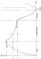
- the vertical axis of the illustrated curve represents a magnitude f(m) which is a function of the mass m of a filter press and its content, whereas the horizontal axis represents time, the curves also illustrating the propagation of the various part steps during a process cycle.
- the filling stage is introduced with the press emptied of material, wherein the magnitude f(m) can be set to zero.
- This value ⁇ is determined suitably empirically, i.e. on the basis of experience, for each type of filter and particle collection concerned, for instance with respect to filling volume, productivity achieved or the properties of the dewatered material.
- f(m) falls along a curve having a progressively decreasing inclination gradient, at least towards the end.
- a predetermined inclination gradient here expressed as an angle ⁇
- ⁇ a predetermined inclination gradient
- the magnitude f(m) will rapidly decrease during the emptying phase, often sporadically as indicated in the drawing, due to the fact that a larger part of the filter cake falls from the filter due to vibration of the cloth, whereas the curve becomes somewhat flatter towards the end of the emptying phase.
- emptying is terminated.
- rinsing is commenced with the intention of rinsing away any remaining dewatered filter cakes from the filter cloths, and also with the intention of cleaning and washing the cloths as thoroughly as possible, so that the cloths can be reused as effectively as possible, for dewatering in the following cycle.
- the mass will at first increase slightly, as evident from the drawing, due to the mass of wash liquid in the supply pipes and conduits in the press, whereas the mass will again fall when the supply of wash liquid is interrupted.
- the curve has reached the value "zero" and the press is thus empty and clean, a new dewatering cycle is commenced with the filling phase, as indicated in the drawing.
Landscapes
- Chemical & Material Sciences (AREA)
- Chemical Kinetics & Catalysis (AREA)
- Mechanical Engineering (AREA)
- Engineering & Computer Science (AREA)
- Solid-Sorbent Or Filter-Aiding Compositions (AREA)
- Filtration Of Liquid (AREA)
- Treatment Of Sludge (AREA)
- Seasonings (AREA)
- Sampling And Sample Adjustment (AREA)
- Water Treatment By Sorption (AREA)
- Extraction Or Liquid Replacement (AREA)
- Compounds Of Alkaline-Earth Elements, Aluminum Or Rare-Earth Metals (AREA)
- Silicon Compounds (AREA)
- Drying Of Solid Materials (AREA)
- Polysaccharides And Polysaccharide Derivatives (AREA)
Abstract
Description
- The present invention relates to a method for dewatering particle collections in a cyclic sequence with the aid of a filter press, said sequence comprising the stages of filling, dewatering and emptying the press.
- Water-containing particle collections, such as mineral suspensions and fibre suspensions, are often dewatered with the aid of a filter press, as indicated in the preamble.
- Problems are encountered when dewatering particle collections in a filter press, partly because of the difficulties of determining and following-up the amount of product to be dewatered that is charged to the press and partly with respect to optimizing the method and the various stages thereof. This is mainly because filter presses operate periodically or cyclically, as also indicated in the preamble. Thus, such methods usually comprise three stages. During the first stage, the filter is filled at the same time as filtering is effected on the filter cloth while forming a moist filter cake of particles on the cloth in the press. Subsequent to filling the filter in this way, the supply of particle collection to be dewatered is interrupted. During the second stage, the filter cake formed during the first stage is dewatered still further, to the desired water content. This second stage may consist of several part stages, normally mechanical pressing and air blowing. The third stage is then carried out, the emptying stage, which may also comprise several part stages. The dried material is then transported to a downstream station, normally with the aid of a conveyor belt. In addition to the aforesaid three main method stages, there is normally a last stage, the rinsing stage, in which the filter cloths are rinsed or washed with liquid in order to rinse off any filter cake residues that are present and also for washing and cleaning purposes.
- One common method of measuring the quantity of material dewatered involves the use of a belt scales, although such use is not totally idealistic, due to the periodic working cycles of the press filter. Consequently, it has been proposed in US-A-4 749 054 that the weight of each charge of dewatered material is determined by weighing the filter with dewatered product and, subsequent to emptying the filter, weighing the empty filter and calculating the difference between the two weighings. Although this known method may possibly solve one of the two problems associated with dewatering in press filters, namely the problem of determining the quantity of product dewatered in each cycle, the problem associated with optimizing the method in its entirety remains in principle, even though a certain degree of discontinuous follow-up with feed-back is made possible.
- In general, present day dewatering methods are controlled either by time-controlling the process stages or by quite simply controlling the various stages manually. The disadvantages with this are obvious, namely that all possible process disturbances will affect the dewatering process negatively, and energy consumption becomes unnecessarily high, because the process has not been optimized.
- Because of increasing energy costs and the progressively increasing industrial requirements on the dewatering of particle suspensions, demands have been made on further development of the dewatering methods so that they do not prohibit the handling of these materials from an energy aspect. At present it is considered that the energy costs are a very important factor in the total dewatering costs. Thus, there is an express desire for particle collection dewatering methods which will fulfil the requirements of low energy consumption and/or higher productivity.
- One method of endeavouring to optimize such methods is to improve the actual dewatering stage itself. One such method is described in our earlier patent specification SE-A-8802110-0 (and corresponding European EP-A-346312), in which the blowing stage of the dewatering process is effected in conjunction with following-up the pressure of the blowing air, so as to enable dewatering to be effected in one single part stage - penetration - instead of the three stages - penetration, draining and evaporation respectively-which would otherwise be used. Another method of endeavouring to optimize the dewatering methods is one of providing more sophisticated apparatus, therewith enabling dewatering to be effected with the least possible disturbance. A modern, advanced filter press which, among other things, provides an improved emptying operation, is described in our earlier patent specification SE-B-453 726 (and corresponding WO-A-88/00495).
- The present invention provides a method which will enable the entire dewatering process to be followed-up and controlled in a simple and effective manner so as to enable all process stages to be optimized, which means, among other things, that all stages can be initiated and terminated during the process at the most suitable occasion from the process aspect. Furthermore, each tendency to disturbance is indicated, for instance, disturbances caused by material supply, blockaging of the filter or incomplete emptying thereof.
- The invention is characterized by the steps set forth in the following claims.
- Thus, when practising the present invention the various stages are followed-up within each cycle and between consecutive cycles, by continuously measuring a magnitude which varies with thie mass of the press and the press contents. By "mass of the press" shall be understood throughout as including the mass of at least that part or parts of the press utilized for the actual dewatering process. Naturally, the mass can also concern the whole of the press, including the press stand, and components and devices of a more secondary nature to the inventive method. In this regard, the expression "followed-up and determined" include the continuous registration of relevant data for producing relevant curves and optionally also direct entering of such measuring values into a data processor. Furthermore, reference to controlling the method implies, for instance, initiation and termination of part method steps at predetermined measurement values or when the operational curves produced have given slopes or show a breakdown tendency, as will be explained in more detail below with reference to examples of operational curves.
- The magnitude selected for following-up changes in the mass during the dewatering sequence may take many different forms and may, for instance, comprise the weight of the press, including its content, in those instances when the press is completely or partially supported by a weighing device, or the stretch which the press exerts on a stay or brace or the like, which lifts the press completely or partially. It is preferred, however, to utilize the pressure exerted by the mass of the press and its content onto the surface supporting the press. The pressure measured may be the total pressure acting on the press supporting surface, although it is more suitable to measure a pressure which is a function of the total pressure. The pressure is preferably measured and followed-up by sensors placed between the press support surface and the press itself. According to one preferred method, the pressure exerted by the mass of the press and its contents is measured solely on one side of a symmetry line drawn through the longitudinal axis of the press. The press may be freely mounted or resiliently mounted on the other side of the symmetry line. In this case, the pressure between the press supporting surface and one or more legs or press supports is measured.
- The invention will now be described in more detail with reference to the accompanying drawing, the single figure of which illustrates an example of curves illustrating the progress of the dewatering process achieved in accordance with the invention.
- The vertical axis of the illustrated curve represents a magnitude f(m) which is a function of the mass m of a filter press and its content, whereas the horizontal axis represents time, the curves also illustrating the propagation of the various part steps during a process cycle.
- The filling stage is introduced with the press emptied of material, wherein the magnitude f(m) can be set to zero. As the filter is filled with water-containing particle collection, for instance mineral suspension, the total mass will increase and the magnitude f(m) will also increase along a curve having a successively lowering growth gradient which at

- Thus, filling is terminated at

- During the pressing and blowing process, f(m) falls along a curve having a progressively decreasing inclination gradient, at least towards the end. When a predetermined inclination gradient, here expressed as an angle β, is measured at


- It will be evident from the aforegoing that the process can be controlled readily on the basis of process curves similar to the curve illustrated in the drawing, and that all process steps can therewith be controlled by automatic devices with the aid of a data processor to which all measurement data is supplied continuously. It also lies within the scope of the present invention to utilize the measured magnitude in other ways for following-up and controlling the dewatering method.
Claims (6)
- A method for dewatering particle collections with the aid of a filter press in a cyclic sequence comprising filling, dewatering and emptying stages, characterized by following-up and determining the various stages within each cycle and between consecutive cycles by continuously measuring a magnitude which varies with the mass of the press and its contents.
- A method according to Claim 1, characterized in that said magnitude is the pressure exerted by the mass of the press and its contents on the surface supporting said press.
- A method according to Claim 2, characterized in that said pressure is a function of the total pressure.
- A method according to any one of Claims 2-3, characterized by following-up the pressure with the aid of sensors placed between the press supporting surface and the filter press.
- A method according to Claim 4, characterized by measuring the pressure on solely one side of the symmetry line that passes through the longitudinal axis of the press.
- A method according to Claim 5, characterized by measuring the pressure between the press supporting surface and one or more legs or supports of the press.
Applications Claiming Priority (2)
| Application Number | Priority Date | Filing Date | Title |
|---|---|---|---|
| SE9000623A SE465656B (en) | 1990-02-22 | 1990-02-22 | PROCEDURE FOR DRAINAGE OF PARTICLE COLLECTIONS |
| SE9000623 | 1990-02-22 |
Publications (2)
| Publication Number | Publication Date |
|---|---|
| EP0444002A1 EP0444002A1 (en) | 1991-08-28 |
| EP0444002B1 true EP0444002B1 (en) | 1994-12-07 |
Family
ID=20378637
Family Applications (1)
| Application Number | Title | Priority Date | Filing Date |
|---|---|---|---|
| EP91850042A Expired - Lifetime EP0444002B1 (en) | 1990-02-22 | 1991-02-20 | Method for dewatering particle collections |
Country Status (20)
| Country | Link |
|---|---|
| US (1) | US5167832A (en) |
| EP (1) | EP0444002B1 (en) |
| JP (1) | JP2989020B2 (en) |
| CN (1) | CN1026757C (en) |
| AT (1) | ATE114991T1 (en) |
| AU (1) | AU625851B2 (en) |
| BR (1) | BR9100632A (en) |
| CA (1) | CA2034289C (en) |
| DE (1) | DE69105547T2 (en) |
| DK (1) | DK0444002T3 (en) |
| ES (1) | ES2068561T3 (en) |
| FI (1) | FI92287B (en) |
| MX (1) | MX26802A (en) |
| NO (1) | NO176649C (en) |
| PL (1) | PL289153A1 (en) |
| PT (1) | PT96842B (en) |
| RU (1) | RU1829951C (en) |
| SE (1) | SE465656B (en) |
| ZA (1) | ZA911060B (en) |
| ZM (1) | ZM491A1 (en) |
Families Citing this family (5)
| Publication number | Priority date | Publication date | Assignee | Title |
|---|---|---|---|---|
| US5275740A (en) * | 1992-06-08 | 1994-01-04 | Jwi, Inc. | Filter press with adaptive automated control arrangement |
| CH689140A5 (en) * | 1994-02-18 | 1998-10-30 | Bucher Guyer Ag Masch | A method for controlling or regulating the pressing pressure of a press for solid-Fluessigtrennung. |
| US7153651B1 (en) * | 1996-10-31 | 2006-12-26 | Inverness Medical - Biostar, Inc. | Flow-through optical assay devices providing laminar flow of fluid samples, and methods of construction thereof |
| CN110947237B (en) * | 2019-11-29 | 2021-08-06 | 北京矿冶科技集团有限公司 | Collaborative optimization control method based on production balance of thickener-filter press |
| CN110975361B (en) * | 2020-03-05 | 2020-06-05 | 天津美腾科技股份有限公司 | Method and device for continuously discharging materials by multiple filter presses |
Family Cites Families (6)
| Publication number | Priority date | Publication date | Assignee | Title |
|---|---|---|---|---|
| US4439325A (en) * | 1982-08-06 | 1984-03-27 | Cpc Engineering Corporation | Pressurized filtration system |
| FI76639C (en) * | 1985-02-22 | 1988-11-10 | Outokumpu Oy | FOERFARANDE FOER MAENGDMAETNING AV TORKAD PRODUKT. |
| US4639312A (en) * | 1985-10-03 | 1987-01-27 | Texaco Inc. | Filter press flow control system for dewatering sludge |
| SE453726B (en) * | 1986-07-10 | 1988-02-29 | Sala International Ab | PROCESS FILTER PROCEDURE AND DEVICE |
| DE3832726C2 (en) * | 1988-01-25 | 1997-04-30 | Sartorius Gmbh | Drying balance with digital evaluation unit for determining the end point of drying |
| SE464171B (en) * | 1988-06-07 | 1991-03-18 | Sala International Ab | PROCEDURE FOR GAS PRESSURE DRAINAGE OF WATER-CONTAINING PARTICLE COLLECTION |
-
1990
- 1990-02-22 SE SE9000623A patent/SE465656B/en unknown
-
1991
- 1991-01-10 AU AU69255/91A patent/AU625851B2/en not_active Expired
- 1991-01-16 CA CA002034289A patent/CA2034289C/en not_active Expired - Lifetime
- 1991-01-17 US US07/642,420 patent/US5167832A/en not_active Expired - Lifetime
- 1991-02-04 FI FI910536A patent/FI92287B/en not_active Application Discontinuation
- 1991-02-04 ZM ZM4/91A patent/ZM491A1/en unknown
- 1991-02-08 BR BR919100632A patent/BR9100632A/en not_active IP Right Cessation
- 1991-02-13 ZA ZA911060A patent/ZA911060B/en unknown
- 1991-02-20 ES ES91850042T patent/ES2068561T3/en not_active Expired - Lifetime
- 1991-02-20 DE DE69105547T patent/DE69105547T2/en not_active Expired - Lifetime
- 1991-02-20 AT AT91850042T patent/ATE114991T1/en not_active IP Right Cessation
- 1991-02-20 DK DK91850042.2T patent/DK0444002T3/en active
- 1991-02-20 JP JP3026187A patent/JP2989020B2/en not_active Expired - Fee Related
- 1991-02-20 EP EP91850042A patent/EP0444002B1/en not_active Expired - Lifetime
- 1991-02-21 NO NO910697A patent/NO176649C/en not_active IP Right Cessation
- 1991-02-21 MX MX26802A patent/MX26802A/en unknown
- 1991-02-21 PL PL28915391A patent/PL289153A1/en unknown
- 1991-02-21 RU SU914894839A patent/RU1829951C/en active
- 1991-02-21 PT PT96842A patent/PT96842B/en not_active IP Right Cessation
- 1991-02-21 CN CN91101160A patent/CN1026757C/en not_active Expired - Lifetime
Also Published As
| Publication number | Publication date |
|---|---|
| AU6925591A (en) | 1991-08-29 |
| MX26802A (en) | 1994-05-31 |
| FI910536A0 (en) | 1991-02-04 |
| ZM491A1 (en) | 1991-09-27 |
| US5167832A (en) | 1992-12-01 |
| BR9100632A (en) | 1991-10-29 |
| DE69105547T2 (en) | 1995-04-13 |
| JPH04219106A (en) | 1992-08-10 |
| FI910536L (en) | 1991-08-23 |
| CN1054198A (en) | 1991-09-04 |
| CN1026757C (en) | 1994-11-30 |
| JP2989020B2 (en) | 1999-12-13 |
| SE9000623D0 (en) | 1990-02-22 |
| DK0444002T3 (en) | 1995-05-08 |
| PT96842A (en) | 1992-12-31 |
| EP0444002A1 (en) | 1991-08-28 |
| PT96842B (en) | 1998-08-31 |
| NO910697D0 (en) | 1991-02-21 |
| NO910697L (en) | 1991-08-23 |
| SE465656B (en) | 1991-10-14 |
| NO176649B (en) | 1995-01-30 |
| NO176649C (en) | 1995-05-10 |
| FI92287B (en) | 1994-07-15 |
| ATE114991T1 (en) | 1994-12-15 |
| ES2068561T3 (en) | 1995-04-16 |
| CA2034289C (en) | 1996-09-03 |
| DE69105547D1 (en) | 1995-01-19 |
| CA2034289A1 (en) | 1991-08-23 |
| PL289153A1 (en) | 1992-02-24 |
| SE9000623L (en) | 1991-08-23 |
| ZA911060B (en) | 1991-11-27 |
| AU625851B2 (en) | 1992-07-16 |
| RU1829951C (en) | 1993-07-23 |
Similar Documents
| Publication | Publication Date | Title |
|---|---|---|
| US3459122A (en) | Apparatus for the continuous extraction of moisture from suspended matter | |
| US3951809A (en) | Filter press | |
| US5167832A (en) | Method for dewatering particle collections controlled by monitoring changing mass | |
| CN114405156B (en) | Control method and control system of coal slime water pressure filter | |
| US4687986A (en) | Method and apparatus for measuring the streaming potential of a particle suspension | |
| EP0214259B1 (en) | Method for measuring the quantity of a dried product | |
| NL8403349A (en) | METHOD AND APPARATUS FOR MAKING SQUEEGEE BLEND FOR CHEESE PREPARATION. | |
| JPS6338181B2 (en) | ||
| CN217867026U (en) | Belt weigher discharging automatic vibration and feed opening emergency closing device | |
| CN206627195U (en) | Without roller-type low discharge high accuracy burden balance | |
| US1696639A (en) | Deinking process and means for performing same | |
| EP0318672B1 (en) | Device for checking the level and the movement of a mass in a vibrating machine | |
| CA1068579A (en) | Apparatus for separating tobacco from cigarettes | |
| WO1992012783A1 (en) | Method for filtering slurry or similar material in a continuous pressurized filter and filter suitable for the implementation of the method | |
| CN110967278A (en) | Compactness detection system for engineering detection and detection method thereof | |
| CN219908378U (en) | Belt type pulp washer | |
| CN104438115A (en) | Bobbin screening device | |
| CN210031291U (en) | Natural fiber plant raw material pulping, impregnating and material preparing system | |
| SU1756423A1 (en) | Apparatus for liquid processing woven material | |
| EP0803346A2 (en) | Double-belt press with high dewatering capacity | |
| JPS63137712A (en) | Dehydrating mechanism for fixing quantity of discharged cake | |
| CN120286467A (en) | A crushing device for classifying textiles by size | |
| RU2067636C1 (en) | Method for automatic control of continuous digestion of sulfate cellulose | |
| EP0788825A1 (en) | Filtering device for turbid water purification | |
| JPS60251842A (en) | Method and apparatus for determining steaming time in tea processing |
Legal Events
| Date | Code | Title | Description |
|---|---|---|---|
| PUAI | Public reference made under article 153(3) epc to a published international application that has entered the european phase |
Free format text: ORIGINAL CODE: 0009012 |
|
| AK | Designated contracting states |
Kind code of ref document: A1 Designated state(s): AT DE DK ES FR GB GR IT SE |
|
| 17P | Request for examination filed |
Effective date: 19920217 |
|
| 17Q | First examination report despatched |
Effective date: 19940329 |
|
| GRAA | (expected) grant |
Free format text: ORIGINAL CODE: 0009210 |
|
| AK | Designated contracting states |
Kind code of ref document: B1 Designated state(s): AT DE DK ES FR GB GR IT SE |
|
| REF | Corresponds to: |
Ref document number: 114991 Country of ref document: AT Date of ref document: 19941215 Kind code of ref document: T |
|
| REF | Corresponds to: |
Ref document number: 69105547 Country of ref document: DE Date of ref document: 19950119 |
|
| ET | Fr: translation filed | ||
| ITF | It: translation for a ep patent filed | ||
| PG25 | Lapsed in a contracting state [announced via postgrant information from national office to epo] |
Ref country code: SE Effective date: 19950307 |
|
| REG | Reference to a national code |
Ref country code: GR Ref legal event code: FG4A Free format text: 3014856 |
|
| REG | Reference to a national code |
Ref country code: ES Ref legal event code: FG2A Ref document number: 2068561 Country of ref document: ES Kind code of ref document: T3 |
|
| REG | Reference to a national code |
Ref country code: DK Ref legal event code: T3 |
|
| PLBE | No opposition filed within time limit |
Free format text: ORIGINAL CODE: 0009261 |
|
| STAA | Information on the status of an ep patent application or granted ep patent |
Free format text: STATUS: NO OPPOSITION FILED WITHIN TIME LIMIT |
|
| 26N | No opposition filed | ||
| REG | Reference to a national code |
Ref country code: GB Ref legal event code: IF02 |
|
| PGFP | Annual fee paid to national office [announced via postgrant information from national office to epo] |
Ref country code: ES Payment date: 20100312 Year of fee payment: 20 Ref country code: DK Payment date: 20100211 Year of fee payment: 20 |
|
| PGFP | Annual fee paid to national office [announced via postgrant information from national office to epo] |
Ref country code: FR Payment date: 20100223 Year of fee payment: 20 Ref country code: IT Payment date: 20100217 Year of fee payment: 20 |
|
| PGFP | Annual fee paid to national office [announced via postgrant information from national office to epo] |
Ref country code: GB Payment date: 20100202 Year of fee payment: 20 Ref country code: DE Payment date: 20100303 Year of fee payment: 20 Ref country code: AT Payment date: 20100212 Year of fee payment: 20 |
|
| PGFP | Annual fee paid to national office [announced via postgrant information from national office to epo] |
Ref country code: GR Payment date: 20100115 Year of fee payment: 20 |
|
| REG | Reference to a national code |
Ref country code: DE Ref legal event code: R071 Ref document number: 69105547 Country of ref document: DE |
|
| REG | Reference to a national code |
Ref country code: ES Ref legal event code: FD2A Effective date: 20110222 |
|
| REG | Reference to a national code |
Ref country code: DK Ref legal event code: EUP |
|
| REG | Reference to a national code |
Ref country code: GB Ref legal event code: PE20 Expiry date: 20110219 |
|
| PG25 | Lapsed in a contracting state [announced via postgrant information from national office to epo] |
Ref country code: GB Free format text: LAPSE BECAUSE OF EXPIRATION OF PROTECTION Effective date: 20110219 Ref country code: ES Free format text: LAPSE BECAUSE OF EXPIRATION OF PROTECTION Effective date: 20110221 |
|
| PG25 | Lapsed in a contracting state [announced via postgrant information from national office to epo] |
Ref country code: DE Free format text: LAPSE BECAUSE OF EXPIRATION OF PROTECTION Effective date: 20110220 |