EP0443804B1 - Facsimile apparatus - Google Patents
Facsimile apparatus Download PDFInfo
- Publication number
- EP0443804B1 EP0443804B1 EP91301289A EP91301289A EP0443804B1 EP 0443804 B1 EP0443804 B1 EP 0443804B1 EP 91301289 A EP91301289 A EP 91301289A EP 91301289 A EP91301289 A EP 91301289A EP 0443804 B1 EP0443804 B1 EP 0443804B1
- Authority
- EP
- European Patent Office
- Prior art keywords
- key
- function
- functions
- registration
- keys
- Prior art date
- Legal status (The legal status is an assumption and is not a legal conclusion. Google has not performed a legal analysis and makes no representation as to the accuracy of the status listed.)
- Expired - Lifetime
Links
Images


Classifications
-
- H—ELECTRICITY
- H04—ELECTRIC COMMUNICATION TECHNIQUE
- H04N—PICTORIAL COMMUNICATION, e.g. TELEVISION
- H04N1/00—Scanning, transmission or reproduction of documents or the like, e.g. facsimile transmission; Details thereof
- H04N1/0035—User-machine interface; Control console
- H04N1/00352—Input means
- H04N1/00384—Key input means, e.g. buttons or keypads
-
- H—ELECTRICITY
- H04—ELECTRIC COMMUNICATION TECHNIQUE
- H04N—PICTORIAL COMMUNICATION, e.g. TELEVISION
- H04N1/00—Scanning, transmission or reproduction of documents or the like, e.g. facsimile transmission; Details thereof
- H04N1/0035—User-machine interface; Control console
- H04N1/00352—Input means
- H04N1/00397—Switches, knobs or the like
-
- H—ELECTRICITY
- H04—ELECTRIC COMMUNICATION TECHNIQUE
- H04N—PICTORIAL COMMUNICATION, e.g. TELEVISION
- H04N1/00—Scanning, transmission or reproduction of documents or the like, e.g. facsimile transmission; Details thereof
- H04N1/0035—User-machine interface; Control console
- H04N1/00405—Output means
- H04N1/00408—Display of information to the user, e.g. menus
- H04N1/00411—Display of information to the user, e.g. menus the display also being used for user input, e.g. touch screen
-
- H—ELECTRICITY
- H04—ELECTRIC COMMUNICATION TECHNIQUE
- H04N—PICTORIAL COMMUNICATION, e.g. TELEVISION
- H04N1/00—Scanning, transmission or reproduction of documents or the like, e.g. facsimile transmission; Details thereof
- H04N1/32—Circuits or arrangements for control or supervision between transmitter and receiver or between image input and image output device, e.g. between a still-image camera and its memory or between a still-image camera and a printer device
- H04N1/32037—Automation of particular transmitter jobs, e.g. multi-address calling, auto-dialing
- H04N1/32058—Abbreviated dialing, e.g. one-touch dialing
-
- H—ELECTRICITY
- H04—ELECTRIC COMMUNICATION TECHNIQUE
- H04N—PICTORIAL COMMUNICATION, e.g. TELEVISION
- H04N1/00—Scanning, transmission or reproduction of documents or the like, e.g. facsimile transmission; Details thereof
- H04N1/32—Circuits or arrangements for control or supervision between transmitter and receiver or between image input and image output device, e.g. between a still-image camera and its memory or between a still-image camera and a printer device
- H04N1/32561—Circuits or arrangements for control or supervision between transmitter and receiver or between image input and image output device, e.g. between a still-image camera and its memory or between a still-image camera and a printer device using a programmed control device, e.g. a microprocessor
- H04N1/32566—Circuits or arrangements for control or supervision between transmitter and receiver or between image input and image output device, e.g. between a still-image camera and its memory or between a still-image camera and a printer device using a programmed control device, e.g. a microprocessor at the transmitter or at the receiver
Definitions
- the present invention relates to a facsimile apparatus, and more particularly to a facsimile apparatus having a console unit, such as key entry switches, for selecting one of various functions.
- a facsimile machine is not the exception and a number of functions which have not been found in the prior facsimile machines are being attained.
- key(s) for shifting or changing operation modes is provided and a plurality of functions are assigned to each key.
- the number of keys may be reduced but a complex operation is required to attain the same additional functions.
- JP-A-58161468 discloses an image processing system which uses "soft keys" for performing functions, in accordance with the second "design philosophy" mentioned above.
- depression of a key results in the function listed on a display above the key being carried out.
- the function to be performed can be changed by using a further key to select different functions to be listed on the display, or by pressing the key itself, since a new function is displayed once the previous function has been performed.
- An embodiment of the present invention provides an improved communication apparatus.
- An embodiment of the present invention provides a facsimile apparatus equipped with key entry switches whose function can be set by a user as desired.
- Fig. 1 shows a configuration of a facsimile machine in accordance with an embodiment of the present invention.
- numeral 11 denotes a CPU which may comprise a microprocessor
- numeral 12 denotes a console unit of the embodiment.
- Numeral 13 denotes a main power supply which supplies voltages 5V, ⁇ 12V and 24V required by individual system circuits.
- Numeral 14 denotes a ROM in which a main software program of the machine is stored. A program of an embodiment of the present invention shown in Fig. 3 is also stored in the ROM 14.
- Numeral 15 denotes a RAM which is used as a memory for storing various data. Functions assigned to registration keys in the present invention are stored in the RAM 15. Numeral 16 denotes a battery for backing up the data of the RAM 15 even in an off-state of the power supply 13.
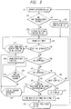
- Fig. 2 shows an enlarged view of the console unit 12 of Fig. 1.
- the arrangement of Fig. 2 is based on an arrangement of a conventional facsimile machine.
- Numeral 21 denotes an LCD panel through which the proceeding of the operation and the operation of the facsimile machine are informed to a user
- numeral 22 denote registration keys which are used to register functions selected by the user
- numeral 23 denotes a ten-key which is used to enter a telephone number.
- Any number of registration keys 22 may be provided.
- Numeral 24 denotes a set key for setting a mode for the registration
- numeral 25 denotes a clear key for clearing the registered mode
- numeral 26 denotes a selection key for selecting a desired one of several registration modes.
- Numeral 27 denotes one-touch keys. By depressing one of the keys 27, a telephone number stored in the RAM 15 is called.
- Numeral 28 denotes a stop key which is used to terminate the operation of the facsimile machine
- numeral 29 denotes a start key to start a predetermined operation (such as transmission, reception or copy).
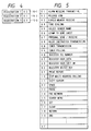
- Fig. 4 shows a data store area in the RAM 15 of key function numbers registered in the registration keys 22.
- Fig. 5 shows a list of the registered key function number data and the corresponding function data.
- the key function numbers 01 to 2F are preregistered, and the key function numbers 30 to 4F are reserved for use for the function expansion.
- the operator selects any desired key function numbers from the key function number data and register them in 15-1, 15-2 and 15-3 of Fig. 4.
- the function corresponding to the key function number 01 is, for example, the selection of alarm mode for missing transmittal.
- the alarm mode for the missing transmittal if the number of sheets manually entered by the operator is different from the number of sheets actually transmitted, it is informed to the operator.
- ECM error correction mode
- a forced memory receive mode is selected so that the received image is temporarily stored in the memory, and after the reception the image is read and printed out.
- a dialing signal is switched from a pulse signal to a tone signal.
- a sender name which the operator desires is selected from a plurality of preregistered sender names.
- a mode to stamp to the transmitted document sheet is selected.
- a personal receive/personal transmit mode is selected.
- a timer transmission/timer multi-address calling mode is selected.
- a timer polling receive/timer multi-polling receive mode is selected.
- a mode to register a telephone number to a one-touch dialing key or a present dialing key is selected.
- a mode to register a user telephone number or user abbreviation data is selected.
- a mode to register data to a user soft switch is selected.
- a mode to register data to a select button (not shown) is selected.
- a report output mode to record various reports such as a communication management report is selected.
- a pause is inserted in the calling telephone number.
- a telephone number of a data communication network is sent where the data communication network is used.
- the registered data or menus are searched.
- the data is cleared if wrong digits or characters are registered.
- Fig. 3 shows a registration control process of the registration key 22 by the CPU 11 of the machine shown in Figs. 1 and 2.
- the process is stored in the ROM 14 as the control program for the CPU 11.
- step S31 one of the registration keys 22 is depressed.
- step S32 whether any function has been registered in the depressed key or not is determined (00 indicates no registration of the function).
- step S33 the function is displayed on the LCD panel 21 (step S33) and the process stands by a key entry in a step S35. If no function has been registered, selectable functions are displayed on the LCD panel 21 (step S34) and the process proceeds to the step S35.
- a step S36 if the depressed key is the selection key 26, one of the functions is selected by scrolling the function menu shown in Fig. 5 in a step S37 and the process returns to the step S35.
- a step S38 if the depressed key is the clear key 25, whether anything has been registered to the registration key to which a function is to be registered or not is determined in a step S39.
- step S40 the memory area of the RAM 15 in which the function has been stored is cleared in a step S40, and the process proceeds to a step S37. If nothing has been registered, the process directly proceeds to the step S37.
- a step S41 if the depressed key is the set key 24, whether the selected function to be registered has been registered to other registration key or not is determined in a step S42. If it has been registered, "Already registered in registration key 00" is displayed on the LCD panel 21 in a step S43 and the process proceeds to the step S37.
- step S42 if the selected function has not been registered in any registration key, the process proceeds to a step S44 to store the data of the key function number corresponding to the selected function in the memory area of the RAM 15 shown in Fig. 4.
- step S45 "Registered" is displayed on the LCD panel 21 and the process returns to the step S31.
- a key entry time is managed, and if no key is depressed in a predetermined time period, the key entry timer is timed out and the process stands by in a step S47.
- Fig. 6 shows a flow chart of a key entry control operation when the registration key 22 is depressed.
- a step S50 the presence or absence of key entry is determined. If there is key entry and if there is a key entry for one of the registrations 1, 2 and 3 in steps S51, S52 and S53, the process proceeds to a step S55 and the data of the key function number corresponding to the registration keys is read from the RAM 15. If the entry key is other than the registration keys 22, the process proceeds from the step S53 to a step S54 and executes the process for the key entry.
- step S55 the key function number data is read from the RAM 15.
- step S56 whether the key function number data is "00" or not is determined. If it is "00", it means that the key function has not been registered and the unregistration of the depressed registration key is displayed on the LCD 21 in a step S57. Then, the process is terminated.
- step S56 if the key function number data is not "00", the data of the key function corresponding to the key function number data is read from the area of the RAM 15 shown in Fig. 5 in a step S58 and the data of the key function is displayed on the LCD 21. In a step S59, the key function is processed.
- the key function data "02" of Fig. 5 is read and the ECM release mode to inhibit the ECM is selected. Accordingly, in this case, the registration 1 key functions as an ECM release key.
- the user selects the functions which user may frequently use and registers those functions in the registration keys. Accordingly the operation is simplified, the number of keys in the console panel is reduced and the reduction of the cost and size of the machine is facilitated.
- the set key 24 and the clear key 25 are separately arranged although those keys may be shared with the start key 28 and the stop key 29. In this case, the keys on the console panel can be further reduced and the further reduction of the cost and size is attained.
Description
- The present invention relates to a facsimile apparatus, and more particularly to a facsimile apparatus having a console unit, such as key entry switches, for selecting one of various functions.
- Various electronic equipments have recently been advanced in functions and performances. A facsimile machine is not the exception and a number of functions which have not been found in the prior facsimile machines are being attained.
- As a result, an operation method or operation procedure of the machine is becoming fairly complex.
- As to the operation method, there is a design philosophy that a number of functions are assigned to respective keys. In this case, however, the number of keys in a console panel increases very much.
- In another design philosophy, key(s) for shifting or changing operation modes is provided and a plurality of functions are assigned to each key. In this case, the number of keys may be reduced but a complex operation is required to attain the same additional functions.
- Those two prior design philosqphies include the following problems.
- 1) In the former design philosophy, a number of keys are required for the console unit and the cost and the size of the machine increase. From the standpoint of users, only a small number of users utilize all functions of the recent high performance machine. Thus, the keys which are not normally used by the users are arranged on the console panel and the space is wasted.
- 2) In the latter design philosophy, the number of keys can be reduced but when the user wants to select a desired function, the operation is complex and an excessive burden is imported to the user, or the function may not be actually used by the user even if the function is very useful to the user.
- Applications relating to keys include USP 4,502,080, USP 4,567,322, USP 4,729,033, USP 4,833,705, and USP 4,908,853, but none of them solve the problems described above.
- JP-A-58161468 discloses an image processing system which uses "soft keys" for performing functions, in accordance with the second "design philosophy" mentioned above. In this system, depression of a key results in the function listed on a display above the key being carried out. The function to be performed can be changed by using a further key to select different functions to be listed on the display, or by pressing the key itself, since a new function is displayed once the previous function has been performed.
- According to the invention, there is provided a facsimile apparatus as set out in
claim 1. - An embodiment of the present invention provides an improved communication apparatus.
- An embodiment of the present invention provides a facsimile apparatus equipped with key entry switches whose function can be set by a user as desired.
- Embodiments of the present invention will now be described with reference to the accompanying drawings, in which:
- Fig. 1 shows a block diagram of a configuration of a facsimile machine in accordance with one embodiment of the present invention,
- Fig. 2 shows a console unit of the facsimile machine,
- Fig. 3 shows a flow chart of key function registration in the embodiment,
- Fig. 4 shows a function registration area for a
registration key 22 in aRAM 15, - Fig. 5 shows a store area of key function data corresponding to key function numbers in the
RAM 15, and - Fig. 6 shows a flow chart of a key entry routine of the
registration key 22. - Embodiments of the present invention are now explained in detail with reference to the accompanying drawings. In the embodiment, a facsimile machine is described as the communication apparatus.
- Fig. 1 shows a configuration of a facsimile machine in accordance with an embodiment of the present invention.
- In Fig. 1,
numeral 11 denotes a CPU which may comprise a microprocessor, andnumeral 12 denotes a console unit of the embodiment. - The machine is operated by an input from the console unit. Numeral 13 denotes a main power supply which supplies voltages 5V, ±12V and 24V required by individual system circuits. Numeral 14 denotes a ROM in which a main software program of the machine is stored. A program of an embodiment of the present invention shown in Fig. 3 is also stored in the
ROM 14. - Numeral 15 denotes a RAM which is used as a memory for storing various data. Functions assigned to registration keys in the present invention are stored in the
RAM 15. Numeral 16 denotes a battery for backing up the data of theRAM 15 even in an off-state of thepower supply 13. - Fig. 2 shows an enlarged view of the
console unit 12 of Fig. 1. The arrangement of Fig. 2 is based on an arrangement of a conventional facsimile machine. Numeral 21 denotes an LCD panel through which the proceeding of the operation and the operation of the facsimile machine are informed to a user,numeral 22 denote registration keys which are used to register functions selected by the user, andnumeral 23 denotes a ten-key which is used to enter a telephone number. - Any number of
registration keys 22 may be provided. Numeral 24 denotes a set key for setting a mode for the registration,numeral 25 denotes a clear key for clearing the registered mode, andnumeral 26 denotes a selection key for selecting a desired one of several registration modes. Numeral 27 denotes one-touch keys. By depressing one of thekeys 27, a telephone number stored in theRAM 15 is called. - Numeral 28 denotes a stop key which is used to terminate the operation of the facsimile machine, and
numeral 29 denotes a start key to start a predetermined operation (such as transmission, reception or copy). - Fig. 4 shows a data store area in the
RAM 15 of key function numbers registered in theregistration keys 22. Fig. 5 shows a list of the registered key function number data and the corresponding function data. - In the present embodiment, the
key function numbers 01 to 2F are preregistered, and the key function numbers 30 to 4F are reserved for use for the function expansion. The operator selects any desired key function numbers from the key function number data and register them in 15-1, 15-2 and 15-3 of Fig. 4. - The function corresponding to the
key function number 01 is, for example, the selection of alarm mode for missing transmittal. In the alarm mode for the missing transmittal, if the number of sheets manually entered by the operator is different from the number of sheets actually transmitted, it is informed to the operator. - In the
key function number 02, if a transmission error occurs, an error correction mode (ECM) is inhibited (ECM release) to prevent the selection of the ECM in which error data is automatically resent. - In the
key function number 03, a forced memory receive mode is selected so that the received image is temporarily stored in the memory, and after the reception the image is read and printed out. - In the
key function number 04, a dialing signal is switched from a pulse signal to a tone signal. - In the key function number 05, a sender name which the operator desires is selected from a plurality of preregistered sender names.
- In the
key function number 06, a mode to stamp to the transmitted document sheet is selected. - In the
key function number 07, a personal receive/personal transmit mode is selected. - In the
key function number 08, a relay instructed transmission mode is selected. - In the key function number 09, a timer transmission/timer multi-address calling mode is selected.
- In the key function number 0A, a timer polling receive/timer multi-polling receive mode is selected.
- In the key function number 0B, a mode to register a telephone number to a one-touch dialing key or a present dialing key is selected.
- In the key function number 0C, a mode to register a user telephone number or user abbreviation data is selected.
- In the key function number 0D, a mode to register data to a user soft switch is selected.
- In the key function number 0E, a mode to register data to a select button (not shown) is selected.
- In the key function number 0F, a report output mode to record various reports such as a communication management report is selected.
- In the key function number 10, the multi-address calling is stopped.
- In the
key function number 11, a cursor on theLCD panel 21 is moved. - In the
key function number 12, a space is inserted between digits or characters to be registered. - In the
key function number 13, a pause is inserted in the calling telephone number. - In the
key function number 14, a telephone number of a data communication network is sent where the data communication network is used. - In the
key function number 15, the registered data or menus are searched. - In the
key function number 16, the items are set. - In the key function number 17, the data is cleared if wrong digits or characters are registered.
- In the key function number 18, the registration of the current item is terminated and the registration of the next item is started.
- In the
key function number 19, the registration of data is terminated. - Other various key functions as well as their function numbers are also registered in the
RAM 15. - Fig. 3 shows a registration control process of the
registration key 22 by theCPU 11 of the machine shown in Figs. 1 and 2. The process is stored in theROM 14 as the control program for theCPU 11. - In a step S31, one of the
registration keys 22 is depressed. In a step S32, whether any function has been registered in the depressed key or not is determined (00 indicates no registration of the function). - If it has been registered, the function is displayed on the LCD panel 21 (step S33) and the process stands by a key entry in a step S35. If no function has been registered, selectable functions are displayed on the LCD panel 21 (step S34) and the process proceeds to the step S35.
- In a step S36, if the depressed key is the
selection key 26, one of the functions is selected by scrolling the function menu shown in Fig. 5 in a step S37 and the process returns to the step S35. In a step S38, if the depressed key is theclear key 25, whether anything has been registered to the registration key to which a function is to be registered or not is determined in a step S39. - If something has been registered, the memory area of the
RAM 15 in which the function has been stored is cleared in a step S40, and the process proceeds to a step S37. If nothing has been registered, the process directly proceeds to the step S37. - In a step S41, if the depressed key is the set
key 24, whether the selected function to be registered has been registered to other registration key or not is determined in a step S42. If it has been registered, "Already registered in registration key 00" is displayed on theLCD panel 21 in a step S43 and the process proceeds to the step S37. - In the step S42, if the selected function has not been registered in any registration key, the process proceeds to a step S44 to store the data of the key function number corresponding to the selected function in the memory area of the
RAM 15 shown in Fig. 4. In a step S45, "Registered" is displayed on theLCD panel 21 and the process returns to the step S31. - In a step S46, a key entry time is managed, and if no key is depressed in a predetermined time period, the key entry timer is timed out and the process stands by in a step S47.
- Fig. 6 shows a flow chart of a key entry control operation when the
registration key 22 is depressed. - In a step S50, the presence or absence of key entry is determined. If there is key entry and if there is a key entry for one of the
registrations RAM 15. If the entry key is other than theregistration keys 22, the process proceeds from the step S53 to a step S54 and executes the process for the key entry. - In the step S55, the key function number data is read from the
RAM 15. In a step S56, whether the key function number data is "00" or not is determined. If it is "00", it means that the key function has not been registered and the unregistration of the depressed registration key is displayed on theLCD 21 in a step S57. Then, the process is terminated. - In the step S56, if the key function number data is not "00", the data of the key function corresponding to the key function number data is read from the area of the
RAM 15 shown in Fig. 5 in a step S58 and the data of the key function is displayed on theLCD 21. In a step S59, the key function is processed. - Assuming that the key function number data shown in Fig. 4 has been registered in the
registration 1 key and theregistration 1 key is depressed, the key function data "02" of Fig. 5 is read and the ECM release mode to inhibit the ECM is selected. Accordingly, in this case, theregistration 1 key functions as an ECM release key. - In accordance with the present embodiment, the user selects the functions which user may frequently use and registers those functions in the registration keys. Accordingly the operation is simplified, the number of keys in the console panel is reduced and the reduction of the cost and size of the machine is facilitated.
- Since the user may select the functions which the user really desires to use out of the added functions of the facsimile machine, a small number of keys on the console panel may be effectively utilized, the waste is eliminated, the practice to operate the machine is ready, and the desired function can be inputted by a very simple operation.
- In the above embodiment, the
set key 24 and theclear key 25 are separately arranged although those keys may be shared with thestart key 28 and thestop key 29. In this case, the keys on the console panel can be further reduced and the further reduction of the cost and size is attained. - The present invention is not limited to the above embodiment but various modifications thereof may be made.
Claims (8)
- A facsimile apparatus having a predefined repertoire of facsimile communication functions, a plurality of which are not assigned to a dedicated apparatus key;
characterised by:at least one function key (22) for performing a single user-assigned function, the number of function keys being less than the number of functions in the plurality;selecting means (24, 25, 26) for allowing a user to select from a display a desired one function from said plurality to be permanently associated with a function key; andmemory means (15) for storing the association between each key and the respective selected function so that, in use, the apparatus performs only the appropriate selected function in response to future operations of the associated key. - An apparatus according to claim 1, wherein said selecting means includes a select key (26) for selecting one of said plurality of functions, and a set key (24), the operation of which when a function has been selected using said select key causes said association to be stored in said memory means.
- An apparatus according to any preceding claim, further comprising means (25) for clearing the association stored in said memory means, so that said key has no function associated with it.
- An apparatus according to any preceding claim, further comprising means for changing the association stored in said memory means, so that said key thereafter has a different function associated with it.
- An apparatus according to any preceding claim, further comprising display means (21) for displaying the association stored in said memory means.
- An apparatus according to any preceding claim having a plurality of function keys, and wherein said selecting means is operable to allow a user to select a respective function from said plurality to be associated with each function key, and wherein said memory means is operable to store the association between each key and the respective selected function so that the apparatus performs the appropriate selected function in response to operation of the associated key.
- An apparatus according to claim 5, further comprising means for checking whether a function has already been associated with a key.
- An apparatus according to any preceding claim, operable to allow the number of functions in said plurality to be increased.
Applications Claiming Priority (2)
| Application Number | Priority Date | Filing Date | Title |
|---|---|---|---|
| JP3729290 | 1990-02-20 | ||
| JP37292/90 | 1990-02-20 |
Publications (3)
| Publication Number | Publication Date |
|---|---|
| EP0443804A2 EP0443804A2 (en) | 1991-08-28 |
| EP0443804A3 EP0443804A3 (en) | 1992-04-01 |
| EP0443804B1 true EP0443804B1 (en) | 1997-04-23 |
Family
ID=12493634
Family Applications (1)
| Application Number | Title | Priority Date | Filing Date |
|---|---|---|---|
| EP91301289A Expired - Lifetime EP0443804B1 (en) | 1990-02-20 | 1991-02-19 | Facsimile apparatus |
Country Status (4)
| Country | Link |
|---|---|
| US (1) | US5784009A (en) |
| EP (1) | EP0443804B1 (en) |
| DE (1) | DE69125741T2 (en) |
| ES (1) | ES2100206T3 (en) |
Families Citing this family (5)
| Publication number | Priority date | Publication date | Assignee | Title |
|---|---|---|---|---|
| JP2715889B2 (en) * | 1993-12-24 | 1998-02-18 | 日本電気株式会社 | Printer with facsimile function |
| KR970014086A (en) * | 1995-08-24 | 1997-03-29 | 구자홍 | How to set your fax's features |
| DE19619975C1 (en) * | 1996-05-17 | 1997-09-11 | Daimler Benz Ag | Hand transmitter operating method for vehicle remote control |
| KR100334806B1 (en) | 1999-12-07 | 2002-05-02 | 윤종용 | Method of hot key user assignment in mobile communication terminal |
| US7533067B2 (en) * | 2005-06-30 | 2009-05-12 | Pitney Bowes Inc. | Control panel label for a postage printing device |
Family Cites Families (9)
| Publication number | Priority date | Publication date | Assignee | Title |
|---|---|---|---|---|
| JPH0634498B2 (en) * | 1982-03-19 | 1994-05-02 | キヤノン株式会社 | Information processing equipment |
| JPS59189770A (en) * | 1983-04-12 | 1984-10-27 | Canon Inc | Operating device |
| JPS61290520A (en) * | 1985-06-19 | 1986-12-20 | Nippon Texas Instr Kk | Electronic equipment |
| EP0272070B1 (en) * | 1986-12-15 | 1995-03-01 | Omron Corporation | Input apparatus for computer |
| JPS63300655A (en) * | 1987-05-29 | 1988-12-07 | Canon Inc | Dialing equipment |
| FR2616243B1 (en) * | 1987-06-05 | 1992-07-24 | Thomson Csf | MODIFIABLE CONFIGURATION KEYBOARD |
| US4825200A (en) * | 1987-06-25 | 1989-04-25 | Tandy Corporation | Reconfigurable remote control transmitter |
| US4870677A (en) * | 1987-09-04 | 1989-09-26 | Copytele, Inc. | Data/facsimile telephone subset apparatus incorporating electrophoretic displays |
| PT89295A (en) * | 1987-12-22 | 1989-09-14 | Autophon Ascom Ag | FILE OF TELEPHONE SUBSCRIBERS WITH AUTOMATIC CHOOSING DEVICE FOR ADAPTING TELEPHONE APPARATUS |
-
1991
- 1991-02-19 ES ES91301289T patent/ES2100206T3/en not_active Expired - Lifetime
- 1991-02-19 DE DE69125741T patent/DE69125741T2/en not_active Expired - Fee Related
- 1991-02-19 EP EP91301289A patent/EP0443804B1/en not_active Expired - Lifetime
-
1994
- 1994-08-26 US US08/296,974 patent/US5784009A/en not_active Expired - Lifetime
Also Published As
| Publication number | Publication date |
|---|---|
| US5784009A (en) | 1998-07-21 |
| EP0443804A2 (en) | 1991-08-28 |
| DE69125741D1 (en) | 1997-05-28 |
| ES2100206T3 (en) | 1997-06-16 |
| DE69125741T2 (en) | 1997-10-02 |
| EP0443804A3 (en) | 1992-04-01 |
Similar Documents
| Publication | Publication Date | Title |
|---|---|---|
| US5555104A (en) | Operation unit of electronic equipment utilizing visually displayed functions on a touch screen | |
| EP1777936A1 (en) | Multi function peripheral | |
| GB2312131A (en) | Broadcast transmission in a facsimile system | |
| EP0649243B1 (en) | Facsimile unit | |
| JP2005018607A (en) | Remote control device and remote control system | |
| EP0443804B1 (en) | Facsimile apparatus | |
| JPH1079819A (en) | Composite machine | |
| US6501835B2 (en) | Facsimile having user interface with keys that enable undo, yes, no and report functions | |
| US5917613A (en) | Facsimile having a multi-path, context interpretive, user interface | |
| JP3080321B2 (en) | Communication device | |
| US6700959B2 (en) | Facsimile machine | |
| JP3415415B2 (en) | Facsimile machine with broadcast transmission confirmation function | |
| JP3003778B2 (en) | Telephone device compatible with telephone number notification service | |
| JPH09135318A (en) | Facsimile equipment | |
| JP2963167B2 (en) | Destination search device | |
| JP2868953B2 (en) | Facsimile machine | |
| JPH04172753A (en) | Facsimile equipment | |
| JPH04245763A (en) | Facsimile equipment | |
| JP2002314671A (en) | Communication terminal | |
| JPH098895A (en) | Communication equipment | |
| JPH077592A (en) | Facsimile equipment | |
| JPH0613259U (en) | Fax machine | |
| JP2002314670A (en) | Communication terminal device | |
| JPH04176256A (en) | Facsimile equipment | |
| JPH0723154A (en) | Facsimile equipment |
Legal Events
| Date | Code | Title | Description |
|---|---|---|---|
| PUAI | Public reference made under article 153(3) epc to a published international application that has entered the european phase |
Free format text: ORIGINAL CODE: 0009012 |
|
| AK | Designated contracting states |
Kind code of ref document: A2 Designated state(s): DE ES FR GB IT |
|
| PUAL | Search report despatched |
Free format text: ORIGINAL CODE: 0009013 |
|
| AK | Designated contracting states |
Kind code of ref document: A3 Designated state(s): DE ES FR GB IT |
|
| 17P | Request for examination filed |
Effective date: 19920817 |
|
| 17Q | First examination report despatched |
Effective date: 19940506 |
|
| GRAG | Despatch of communication of intention to grant |
Free format text: ORIGINAL CODE: EPIDOS AGRA |
|
| GRAH | Despatch of communication of intention to grant a patent |
Free format text: ORIGINAL CODE: EPIDOS IGRA |
|
| GRAH | Despatch of communication of intention to grant a patent |
Free format text: ORIGINAL CODE: EPIDOS IGRA |
|
| GRAA | (expected) grant |
Free format text: ORIGINAL CODE: 0009210 |
|
| AK | Designated contracting states |
Kind code of ref document: B1 Designated state(s): DE ES FR GB IT |
|
| ITF | It: translation for a ep patent filed |
Owner name: SOCIETA' ITALIANA BREVETTI S.P.A. |
|
| REF | Corresponds to: |
Ref document number: 69125741 Country of ref document: DE Date of ref document: 19970528 |
|
| REG | Reference to a national code |
Ref country code: ES Ref legal event code: FG2A Ref document number: 2100206 Country of ref document: ES Kind code of ref document: T3 |
|
| ET | Fr: translation filed | ||
| PLBE | No opposition filed within time limit |
Free format text: ORIGINAL CODE: 0009261 |
|
| STAA | Information on the status of an ep patent application or granted ep patent |
Free format text: STATUS: NO OPPOSITION FILED WITHIN TIME LIMIT |
|
| 26N | No opposition filed | ||
| REG | Reference to a national code |
Ref country code: GB Ref legal event code: IF02 |
|
| PGFP | Annual fee paid to national office [announced via postgrant information from national office to epo] |
Ref country code: ES Payment date: 20090108 Year of fee payment: 19 |
|
| PGFP | Annual fee paid to national office [announced via postgrant information from national office to epo] |
Ref country code: DE Payment date: 20090228 Year of fee payment: 19 |
|
| PGFP | Annual fee paid to national office [announced via postgrant information from national office to epo] |
Ref country code: GB Payment date: 20090218 Year of fee payment: 19 |
|
| PGFP | Annual fee paid to national office [announced via postgrant information from national office to epo] |
Ref country code: IT Payment date: 20090205 Year of fee payment: 19 |
|
| PGFP | Annual fee paid to national office [announced via postgrant information from national office to epo] |
Ref country code: FR Payment date: 20090223 Year of fee payment: 19 |
|
| GBPC | Gb: european patent ceased through non-payment of renewal fee |
Effective date: 20100219 |
|
| REG | Reference to a national code |
Ref country code: FR Ref legal event code: ST Effective date: 20101029 |
|
| PG25 | Lapsed in a contracting state [announced via postgrant information from national office to epo] |
Ref country code: FR Free format text: LAPSE BECAUSE OF NON-PAYMENT OF DUE FEES Effective date: 20100301 |
|
| PG25 | Lapsed in a contracting state [announced via postgrant information from national office to epo] |
Ref country code: DE Free format text: LAPSE BECAUSE OF NON-PAYMENT OF DUE FEES Effective date: 20100901 |
|
| REG | Reference to a national code |
Ref country code: ES Ref legal event code: FD2A Effective date: 20110222 |
|
| PG25 | Lapsed in a contracting state [announced via postgrant information from national office to epo] |
Ref country code: GB Free format text: LAPSE BECAUSE OF NON-PAYMENT OF DUE FEES Effective date: 20100219 Ref country code: IT Free format text: LAPSE BECAUSE OF NON-PAYMENT OF DUE FEES Effective date: 20100219 |
|
| PG25 | Lapsed in a contracting state [announced via postgrant information from national office to epo] |
Ref country code: ES Free format text: LAPSE BECAUSE OF NON-PAYMENT OF DUE FEES Effective date: 20110220 |