EP0443749A2 - Cigarette or cigar - Google Patents
Cigarette or cigar Download PDFInfo
- Publication number
- EP0443749A2 EP0443749A2 EP91300968A EP91300968A EP0443749A2 EP 0443749 A2 EP0443749 A2 EP 0443749A2 EP 91300968 A EP91300968 A EP 91300968A EP 91300968 A EP91300968 A EP 91300968A EP 0443749 A2 EP0443749 A2 EP 0443749A2
- Authority
- EP
- European Patent Office
- Prior art keywords
- cigarette
- control element
- tobacco rod
- smoke
- flow
- Prior art date
- Legal status (The legal status is an assumption and is not a legal conclusion. Google has not performed a legal analysis and makes no representation as to the accuracy of the status listed.)
- Withdrawn
Links
Images


Classifications
-
- A—HUMAN NECESSITIES
- A24—TOBACCO; CIGARS; CIGARETTES; SIMULATED SMOKING DEVICES; SMOKERS' REQUISITES
- A24D—CIGARS; CIGARETTES; TOBACCO SMOKE FILTERS; MOUTHPIECES OF CIGARS OR CIGARETTES; MANUFACTURE OF TOBACCO SMOKE FILTERS OR MOUTHPIECES
- A24D1/00—Cigars; Cigarettes
-
- A—HUMAN NECESSITIES
- A24—TOBACCO; CIGARS; CIGARETTES; SIMULATED SMOKING DEVICES; SMOKERS' REQUISITES
- A24D—CIGARS; CIGARETTES; TOBACCO SMOKE FILTERS; MOUTHPIECES OF CIGARS OR CIGARETTES; MANUFACTURE OF TOBACCO SMOKE FILTERS OR MOUTHPIECES
- A24D3/00—Tobacco smoke filters, e.g. filter tips or filtering inserts; Filters specially adapted for simulated smoking devices; Mouthpieces of cigars or cigarettes
- A24D3/04—Tobacco smoke filters characterised by their shape or structure
- A24D3/043—Tobacco smoke filters characterised by their shape or structure with ventilation means, e.g. air dilution
Definitions
- This invention relates to a cigarette or cigar which is arranged to have an increasing level of tip air ventilation as it is smoked.
- the purpose of the present invention is to avoid any untoward increase in the strength of later puffs and improve the uniformity of the strength and flavour of the smoke throughout smoking by the provision of an increased level of air dilution of the smoke in the later puffs.
- cigarette will be used although it will be understood that the term is meant to also include a cigar, cigarlette or other similar type of smoking product.
- a cigarette comprises a tobacco rod and means for introducing a flow of ambient diluting air into the smoke stream passing to the smoker after a predetermined length of the tobacco rod has been smoked, said means including a flow path for ambient diluting air which is sealed by a low melting point material and control means for utilising the heat from the glowing tip of the cigarette when it reaches a predetermined point in the length of the tobacco rod to melt said low melting point material to introduce or increase a flow of diluting ambient air into the smoke stream downstream of the glowing tip.
- the glowing tip operates the means to introduce or increase a flow of diluting air into the cigarette for the later puffs.
- the flow path can be provided in a control element located at the end of the tobacco rod spaced away from the end to be ignited.
- control means includes an axially aligned combustible tube in said tobacco rod which acts to convey heat from the glowing tip to the low melting point material after a predetermined length of the cigarette has been smoked.
- the combustible tube acts to concentrate hot gases from the tip in order to melt the low melting point material. This occurs when the combustion cone reaches the vicinity of the end of the tube and at that time the flow of combustion product is split so that a portion flows down the tube and a portion flows through the tobacco rod.
- the split depends on the relative resistances of the two pathways. There is a rapid fall in temperature of the smoke during its passage through the tobacco rod but the smoke and air passes down the tube at a high velocity and retains a relatively high temperature where it exits onto the end of the control element.
- the flow passage can extend from the outer circumference of the cigarette to the tobacco rod upstream of the control element, or to a smoke passage provided in the control element and which is sealed by said low melting point material, said flow path extending from the outer circumference of the cigarette to said smoke passage.
- At least one additional smoke passage is provided which is open to smoke flow from the tobacco rod prior to the melting of the low melting point material and the opening of the smoke passage.
- the combustible tube can be arranged in various positions in the tobacco rod, for example, it can be to one side thereof or it can be co-axial therewith.
- the control element can be made from a rigid non-pervious material, for example metal or carbon, but is preferably made from a plastics material, for example polyethylene, polypropylene, cellulose acetate or nylon.
- the body of the element may be solid or, if desired, may be hollow provided the necessary flow channels are maintained discrete.
- control element can be made from a filter material, for example cellulose acetate, polyethylene or polypropylene fibre tow or web, or paper.
- a filter material for example cellulose acetate, polyethylene or polypropylene fibre tow or web, or paper.
- the control element can itself form the mouthpiece end of the cigarette or, alternatively, a conventional filter element can be employed downstream of it to provide the mouthpiece end.
- the tobacco rod of a cigarette is provided with an axially aligned combustible tube which is shorter than the tobacco rod and is positioned with one end adjacent to a control element.
- This element is provided with a flow path or paths for the introduction of ambient diluting air through which, initially, the flow is restricted or completely arrested by a film of low melting point, impermeable material forming a seal across the potential pathways.
- This film, or a region of it is situation in close proximity to the end of the tube in the tobacco rod.
- Air dilution of the smoke is introduced or increased during smoking when the burning zone of the tobacco rod reaches the tube and hot air and/or smoke passes along the tube, melts the low-melting film and, thus, opens up the ventilation flow path.
- a cigarette according to the invention comprises a tobacco rod 1 wrapped in cigarette paper 2 attached to a two part filter, indicated generally by reference numeral 3, by a tipping paper 4.
- An axially aligned tube 5 is located within the tobacco rod 1 with one end 6 adjacent to the two part filter rod 3 and the other end 7 is situated within the tobacco column.
- the end 7 may be either open or sealed.
- the length of the tube 5 is less than that of the tobacco rod, for example, between 10% and 90% and more preferably between 10% and 60% of the length of the tobacco rod.
- the diameter of the tube is between 0.2 mm and 4 mm, preferably between 0.5 mm and 2.5 mm and more preferably between 1.0 mm and 2.0 mm.
- This tube is constructed from a combustible material, for example paper, cardboard or reconstituted tobacco sheet having a permeability of less than 100 cm/min cbar, preferably of less than 50 cm/min cbar.
- the two part filter rod comprises means for introducing a flow of ambient diluting air in the form of a control element 8 and a filter element 9 made from conventional filter material.
- the two parts are held together by a plug wrap 10.
- the control element 8 is substantially cylindrical and has a central smoke channel 11.
- the upstream end of the element is formed with an annular recess 12 so that the smoke channel 11 is continued by walls 13.
- the recess 12 has one or more radially extending holes 14 in the peripheral region which register with holes or porous regions 15 in the tipping paper 4 and plug wrap 10 to provide flow paths for ambient air to become entrained with the smoke when heated air and/or smoke exiting the tube 5 at end 6 melts a film of low melting material 16 which extends over the face of the annular recess 12.
- the upstream end 17 of the channel 11 is open the channel 11 provides a flow path for smoke throughout the smoking of the cigarette.
- a second flow path for ambient diluting air is opened up which extends through the air holes 14 axially through the annular recess 12 into the tobacco rod 1 upstream of the control element 8 and then into the central smoke passage 11.
- control element 9 may be constructed from any appropriate rigid material such as metal or carbon, but preferably a synthetic plastics material is employed, for example polyethylene, polypropylene, cellulose acetate or nylon.
- a synthetic plastics material for example polyethylene, polypropylene, cellulose acetate or nylon.
- the body of the element is solid but, if desired it could be hollow provided the necessary flow paths are maintained discrete.
- control element 18 has a smoke flow passage 19, the ends 20 and 21 of which are closed by a film of low melting point material. Radially extending air flow passages 22 are provided and an additional smoke flow passage 23 extends through the element.
- the tube 5 is co-axial with the tobacco rod 1 and the cigarette end 6 is aligned with the smoke flow passage 19.
- the air flow passages 22 connect the passage 19 to the curved surface of the element where they register with holes or porous regions 15 in the tipping paper 4 to provide the air flow paths.
- both ends of the passage 19 are shown as being sealed, only the end 20 may be sealed if desired.
- Vents 22 When the hot gases in the tube 5 melt the sealing film, ventilation through the passages 22 is provided. Two or more additional passages 23 may be provided to allow smoke passage through the control element into the filter element 9 prior to the opening of the passage 19.
- FIGS 7, 8 and 9 show another construction of control element and once again the same reference numerals are used to indicate similar parts as in the other figures.
- the tube 5 is again adjacent the wall of the tobacco rod 1 but the control element 25 comprises a plug of filter material 26 which is annular in cross-section and held in place on the outside by the porous or perforated plug wrap 10.
- the filter material 26 surrounds an impermeable tube 27 having open ends 28 and 29 and the face of the annular plug 26 adjacent the tobacco rod 1 is sealed, initially, by a film of low melting material 30.
- the other end of the plug may be sealed by a film of the same material or by other means 31.
- the tube 27 provides a passage 32 for smoke and maybe empty or may contain a filter material (not shown) similar to or different from the plug 26. Ventilation is achieved through perforations or porous regions 15 in the tipping paper 4 and plug wrap 10 and is introduced or increased when the film 30, and film 31, when provided, melts through contact with hot air and/or smoke drawn through the tube 5 in the tobacco rod. Thus once again a flow path for ambient ventilating air is provided, in this case into the control element itself and then into the filter element 9.
- FIGs 10, 11 and 12 show another construction in which the same reference numerals are once again used to indicate similar parts to those shown in the other Figures.
- the tube 5 is again positioned along the central axis of the tobacco rod 1 but the control element 35 comprises an annular plug of filter material wrapped on the outside by the porous or perforated plug wrap 10.
- the annular plug of filter material surrounds an impermeable tube 36 one end of the tube being sealed initially by a film of low melting material 37 and, optionally, the other end of the tube 36 may be sealed by a film 38 of the same material or by other means.
- the tube 36 can be empty or may contain a filter material 39 as shown in the drawing which is similar to or different from the filter material comprising the plug.
- One or more air passages 40 are provided connecting the tube 36 to the curved surface of the plug and these register with holes or porous regions 15 in the tipping paper 4 and plug wrap 10.
- the plug of filter material provides the flow path for smoke and ambient air ventilation is introduced or increased when the film 37, and the film 38, when provided, melt through contact with hot air and/or smoke drawn through the tube 5 in the tobacco rod 1.
- the tube 32 shown in Figure 7 and the tube 36 shown in Figure 10 may be made from any suitable material such as polyethylene, polypropylene, cellulose acetate, nylon or other synthetic plastics material.
- the filter material used in the control elements shown in Figures 7 and 10 may be of any commonly used materials, for example cellulose acetate, polyethylene or polypropylene fibre tow or web, or paper.
- the low melting material employed to form a film in all the embodiments described can have a melting point below 150° C and preferably below 1OO ⁇ C and more preferably below 70 C. Hot melt adhesives of melting point around 60 C have been found to be suitable.
- the additional filter element 9 is included but if desired this could be omitted so that the control element forms the mouthpiece of the cigarette.
- An example of a cigarette made according to the invention is as follows :
- An axial central hole (1.0 mm diameter) and an annular recess (inner diameter 3.0 mm, outer diameter 6.0 mm) were cut into a nylon cylinder ( 8 mm diameter, 23.0 mm length).
- the axial hole extended the whole length of the cylinder whilst the recess was cut commencing at a flat face to a depth of 8.0 mm.
- Six ventilation holes (each 0.8 mm diameter) were drilled equidistant around the circumference of the cylinder through the outer wall of the recess at a distance of 7.0 mm from the face.
- a thin film of hot melt adhesive (melting point around 60 C) was applied to cover the annular opening of the recess.
- Cigarettes were constructed from the control element by attaching separately 64 mm tobacco rods, containing a cylindrical empty paper tube (42 mm long, 2.0 mm diameter), to the end with the hot melt adhesive and 20 mm cellulose acetate filters to the other end.
- the paper tube was located at the periphery of the tobacco rod with one end adjacent to the control element and the other end, which was sealed by crimping, at a position 22 mm from the lit end.
- the cigarettes were tested using a vacuum driven smoking machine set to take 35 ml square-wave puffs of duration 2 seconds at a frequency of one puff per minute.
- the total flow from the cigarette and the flow of air into the filter rod through the six ventilation holes were measured using appropriate flow sensors linked to pressure transducers in order to determine the level of tip ventilation of the cigarette at each puff.
Landscapes
- Cigarettes, Filters, And Manufacturing Of Filters (AREA)
Abstract
Description
- This invention relates to a cigarette or cigar which is arranged to have an increasing level of tip air ventilation as it is smoked.
- It is well known that a conventional cigar or cigarette grows stronger to the taste and increases in tar and nicotine delivery as it is consumed as a result of the partial condensation, on the unburnt tobacco, of nicotine and other smoke constituents generated in early puffs and the subsequent release of these materials along with the combustion products of the tobacco in later puffs.
- The purpose of the present invention is to avoid any untoward increase in the strength of later puffs and improve the uniformity of the strength and flavour of the smoke throughout smoking by the provision of an increased level of air dilution of the smoke in the later puffs.
- In the following specification the term "cigarette" will be used although it will be understood that the term is meant to also include a cigar, cigarlette or other similar type of smoking product.
- According to the present invention a cigarette comprises a tobacco rod and means for introducing a flow of ambient diluting air into the smoke stream passing to the smoker after a predetermined length of the tobacco rod has been smoked, said means including a flow path for ambient diluting air which is sealed by a low melting point material and control means for utilising the heat from the glowing tip of the cigarette when it reaches a predetermined point in the length of the tobacco rod to melt said low melting point material to introduce or increase a flow of diluting ambient air into the smoke stream downstream of the glowing tip.
- Thus after a given proportion of the tobacco rod has been consumed the glowing tip operates the means to introduce or increase a flow of diluting air into the cigarette for the later puffs.
- The flow path can be provided in a control element located at the end of the tobacco rod spaced away from the end to be ignited.
- Preferably the control means includes an axially aligned combustible tube in said tobacco rod which acts to convey heat from the glowing tip to the low melting point material after a predetermined length of the cigarette has been smoked.
- The combustible tube acts to concentrate hot gases from the tip in order to melt the low melting point material. This occurs when the combustion cone reaches the vicinity of the end of the tube and at that time the flow of combustion product is split so that a portion flows down the tube and a portion flows through the tobacco rod. The split depends on the relative resistances of the two pathways. There is a rapid fall in temperature of the smoke during its passage through the tobacco rod but the smoke and air passes down the tube at a high velocity and retains a relatively high temperature where it exits onto the end of the control element.
- The flow passage can extend from the outer circumference of the cigarette to the tobacco rod upstream of the control element, or to a smoke passage provided in the control element and which is sealed by said low melting point material, said flow path extending from the outer circumference of the cigarette to said smoke passage.
- In one preferred construction at least one additional smoke passage is provided which is open to smoke flow from the tobacco rod prior to the melting of the low melting point material and the opening of the smoke passage.
- The combustible tube can be arranged in various positions in the tobacco rod, for example, it can be to one side thereof or it can be co-axial therewith.
- The control element can be made from a rigid non-pervious material, for example metal or carbon, but is preferably made from a plastics material, for example polyethylene, polypropylene, cellulose acetate or nylon. The body of the element may be solid or, if desired, may be hollow provided the necessary flow channels are maintained discrete.
- In another embodiment the control element can be made from a filter material, for example cellulose acetate, polyethylene or polypropylene fibre tow or web, or paper.
- The control element can itself form the mouthpiece end of the cigarette or, alternatively, a conventional filter element can be employed downstream of it to provide the mouthpiece end.
- The invention can be performed in various ways and some embodiments will now be described by way of example and with reference to the accompanying drawings in which :
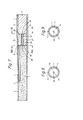
- Figure 1 is a cross-sectional side elevation of a cigarette incorporating the invention;
- Figure 2 is a cross-sectional end view on the line II-II of Figure 1;
- Figure 3 is a cross-sectional end view on the line III-III of Figure 1;
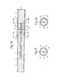
- Figure 4 is a cross-sectional side elevation of another construction;
- Figure 5 is a cross-sectional end view on the line V-V of Figure 4;
- Figure 6 is a cross-sectional end view on the line VI-VI of Figure 4;
- Figure 7 is a cross-sectional side elevation of another construction according to the invention;
- Figure 8 is a cross-sectional end view on the line VIII-VIII of Figure 7;
- Figure 9 is a cross-sectional end view on the line IX-IX of Figure 7;
- Figure 10 is a cross-sectional side elevation of another construction;
- Figure 11 is a cross-sectional end view on the line XI-XI of Figure 10;
- Figure 12 is a cross-sectional end view on the line XII-XII on Figure 10.
- In the constructions of the invention to be described the tobacco rod of a cigarette is provided with an axially aligned combustible tube which is shorter than the tobacco rod and is positioned with one end adjacent to a control element. This element is provided with a flow path or paths for the introduction of ambient diluting air through which, initially, the flow is restricted or completely arrested by a film of low melting point, impermeable material forming a seal across the potential pathways. This film, or a region of it, is situation in close proximity to the end of the tube in the tobacco rod. Air dilution of the smoke is introduced or increased during smoking when the burning zone of the tobacco rod reaches the tube and hot air and/or smoke passes along the tube, melts the low-melting film and, thus, opens up the ventilation flow path.
- In the construction shown in Figures 1, 2 and 3 a cigarette according to the invention comprises a
tobacco rod 1 wrapped incigarette paper 2 attached to a two part filter, indicated generally byreference numeral 3, by atipping paper 4. An axially alignedtube 5 is located within thetobacco rod 1 with oneend 6 adjacent to the twopart filter rod 3 and theother end 7 is situated within the tobacco column. Theend 7 may be either open or sealed. The length of thetube 5 is less than that of the tobacco rod, for example, between 10% and 90% and more preferably between 10% and 60% of the length of the tobacco rod. The diameter of the tube is between 0.2 mm and 4 mm, preferably between 0.5 mm and 2.5 mm and more preferably between 1.0 mm and 2.0 mm. This tube is constructed from a combustible material, for example paper, cardboard or reconstituted tobacco sheet having a permeability of less than 100 cm/min cbar, preferably of less than 50 cm/min cbar. - The two part filter rod comprises means for introducing a flow of ambient diluting air in the form of a
control element 8 and afilter element 9 made from conventional filter material. The two parts are held together by aplug wrap 10. - The
control element 8 is substantially cylindrical and has acentral smoke channel 11. The upstream end of the element is formed with anannular recess 12 so that thesmoke channel 11 is continued bywalls 13. Therecess 12 has one or more radially extendingholes 14 in the peripheral region which register with holes orporous regions 15 in thetipping paper 4 and plugwrap 10 to provide flow paths for ambient air to become entrained with the smoke when heated air and/or smoke exiting thetube 5 atend 6 melts a film oflow melting material 16 which extends over the face of theannular recess 12. As theupstream end 17 of thechannel 11 is open thechannel 11 provides a flow path for smoke throughout the smoking of the cigarette. When thelow melt material 16 melts however a second flow path for ambient diluting air is opened up which extends through theair holes 14 axially through theannular recess 12 into thetobacco rod 1 upstream of thecontrol element 8 and then into thecentral smoke passage 11. - Throughout the smoking of the cigarette, even when the ambient air ventilation flow paths have opened the smoke is filtered by the
filter element 9. - In this construction the
control element 9 may be constructed from any appropriate rigid material such as metal or carbon, but preferably a synthetic plastics material is employed, for example polyethylene, polypropylene, cellulose acetate or nylon. In the arrangement shown the body of the element is solid but, if desired it could be hollow provided the necessary flow paths are maintained discrete. - In the construction shown in Figures 4, 5 and 6 the same reference numerals are used to indicate similar parts as those shown in Figures 1, 2 and 3, the
control element 18 however has asmoke flow passage 19, theends air flow passages 22 are provided and an additionalsmoke flow passage 23 extends through the element. - The
tube 5 is co-axial with thetobacco rod 1 and thecigarette end 6 is aligned with thesmoke flow passage 19. - The
air flow passages 22 connect thepassage 19 to the curved surface of the element where they register with holes orporous regions 15 in the tippingpaper 4 to provide the air flow paths. - Although both ends of the
passage 19 are shown as being sealed, only theend 20 may be sealed if desired. - When the hot gases in the
tube 5 melt the sealing film, ventilation through thepassages 22 is provided. Two or moreadditional passages 23 may be provided to allow smoke passage through the control element into thefilter element 9 prior to the opening of thepassage 19. - Figures 7, 8 and 9 show another construction of control element and once again the same reference numerals are used to indicate similar parts as in the other figures. In this embodiment the
tube 5 is again adjacent the wall of thetobacco rod 1 but thecontrol element 25 comprises a plug offilter material 26 which is annular in cross-section and held in place on the outside by the porous orperforated plug wrap 10. Thefilter material 26 surrounds animpermeable tube 27 havingopen ends annular plug 26 adjacent thetobacco rod 1 is sealed, initially, by a film oflow melting material 30. Optionally the other end of the plug may be sealed by a film of the same material or byother means 31. Thetube 27 provides apassage 32 for smoke and maybe empty or may contain a filter material (not shown) similar to or different from theplug 26. Ventilation is achieved through perforations orporous regions 15 in thetipping paper 4 andplug wrap 10 and is introduced or increased when thefilm 30, andfilm 31, when provided, melts through contact with hot air and/or smoke drawn through thetube 5 in the tobacco rod. Thus once again a flow path for ambient ventilating air is provided, in this case into the control element itself and then into thefilter element 9. - Figures 10, 11 and 12 show another construction in which the same reference numerals are once again used to indicate similar parts to those shown in the other Figures. In this construction the
tube 5 is again positioned along the central axis of thetobacco rod 1 but thecontrol element 35 comprises an annular plug of filter material wrapped on the outside by the porous orperforated plug wrap 10. The annular plug of filter material surrounds animpermeable tube 36 one end of the tube being sealed initially by a film oflow melting material 37 and, optionally, the other end of thetube 36 may be sealed by afilm 38 of the same material or by other means. Thetube 36 can be empty or may contain afilter material 39 as shown in the drawing which is similar to or different from the filter material comprising the plug. One ormore air passages 40 are provided connecting thetube 36 to the curved surface of the plug and these register with holes orporous regions 15 in thetipping paper 4 and plugwrap 10. The plug of filter material provides the flow path for smoke and ambient air ventilation is introduced or increased when thefilm 37, and thefilm 38, when provided, melt through contact with hot air and/or smoke drawn through thetube 5 in thetobacco rod 1. - The
tube 32 shown in Figure 7 and thetube 36 shown in Figure 10 may be made from any suitable material such as polyethylene, polypropylene, cellulose acetate, nylon or other synthetic plastics material. The filter material used in the control elements shown in Figures 7 and 10 may be of any commonly used materials, for example cellulose acetate, polyethylene or polypropylene fibre tow or web, or paper. - The low melting material employed to form a film in all the embodiments described can have a melting point below 150° C and preferably below 1OO` C and more preferably below 70 C. Hot melt adhesives of melting point around 60 C have been found to be suitable. In all the arrangements described above the
additional filter element 9 is included but if desired this could be omitted so that the control element forms the mouthpiece of the cigarette. - An example of a cigarette made according to the invention is as follows :
- An axial central hole (1.0 mm diameter) and an annular recess (inner diameter 3.0 mm, outer diameter 6.0 mm) were cut into a nylon cylinder ( 8 mm diameter, 23.0 mm length). The axial hole extended the whole length of the cylinder whilst the recess was cut commencing at a flat face to a depth of 8.0 mm. Six ventilation holes (each 0.8 mm diameter) were drilled equidistant around the circumference of the cylinder through the outer wall of the recess at a distance of 7.0 mm from the face. A thin film of hot melt adhesive (melting point around 60 C) was applied to cover the annular opening of the recess.
- Cigarettes were constructed from the control element by attaching separately 64 mm tobacco rods, containing a cylindrical empty paper tube (42 mm long, 2.0 mm diameter), to the end with the hot melt adhesive and 20 mm cellulose acetate filters to the other end. The paper tube was located at the periphery of the tobacco rod with one end adjacent to the control element and the other end, which was sealed by crimping, at a
position 22 mm from the lit end. - The cigarettes were tested using a vacuum driven smoking machine set to take 35 ml square-wave puffs of
duration 2 seconds at a frequency of one puff per minute. The total flow from the cigarette and the flow of air into the filter rod through the six ventilation holes were measured using appropriate flow sensors linked to pressure transducers in order to determine the level of tip ventilation of the cigarette at each puff. - The results obtained for tests of four cigarettes constructed in this way were as follows :

Claims (17)
Applications Claiming Priority (2)
| Application Number | Priority Date | Filing Date | Title |
|---|---|---|---|
| GB909004140A GB9004140D0 (en) | 1990-02-23 | 1990-02-23 | Cigarette or cigar |
| GB9004140 | 1990-02-23 |
Publications (2)
| Publication Number | Publication Date |
|---|---|
| EP0443749A2 true EP0443749A2 (en) | 1991-08-28 |
| EP0443749A3 EP0443749A3 (en) | 1993-06-09 |
Family
ID=10671527
Family Applications (1)
| Application Number | Title | Priority Date | Filing Date |
|---|---|---|---|
| EP19910300968 Withdrawn EP0443749A3 (en) | 1990-02-23 | 1991-02-06 | Cigarette or cigar |
Country Status (3)
| Country | Link |
|---|---|
| EP (1) | EP0443749A3 (en) |
| GB (1) | GB9004140D0 (en) |
| IE (1) | IE910429A1 (en) |
Cited By (2)
| Publication number | Priority date | Publication date | Assignee | Title |
|---|---|---|---|---|
| GB2296853A (en) * | 1995-01-12 | 1996-07-17 | Chiu Christopher Chi Wah | Safety cigarette |
| WO2006100605A1 (en) * | 2005-03-21 | 2006-09-28 | Philip Morris Products S.A. | Smoking article comprising a segmented rod of smokable material |
Family Cites Families (7)
| Publication number | Priority date | Publication date | Assignee | Title |
|---|---|---|---|---|
| AU1008470A (en) * | 1969-01-14 | 1971-07-08 | Steigerwald Karlheinz | Method and device for smoking acord of smokable material |
| US3699972A (en) * | 1970-08-31 | 1972-10-24 | Brown & Williamson Tobacco Corp | Cigarette |
| GB1378145A (en) * | 1971-10-11 | 1974-12-18 | British American Tobacco Co | Smoking articles |
| US3774622A (en) * | 1971-11-16 | 1973-11-27 | K Steigerwald | Device,particularly a cigarette,for smoking a cord of smokable material |
| GB1400278A (en) * | 1972-06-06 | 1975-07-16 | British American Tobacco Co | Smoking articles |
| GB8518385D0 (en) * | 1985-07-20 | 1985-08-29 | British American Tobacco Co | Tobacco smoke filters |
| US4867182A (en) * | 1988-03-16 | 1989-09-19 | R. J. Reynolds Tobacco Company | Temperature/humidity controlled valve for a smoking article |
-
1990
- 1990-02-23 GB GB909004140A patent/GB9004140D0/en active Pending
-
1991
- 1991-02-06 EP EP19910300968 patent/EP0443749A3/en not_active Withdrawn
- 1991-02-08 IE IE042991A patent/IE910429A1/en unknown
Cited By (2)
| Publication number | Priority date | Publication date | Assignee | Title |
|---|---|---|---|---|
| GB2296853A (en) * | 1995-01-12 | 1996-07-17 | Chiu Christopher Chi Wah | Safety cigarette |
| WO2006100605A1 (en) * | 2005-03-21 | 2006-09-28 | Philip Morris Products S.A. | Smoking article comprising a segmented rod of smokable material |
Also Published As
| Publication number | Publication date |
|---|---|
| EP0443749A3 (en) | 1993-06-09 |
| GB9004140D0 (en) | 1990-04-18 |
| IE910429A1 (en) | 1991-08-28 |
Similar Documents
| Publication | Publication Date | Title |
|---|---|---|
| AU2007231147B2 (en) | Smoking article with a restrictor | |
| US5190060A (en) | Smokable article | |
| KR100390357B1 (en) | Filter for a cigarette and a filter-tipped cigarette | |
| US4582071A (en) | Tipping assembly for an elongate smoking article | |
| US3774622A (en) | Device,particularly a cigarette,for smoking a cord of smokable material | |
| US7987856B2 (en) | Smoking article with bypass channel | |
| JP2014532437A (en) | Smoking articles with movable vapor release elements | |
| MX2011004302A (en) | Smoking article filter. | |
| KR100390358B1 (en) | Filter for a cigarette and filter cigarette | |
| US4660579A (en) | Tobacco smoke filters | |
| US4986287A (en) | Coaxial cigarette | |
| FI70513B (en) | CIGARRETTFILTER | |
| FI89552C (en) | Coaxial filter cigarette | |
| IE52633B1 (en) | Tobacco product | |
| EP0443749A2 (en) | Cigarette or cigar | |
| US4557281A (en) | Filtered cigarette | |
| US4911684A (en) | Smoking article mouthpieces | |
| US4865055A (en) | Ventilated cigarette of uniform flavor | |
| US4693265A (en) | Cigarette filter having low visible staining | |
| FI80825B (en) | ROEKNINGSARTIKEL. | |
| CN113287780A (en) | Dual-purpose cigarette with large smoke quantity and using method and application thereof | |
| US4644963A (en) | Smoking articles | |
| CA1200732A (en) | Smoking article filters | |
| US4723561A (en) | Smoking articles | |
| US4700724A (en) | Smoking-articles mouthpieces-elements |
Legal Events
| Date | Code | Title | Description |
|---|---|---|---|
| PUAI | Public reference made under article 153(3) epc to a published international application that has entered the european phase |
Free format text: ORIGINAL CODE: 0009012 |
|
| AK | Designated contracting states |
Kind code of ref document: A2 Designated state(s): BE CH DE DK ES FR GB GR IT LI LU NL |
|
| PUAL | Search report despatched |
Free format text: ORIGINAL CODE: 0009013 |
|
| AK | Designated contracting states |
Kind code of ref document: A3 Designated state(s): BE CH DE DK ES FR GB GR IT LI LU NL |
|
| 17P | Request for examination filed |
Effective date: 19930728 |
|
| RAP1 | Party data changed (applicant data changed or rights of an application transferred) |
Owner name: ROTHMANS INTERNATIONAL SERVICES LIMITED |
|
| STAA | Information on the status of an ep patent application or granted ep patent |
Free format text: STATUS: THE APPLICATION HAS BEEN WITHDRAWN |
|
| 18W | Application withdrawn |
Withdrawal date: 19940201 |