EP0443672B1 - Asynchronous transfer mode system - Google Patents
Asynchronous transfer mode system Download PDFInfo
- Publication number
- EP0443672B1 EP0443672B1 EP91200318A EP91200318A EP0443672B1 EP 0443672 B1 EP0443672 B1 EP 0443672B1 EP 91200318 A EP91200318 A EP 91200318A EP 91200318 A EP91200318 A EP 91200318A EP 0443672 B1 EP0443672 B1 EP 0443672B1
- Authority
- EP
- European Patent Office
- Prior art keywords
- cells
- buffers
- multiplexer
- incoming
- control circuit
- Prior art date
- Legal status (The legal status is an assumption and is not a legal conclusion. Google has not performed a legal analysis and makes no representation as to the accuracy of the status listed.)
- Expired - Lifetime
Links
Images

Classifications
-
- H—ELECTRICITY
- H04—ELECTRIC COMMUNICATION TECHNIQUE
- H04L—TRANSMISSION OF DIGITAL INFORMATION, e.g. TELEGRAPHIC COMMUNICATION
- H04L12/00—Data switching networks
- H04L12/54—Store-and-forward switching systems
- H04L12/56—Packet switching systems
- H04L12/5601—Transfer mode dependent, e.g. ATM
-
- H—ELECTRICITY
- H04—ELECTRIC COMMUNICATION TECHNIQUE
- H04L—TRANSMISSION OF DIGITAL INFORMATION, e.g. TELEGRAPHIC COMMUNICATION
- H04L49/00—Packet switching elements
- H04L49/10—Packet switching elements characterised by the switching fabric construction
- H04L49/104—Asynchronous transfer mode [ATM] switching fabrics
- H04L49/105—ATM switching elements
- H04L49/106—ATM switching elements using space switching, e.g. crossbar or matrix
-
- H—ELECTRICITY
- H04—ELECTRIC COMMUNICATION TECHNIQUE
- H04L—TRANSMISSION OF DIGITAL INFORMATION, e.g. TELEGRAPHIC COMMUNICATION
- H04L12/00—Data switching networks
- H04L12/54—Store-and-forward switching systems
- H04L12/56—Packet switching systems
- H04L12/5601—Transfer mode dependent, e.g. ATM
- H04L2012/5672—Multiplexing, e.g. coding, scrambling
-
- H—ELECTRICITY
- H04—ELECTRIC COMMUNICATION TECHNIQUE
- H04L—TRANSMISSION OF DIGITAL INFORMATION, e.g. TELEGRAPHIC COMMUNICATION
- H04L12/00—Data switching networks
- H04L12/54—Store-and-forward switching systems
- H04L12/56—Packet switching systems
- H04L12/5601—Transfer mode dependent, e.g. ATM
- H04L2012/5678—Traffic aspects, e.g. arbitration, load balancing, smoothing, buffer management
- H04L2012/5681—Buffer or queue management
Definitions
- a fixed length block is a cell that has a predetermined number of bits in serial order.
- Each cell consists of a header and an information field.
- the path identification for the cell is accommodated in the header field.
- a route identifier is to be understood as a connection identifier or routing information.
- the connection identifier contains information about the destination or partial destination of the useful information.
- the routing information is added within the system in certain communication arrangements and contains an indication about a sub-destination within the transmission arrangement.
- the user information is housed in the information field.
- Cells are sequentially assigned to certain time periods (time frames). The duration of such a time period depends on the underlying clock frequency of the transmission component. If no useful information is available, empty cells are transmitted in such a time frame, i.e. Cells without useful information. Cells that contain useful information are referred to as useful cells.
- Such a switching matrix can be composed of several switching matrix blocks.
- Such a switching matrix block with several feeder and customer lines consists of several coupling elements.
- a coupling element contains several feeder lines and one customer line. In a coupling element, cells are fed from a feed line to a customer line. If cells arrive on several feeder lines during a time frame that want to access a customer line, special strategies for coupling are necessary.
- the Knockout Switch A simple, modular architecture for high-performance packet switching
- a coupling element which is connected to feeder lines.
- the coupling element contains a comparator (packet filter) assigned to each feeder line checks whether the path identification of the cell supplied matches the address of the output of the customer line going out from the coupling element. If there is no match, this is indicated by zeroing an added bit (activity bit). In the opposite case, this bit is set to one.
- the number of lines is reduced from N to L lines, so that when M feeder lines arrive, with L ⁇ M N N, cells with useful information, some cells are lost.
- a network shifter
- the cells arriving from the concentrator during a time frame and having an added bit with a one are read into the network.
- the cells are shifted in the network so that each output of the network emits cells evenly.
- the network outputs are each connected to a buffer.
- the reading process for a network with, for example, eight inputs and outputs assumes that five useful cells arrive in a first time frame and four useful cells arrive in a second time frame, as follows: First, the five useful cells are given to five outputs.
- the invention has for its object to provide a coupling element for an asynchronous time multiple transmission system, which is implemented with less circuitry.
- the multiplexer arrangement contains individual multiplexers for coupling the feeder lines to the buffers and a control circuit coupled to the comparators, that the control circuit, depending on the comparator signals supplied by the comparators, contains the individual multiplexers so controlled that they establish the coupling between the feeder lines each loaded with a cell and the buffers in a predetermined order, and that a multiplexer for coupling the buffers in cyclical order with the customer line is provided by control by means of the control circuit.
- the cells are first fed to a comparator, which checks whether the cells are to be transmitted to the customer line.
- a comparator which checks whether the cells are to be transmitted to the customer line.
- Cells intended for the customer line are fed to buffers for storage via a multiplexer arrangement.
- the multiplexer arrangement creates such connections between feeder lines and buffers that the cells approach the buffers in a certain order and evenly distributed. For example, if there are four buffers and feeder lines and a cell is present on a second and third feeder line in a first time frame, the cells can be read into a first and a second buffer, respectively.
- the cell on the second feed line can be placed in the first buffer and the cell on the third feed line in the second buffer.
- the cell on the first feeder line is read into a third buffer and the cell on the third feeder line into a fourth buffer.
- the cell on the fourth feeder line is fed back to the first buffer. Cyclic reading of the buffers is thus implemented.
- This type of control of the multiplexer arrangement means that the cells are evenly distributed over the buffers. Such a multiplexer arrangement is less complex than the implementation in the known coupling element. In addition, it is not necessary for the cells to be labeled with one bit each, which indicates whether the message should be delivered to the customer line. Only simple switching operations are carried out in the multiplexer arrangement. One cell is read from the buffers per time frame.
- the multiplexer connected to the outputs of the buffers is cyclically controlled. Empty cells, ie cells without a message, are not read into the buffers. The multiplexer arrangement is only released for the cells which are intended for the customer line. With this coupling element, the cells are switched through in accordance with their arrival in time, ie all cells of a time frame are placed on the customer line before the cells of the next time frame are led to a customer line.
- the multiplexer arrangement contains a control circuit which is connected to the comparators and which controls the individual multiplexers in such a way that they establish the coupling between the feeder lines, each loaded with a cell, and the buffers in a predetermined order.
- the comparator supplies the control arrangement with comparator signals, from which the control arrangement determines on which feeder line cells have been supplied. After evaluating the comparator signals, the control circuit releases the number of individual multiplexers corresponding to the number of cells arriving during a time frame.
- the multiplexer arrangement contains single multiplexers.
- the number of individual multiplexers is equal to the number of feeder lines.
- Each input of a single multiplexer is coupled to a different feeder line and the output of a single multiplexer is coupled to a buffer.
- the number of buffers is consequently also equal to the number of feeder lines. Provided that the buffers are not fully used, go to everyone during a time frame Feeder line cells arrive, no cells lost.
- the control circuit In order to be able to occupy the buffers in a predetermined order and uniformly, the control circuit must store which buffer was last used for reading in during a time frame. At the next time frame containing a cell, the control circuit releases the next buffer in the predetermined order for reading.
- control circuit has a decoder for evaluating the comparator signals and for supplying information to an evaluation circuit on which feeder line cells have arrived per time frame, and that the evaluation circuit for releasing the buffers is to be read into the cells , and for controlling the individual multiplexers is provided in such a way that the released buffers are coupled to the feeder lines loaded with cells.
- a decoder evaluates the feeder line on which cells have been supplied. The evaluation circuit then determines the number of buffers to be released and the individual multiplexers which establish the coupling between a feeder line and a buffer.
- the control circuit will also be used to control the multiplexer, the output of which is connected to the customer line.
- the buffers are connected to the customer line in cyclical order.
- a modulo-n counter is provided in the control circuit for controlling the multiplexer, where n is the number of buffers, and also a detection circuit to release the counter when the buffers are filled with cells. By changing the contents of the counter for each time frame, the counter creates a connection between a buffer and the customer line.
- the detection circuit may include a signal from the decoder, indicating how many cells have been delivered from the feeder lines in a time frame.
- the comparison in a comparator assigned to each feeder line can be carried out by the comparator checking whether the path identifier is assigned to a cell which is stored in a register connected to each feeder line. If the assignment is present, the comparator changes a comparator signal generated by it.
- the invention also relates to a coupling element of such an asynchronous time multiple transmission system.
- the principle of an asynchronous time multiple transmission system can be explained with the block diagram shown in FIG.
- the signals from a terminal e.g. Telephone, picture or sound signals are segmented in a packetizer and provided with a header field in which a path identifier is present.
- the route identification contains information about the destination of the signals.
- Such a terminal and the packetizer form a subscriber terminal 1.
- the data of such a terminal are transmitted within a time interval (time frame) in the form of cells. The duration of such a time frame depends on the underlying clock frequency of a transmission component.
- Such cells consist of the header field mentioned above and the useful information. If no data is to be transmitted within a time frame, an empty cell is formed, i.e. a cell in which it is indicated in the header that no further information follows. Such empty cells are used to synchronize the system.
- the cells that carry useful information are referred to as useful cells.
- the data are transmitted, for example, from 64 subscriber terminals 1 to a line trunk group 2 via 64 lines, each with a capacity of 150 Mbit / s.
- connection group 2 the data are summarized and transmitted over a smaller number of lines with a higher capacity. For example, this data can be carried over 16 lines with a capacity of 600 Mbit / s each.
- switching matrix 3 which consists of several switching matrix blocks and this consists of several switching elements composed, the data is conveyed by evaluating the route identification by placing it on a specific customer line.
- a coupling element consists of a circuit arrangement which is connected to several feeder lines and one customer line.
- the circuit arrangement or the coupling element can determine data which are to be forwarded to the customer line connected to the coupling element and create the necessary paths within the circuit arrangement for this.
- the switching matrix 3 is again connected to a line group 4 with several lines, for example 16 lines with a capacity of 600 Mbit / s.
- the line group 4 forwards the received data via lines to subscriber terminals 5. For example, 64 lines with a capacity of 150 Mbit / s each are provided.
- Such a system also transmits data from the subscriber terminal 5 to the subscriber terminal 1.
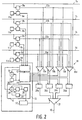
- FIG. 2 shows a coupling element which is part of a switching matrix.
- the coupling element is connected to four feeder lines 7a to d.
- a register 8a to d is connected to each feeder line 7a to d.
- the cells supplied on the feeder lines are stored in each register.
- a comparator 9a to d connected to each register compares the path identification of a cell stored in the registers 8a to d with the address of a customer line 10, which is stored in an address memory 11a to d.
- the route identification is understood here as the routing information which contains information about a partial destination within a transmission arrangement.
- the output of each comparator 9a to d is connected to a decoder 12, which is part of a control circuit 13.
- the decoder 12 which is used by the comparators 9a to d decoder supplied, supplies control signals to an evaluation circuit 14, an adder 15 and a detection circuit 16, which are all part of the control circuit 13.
- the control circuit 13 also contains a register 28, the input of which is connected to the output of the adder 15 and the output of which is connected to a further input of the adder 15 and the evaluation circuit 14.
- the detection circuit 16 releases a modulo-4 counter 17, which is also part of the control circuit 13.
- the control circuit 13 belongs to a multiplexer arrangement 18, which also includes four individual multiplexers 19a to d. Each individual multiplexer 19a to d contains four inputs which are each connected to an output of the registers 8a to d via lines 23a to d.
- the individual multiplexers 19a to d, the outputs of which are connected to the input of a buffer 20a to d, are controlled by the evaluation circuit 14.
- the buffers 20a to d are released by the evaluation circuit 14.
- the buffers 20a to d are FIFO's.
- the buffers should be dimensioned so that an overflow can practically not take place.
- the memory size of the FIFO's can be determined by traffic simulations of the coupling element.
- the lines leading away from the outputs of the buffers 20a to d go to the inputs of a multiplexer 21 which is controlled by the counter 17 and which alternately connects the various incoming lines to the customer line 10.
- FIG. 3 the four individual multiplexers 19a to d are shown as a block 22 for reasons of simplification.
- the four lines 23a to 23d leading from the registers 8a to d lead to this block 22.
- the four outputs of block 22 are coupled to buffers 20a to 20d.
- the four outputs of the buffers 20a to d are connected to the four inputs of the multiplexer 21, the output of which is connected to the customer line 10.
- Cell 1b is fed to buffer 20a by multiplexer arrangement 18 (or block 22).
- the individual multiplexer 19a connects the output of the register 8b to the input of the buffer 20a.
- the cell 1d is read into the buffer 20b.
- the individual multiplexer 19b connects the output of the register 8d to the input of the buffer 20b.
- a cell 2c arrive on line 23c and a cell 2d arrive on line 23d.
- Cell 2a is read into buffer 20c and cell 2c into buffer 20d.
- the cell 2d is again read into the buffer 20a.
- cell 1b was transferred from buffer 20a via multiplexer 21 to customer line 10.
- a cell 3b is to be transported on line 23b and a cell 3c is to be transported on line 23c during a third time frame.
- Cell 3b and cell 3c are read into buffers 20b and 20c.
- the cell 1d is meanwhile transferred from the buffer 20b to the customer line 10.
- cells 4a, 4b and 4c are to arrive on lines 23a, 23b and 23c.
- the cells 4a and 4c are read into the buffers 20d, 20a and 20b.
- cell 2a has been fed to customer line 10.
- the cells are distributed evenly across the buffers, i.e. the buffers are used optimally.
- the buffers are written in a predetermined order. That is, a cell supplied on line 23a is first read into buffer 20a and a cell on line 23b is read into buffer 20b. The order is defined so that the cells are first written into the buffers on the left in the drawing. The cell closest to the next time frame of line 23a in the drawing is thus written into the buffer which would have been the next buffer to be used in the last time frame.
- the control circuit used to control the individual multiplexers 19a to d, the buffers 20a to d and the multiplexer 21 13 decodes in the decoder 12, on which feeder line 7a to d cells have been received.
- the decoder 12 receives comparator signals from the comparators 9a to d.
- the comparator signal of a comparator can, for example, have a low signal state in the case of an empty cell or a cell which is intended for another customer line and a high signal state in the case of a cell which is intended for the customer line. It is assumed that the buffers 20a to d have not yet been occupied by any cell.
- the decoder 12 informs the evaluation circuit 14 on which feeder lines 7a to d cells have arrived.
- the single multiplexer 19a couples the line 23a to the buffer 20a, the single multiplexer 19b the line 23b to the buffer 20b, the single multiplexer 19c the line 23c to the buffer 20c and the single multiplexer 19d the line 23d to the buffer 20d. If, for example, there are no cells on the feeder lines 7a and 7c, the individual multiplexer 19a does not couple the line 23a to the buffer 20a, but rather the line 23b to the buffer 20a and the individual multiplexer 19b connects the line 23d to the buffer 20b. The single multiplexers 19c and d are not operated.
- the evaluation circuit 14 When the buffers 20a to d are read in, the evaluation circuit 14 still evaluates a signal which it receives from the register 28. Assume that register 28 has zero content. Decoder 12 provides the adder with the number of cells per time frame. In the first time frame, the content of the register 28 is added to the number of cells received in the adder 15 and these are stored in the register 28. At the next time frame, the evaluation circuit 14 learns from the content of the register 28 which buffer was last read in is. Since the adder 15 is a modulo-4 adder, if the addition result is larger than three, an overflow occurs. For example, three cells were read in during a first time frame and two cells were read in during a second subsequent time frame; the result of the addition is then one.
- the evaluation circuit learns from this number that the buffer 20a was last occupied in the last time frame, since the buffers 20a to 20d are occupied in a cyclical order. If no buffer is occupied, first the buffer 20a, then the buffer 20b, then the buffer 20c and finally the buffer 20d are actuated for storage.
- the detection circuit 16 and the modulo-4 counter 17 are provided to control the multiplexer 21.
- the detection circuit 16 contains an adder 24 which receives a signal from the decoder 12, a register 25, a comparison circuit 26 and a complement generator 27.
- the output of the adder 24 is connected to the input of the register 25 and its output to the input of the comparison circuit 26 and connected to another input of the adder 24.
- the output of the comparison circuit 26 is connected to the counter 17 and the input of the complement generator, whose output is connected to a further input of the adder 24.
- the decoder 12 supplies the adder 24 with the number of new cells to be stored in the buffers 20a to d.
- the adder adds the number of cells to be stored with the content of register 25.
- the result of the addition is then stored in register 25.
- the comparison circuit 26 it is checked whether the number in the register 25 is larger is as zero. If the number is greater than zero, an addition with the number "-1" also takes place in the next time frame by means of the complement generator 27.
- the counter 17 also receives the information from the comparison circuit 26 that a number greater than zero is also stored in the register 25. Then the counter 17 controls the multiplexer 21 so that it switches from one input to the next input.
- the buffer 20a is connected to the customer line 10 during a first time frame.
- the control circuit of the modulo 4 counter 17 creates a connection between the buffer 20b and the consumer line 10. In this way, the cells from the buffers 20a to 20d are cyclically output.
Description
Die Erfindung bezieht sich asynchrones Zeitvielfachübermittlungssystem mit einem Koppelelement,
- das zur Übertragung von bestimmten auf Zubringerleitungen eingetroffenen Zellen auf eine Abnehmerleitung vorgesehen ist,
- das mittels jeweils eines mit einer Zubringerleitung gekoppelten Vergleichers zur Prüfung vorgesehen ist, ob die in den Zellen enthaltene Wegekennung der Abnehmerleitung zugeordnet ist, und
- das eine Multiplexeranordnung zur Kopplung der Zubringerleitungen mit Puffern und zur gleichmäßigen Verteilung der für die Abnehmerleitung bestimmten, während eines Zeitrahmens eintreffenden Zellen auf die Puffer enthält.
- that is intended for the transfer of certain cells arriving on feeder lines to a customer line,
- that is provided by means of a comparator coupled to a feeder line for checking whether the route identification contained in the cells is assigned to the customer line, and
- which contains a multiplexer arrangement for coupling the feeder lines with buffers and for evenly distributing the cells destined for the customer line and arriving during a time frame onto the buffers.
Bei dem asynchronen Zeitvielfachübermittlungssystem werden Nutzinformationen, z.B. Fernsprech-, Bild- oder Tonsignale, in Blöcken fester Länge gesendet. Als ein Block fester Länge wird eine Zelle bezeichnet, die eine vorbestimmte Anzahl von Bits in serieller Reihenfolge aufweist. Jede Zelle besteht aus einem Kopf- und einem Informationsfeld. In dem Kopffeld ist u.a. die Wegekennung für die Zelle untergebracht. Unter einer Wegekennung ist eine Verbindungskennung oder eine Wegelenkungsinformation zu verstehen. In der Verbindungskennung ist die Angabe über das Ziel bzw. Teilziel der Nutzinformation enthalten. Die Wegelenkungsinformation wird innerhalb des Systems in bestimmten Übermittlungsanordnungen hinzugefügt und enthält eine Angabe über ein Teilziel innerhalb der Übermittlungsanordnung. Die Nutzinformation ist im Informationsfeld untergebracht.In the asynchronous time multiple transmission system, useful information, for example telephone, picture or sound signals, is sent in blocks of fixed length. A fixed length block is a cell that has a predetermined number of bits in serial order. Each cell consists of a header and an information field. Among other things, the path identification for the cell is accommodated in the header field. A route identifier is to be understood as a connection identifier or routing information. The connection identifier contains information about the destination or partial destination of the useful information. The routing information is added within the system in certain communication arrangements and contains an indication about a sub-destination within the transmission arrangement. The user information is housed in the information field.
Zellen sind aufeinanderfolgend bestimmten Zeitabschnitten (Zeitrahmen) zugeordnet. Die Dauer eines solche Zeitabschnittes hängt von der zugrundegelegten Taktfrequenz der Übermittlungskomponente ab. Falls keine Nutzinformation vorhanden ist, werden in einem solchen Zeitrahmen Leerzellen übertragen, d.h. Zellen ohne Nutzinformation. Zellen, die eine Nutzinformation beinhalten, werden als Nutzzellen bezeichnet.Cells are sequentially assigned to certain time periods (time frames). The duration of such a time period depends on the underlying clock frequency of the transmission component. If no useful information is available, empty cells are transmitted in such a time frame, i.e. Cells without useful information. Cells that contain useful information are referred to as useful cells.
Bei der Übertragung der Zellen zwischen Teilnehmern durchlaufen die Zellen Koppelfelder, in denen Wege durch Auswertung der Wegekennung hergestellt werden. Ein solches Koppelfeld kann sich dabei aus mehreren Koppelfeldblöcken zusammensetzen. Ein solcher Koppelfeldblock mit mehreren Zubringer- und Abnehmerleitungen besteht aus mehreren Koppelelementen. Ein Koppelelement enthält mehrere Zubringerleitungen und eine Abnehmerleitung. In einem Koppelelement werden dabei Zellen von einer Zubringerleitung auf eine Abnehmerleitung gegeben. Bei Eintreffen von Zellen auf mehreren Zubringerleitungen während eines Zeitrahmens, die auf eine Abnehmerleitung zugreifen wollen, sind besondere Strategien zur Kopplung notwendig.When the cells are transmitted between participants, the cells pass through coupling fields in which paths are created by evaluating the path identification. Such a switching matrix can be composed of several switching matrix blocks. Such a switching matrix block with several feeder and customer lines consists of several coupling elements. A coupling element contains several feeder lines and one customer line. In a coupling element, cells are fed from a feed line to a customer line. If cells arrive on several feeder lines during a time frame that want to access a customer line, special strategies for coupling are necessary.
Aus dem Aufsatz "The Knockout Switch: A simple, modular architecture for high-performance packet switching" von Y.S.Yeh, M.G. Hluchyj und A.S. Acampora, International Switching Symposium, 1987, Proceedings, Thursday, March 17, 1987, Volume 3 of 4, Session B 10.2 ist ein Koppelelement bekannt, das mit Zubringerleitungen verbunden ist. Das Koppelelement enthält einen jeder Zubringerleitung zugeordneten Vergleicher (packet-filter), der überprüft, ob die Wegekennung der gelieferten Zelle mit der Adresse des Ausgangs der vom Koppelelement abgehenden Abnehmerleitung übereinstimmt. Falls keine Übereinstimmung vorhanden ist, wird dies durch Nullsetzung eines hinzugefügten Bits (activity bit) gekennzeichnet. Im umgekehrten Fall wird dieses Bit gleich Eins gesetzt. In einem nachfolgenden Konzentrator (concentrator) wird die Anzahl der Leitungen von N auf L Leitungen verringert, so daß, wenn auf M Zubringerleitungen, wobei L < M ≤ N, Zellen mit einer Nutzinformation eintreffen, einige Zellen verlorengehen. In einem an den Konzentrator angeschlossenen Netzwerk (shifter) werden die vom Konzentrator während eines Zeitrahmens ankommenden Zellen, die ein hinzugefügtes Bit mit einer Eins aufweisen, in das Netzwerk eingelesen. In dem Netzwerk werden die Zellen so verschoben, daß jeder Ausgang des Netzwerkes gleichmäßig Zellen abgibt. Die Ausgänge des Netzwerkes sind jeweils mit einem Puffer verbunden. Der Auslesevorgang verläuft bei einem Netzwerk mit beispielsweise acht Ein- und Ausgängen unter der Voraussetzung, daß bei einem ersten Zeitrahmen fünf Nutzzellen und bei einem zweiten Zeitrahmen vier Nutzzellen eintreffen, folgendermaßen: Zuerst werden die fünf Nutzzellen auf fünf Ausgänge gegeben. Beim zweiten Zeitrahmen werden drei Zellen auf die restlichen drei beim vorherigen Zeitrahmen keine Zellen liefernden Ausgänge geleitet und die weitere Nutzzelle auf einen der anderen fünf Ausgänge. Die Auslesung wird also so gesteuert, daß eine gleichmäßige Belegung der Puffer erreicht wird. Aufwendig bei diesem Koppelelement ist, daß ein Bit (activity bit) zur Steuerung der Zellen hinzugefügt wird und daß alle Zellen mit einer Nachricht über den Konzentrator weitergegeben werden. Die Selektion der für die Abnehmerleitung bestimmten Zellen findet erst durch das Netzwerk statt. Außerdem können sich bei diesem Netzwerk, das ein Omega-Netzwerk ist, Blockierungen ergeben. Damit hierbei keine Zellen verloren gehen, sind im Netzwerk Speicher erforderlich, wodurch die Durchlaufzeit der Zellen im Netzwerk vergrößert wird.From the essay "The Knockout Switch: A simple, modular architecture for high-performance packet switching" by YSYeh, MG Hluchyj and AS Acampora, International Switching Symposium, 1987, Proceedings, Thursday, March 17, 1987,
Aus dem Dokument EP-A-0 256 702 ist das oben beschriebene System ebenfalls bekannt. Hier ist jedoch auch der Fall N = L beschrieben, bei dem keine Zellen durch einen Konzentrator verlorengehen.The system described above is also known from document EP-
Der Erfindung liegt die Aufgabe zugrunde, ein Koppelelement für ein asynchrones Zeitvielfachübermittlungssystem zu schaffen, das mit geringerem Schaltungsaufwand realisiert ist.The invention has for its object to provide a coupling element for an asynchronous time multiple transmission system, which is implemented with less circuitry.
Diese Aufgabe wird durch ein asynchrones Zeitvielfachübermittlungssystem der eingangs genannten Art dadurch gelöst, daß die Multiplexeranordnung Einzelmultiplexer zur Kopplung der Zubringerleitungen mit den Puffern und eine mit den Vergleichern gekoppelte Steuerschaltung enthält, daß die Steuerschaltung in Abhängigkeit von dem von den von den Vergleichern gelieferten Vergleichersignalen die Einzelmultiplexer so steuert, daß diese die Kopplung zwischen den mit jeweils einer Zelle beaufschlagten Zubringerleitungen und den Puffern in vorbestimmter Reihenfolge herstellen, und
daß durch Steuerung mittels der Steuerschaltung ein Multiplexer zur Kopplung der Puffer in zyklischer Reihenfolge mit der Abnehmerleitung vorgesehen ist.This object is achieved by an asynchronous time multiple transmission system of the type mentioned in the introduction in that the multiplexer arrangement contains individual multiplexers for coupling the feeder lines to the buffers and a control circuit coupled to the comparators, that the control circuit, depending on the comparator signals supplied by the comparators, contains the individual multiplexers so controlled that they establish the coupling between the feeder lines each loaded with a cell and the buffers in a predetermined order, and
that a multiplexer for coupling the buffers in cyclical order with the customer line is provided by control by means of the control circuit.
Bei diesem asynchronen Zeitvielfachübermittlungssystem, das ein Koppelelement enthält, werden die Zellen zuerst einem Vergleicher zugeführt, der überprüft, ob die Zellen auf die Abnehmerleitung zu übertragen sind. Hierbei werden nur Zellen mit einer Nutzinformation (Nutzzellen) auf die Abnehmerleitung übertragen. Zellen, die für die Abnehmerleitung bestimmt sind, werden über eine Multiplexeranordnung Puffern zur Speicherung zugeführt. Dabei stellt die Multiplexeranordnung solche Kopplungen zwischen Zubringerleitungen und Puffern her, daß die Zellen in einer bestimmten Reihenfolge und gleichmäßig verteilt den Puffern zugehen. Beispielsweise können, wenn vier Puffer und Zubringerleitungen vorhanden sind und in einem ersten Zeitrahmen jeweils eine Zelle auf einer zweiten und dritten Zubringerleitung vorhanden sind, die Zellen jeweils in einen ersten und zweiten Puffer eingelesen werden. Dabei kann die Zelle auf der zweiten Zubringerleitung in den ersten Puffer und die Zelle auf der dritten Zubringerleitung in den zweiten Puffer gegeben werden. Wenn beim nächsten Zeitrahmen jeweils eine Zelle auf der ersten, dritten und vierten Zubringerleitung geliefert wird, dann wird die Zelle auf der ersten Zubringerleitung in einen dritten Puffer und die Zelle auf der dritten Zubringerleitung in einen vierten Puffer eingelesen. Die Zelle auf der vierten Zubringerleitung wird wieder dem ersten Puffer zugeführt. Es wird somit eine zyklische Einlesung der Puffer realisiert. Durch diese Art der Steuerung der Multiplexeranordnung sind die Zellen gleichmäßig über die Puffer verteilt. Eine solche Multiplexeranordnung ist weniger aufwendig als die Realisierung im bekannten Koppelelement. Außerdem ist hierbei nicht erforderlich, daß die Zellen mit jeweils einem Bit zu kennzeichnen sind, das angibt, ob die Nachricht auf die Abnehmerleitung geliefert werden soll. Es werden nur einfache Schaltvorgänge in der Multiplexeranordnung vorgenommen. Aus den Puffern wird pro Zeitrahmen eine Zelle ausgelesen. Hierfür wird der mit den Ausgängen der Puffer verbundene Multiplexer zyklisch gesteuert. Leerzellen, d.h. Zellen ohne Nachricht, werden nicht in die Puffer eingelesen. Die Multiplexeranordnung wird nur für die Zellen freigegeben, die für die Abnehmerleitung bestimmt sind. Bei diesem Koppelelement werden die Zellen entsprechend ihrem zeitlichen Eintreffen durchgeschaltet, d.h. es werden alle Zellen eines Zeitrahmens auf die Abnehmerleitung gegeben, bevor die Zellen des nächsten Zeitrahmens auf eine Abnehmerleitung geführt werden.In this asynchronous time multiple transmission system, which contains a coupling element, the cells are first fed to a comparator, which checks whether the cells are to be transmitted to the customer line. Here are only transfer cells with user information (user cells) to the customer line. Cells intended for the customer line are fed to buffers for storage via a multiplexer arrangement. The multiplexer arrangement creates such connections between feeder lines and buffers that the cells approach the buffers in a certain order and evenly distributed. For example, if there are four buffers and feeder lines and a cell is present on a second and third feeder line in a first time frame, the cells can be read into a first and a second buffer, respectively. The cell on the second feed line can be placed in the first buffer and the cell on the third feed line in the second buffer. If at the next time frame a cell is delivered on the first, third and fourth feeder line, then the cell on the first feeder line is read into a third buffer and the cell on the third feeder line into a fourth buffer. The cell on the fourth feeder line is fed back to the first buffer. Cyclic reading of the buffers is thus implemented. This type of control of the multiplexer arrangement means that the cells are evenly distributed over the buffers. Such a multiplexer arrangement is less complex than the implementation in the known coupling element. In addition, it is not necessary for the cells to be labeled with one bit each, which indicates whether the message should be delivered to the customer line. Only simple switching operations are carried out in the multiplexer arrangement. One cell is read from the buffers per time frame. For this purpose, the multiplexer connected to the outputs of the buffers is cyclically controlled. Empty cells, ie cells without a message, are not read into the buffers. The multiplexer arrangement is only released for the cells which are intended for the customer line. With this coupling element, the cells are switched through in accordance with their arrival in time, ie all cells of a time frame are placed on the customer line before the cells of the next time frame are led to a customer line.
Die Multiplexeranordnung enthält eine Steuerschaltung, die mit den Vergleichern verbunden ist und welche die Einzelmultiplexer so steuert, daß diese die Kopplung zwischen den mit jeweils einer Zelle beaufschlagten Zubringerleitungen und den Puffern in vorbestimmter Reihenfolge herstellen. Der Vergleicher führt der Steueranordnung Vergleichersignale zu, aus denen die Steueranordnung ermittelt, auf welcher Zubringerleitung Zellen zugeführt worden sind. Nach der Auswertung der Vergleichersignale gibt die Steuerschaltung der Anzahl der während eines Zeitrahmens eingetroffenen Zellen entsprechende Anzahl von Einzelmultiplexern frei.The multiplexer arrangement contains a control circuit which is connected to the comparators and which controls the individual multiplexers in such a way that they establish the coupling between the feeder lines, each loaded with a cell, and the buffers in a predetermined order. The comparator supplies the control arrangement with comparator signals, from which the control arrangement determines on which feeder line cells have been supplied. After evaluating the comparator signals, the control circuit releases the number of individual multiplexers corresponding to the number of cells arriving during a time frame.
Wie oben erwähnt, enthält die Multiplexeranordnung Einzelmultiplexer. Die Anzahl der Einzelmultiplexer ist gleich der Anzahl der Zubringerleitungen. Jeder Eingang eines Einzelmultiplexers ist mit jeweils einer anderen Zubringerleitung und der Ausgang eines Einzelmultiplexers mit einem Puffer gekoppelt.As mentioned above, the multiplexer arrangement contains single multiplexers. The number of individual multiplexers is equal to the number of feeder lines. Each input of a single multiplexer is coupled to a different feeder line and the output of a single multiplexer is coupled to a buffer.
Da die Anzahl der Einzelmultiplexer gleich der Anzahl der Zubringerleitungen ist, ist folglich auch die Anzahl der Puffer gleich der Anzahl der Zubringerleitungen. Unter der Voraussetzung, daß die Puffer nicht vollständig belegt sind, gehen, wenn während eines Zeitrahmens auf jeder Zubringerleitung Zellen eintreffen, keine Zellen verloren.Since the number of individual multiplexers is equal to the number of feeder lines, the number of buffers is consequently also equal to the number of feeder lines. Provided that the buffers are not fully used, go to everyone during a time frame Feeder line cells arrive, no cells lost.
Um die Puffer in vorbestimmter Reihenfolge und gleichmäßig belegen zu können, muß die Steuerschaltung speichern, welcher Puffer während eines Zeitrahmens zuletzt zur Einlesung verwendet worden ist. Beim nächsten Zeitrahmen, der eine Zelle enthält, gibt die Steuerschaltung den nächsten Puffer der vorbestimmten Reihenfolge zur Einlesung frei.In order to be able to occupy the buffers in a predetermined order and uniformly, the control circuit must store which buffer was last used for reading in during a time frame. At the next time frame containing a cell, the control circuit releases the next buffer in the predetermined order for reading.
In einer Fortbildung der Erfindung ist vorgesehen, daß die Steuerschaltung einen Dekoder zur Auswertung der Vergleichersignale und zur Lieferung der Information zu einer Auswerteschaltung, auf welcher Zubringerleitung pro Zeitrahmen Zellen eingetroffen sind, und daß die Auswerteschaltung zur Freigabe der Puffer, in die Zellen eingelesen werden sollen, und zur Steuerung der Einzelmultiplexer in der Art vorgesehen ist, daß die freigegebenen Puffer mit den mit Zellen beaufschlagten Zubringerleitungen gekoppelt werden.In a further development of the invention it is provided that the control circuit has a decoder for evaluating the comparator signals and for supplying information to an evaluation circuit on which feeder line cells have arrived per time frame, and that the evaluation circuit for releasing the buffers is to be read into the cells , and for controlling the individual multiplexers is provided in such a way that the released buffers are coupled to the feeder lines loaded with cells.
In der Steuerschaltung wird also in einem Dekoder ausgewertet, auf welcher Zubringerleitung Zellen zugeführt worden sind. Die Auswerteschaltung ermittelt daraufhin die Anzahl der freizugebenden Puffer und die Einzelmultiplexer, welche die Kopplung zwischen einer Zubringerleitung und einem Puffer herstellen.In the control circuit, a decoder evaluates the feeder line on which cells have been supplied. The evaluation circuit then determines the number of buffers to be released and the individual multiplexers which establish the coupling between a feeder line and a buffer.
Die Steuerschaltung wird auch noch zur Steuerung des Multiplexers, dessen Ausgang mit der Abnehmerleitung verbunden ist, verwendet werden. Hierbei werden die Puffer in zyklischer Reihenfolge mit der Abnehmerleitung verbunden. Dazu ist in der Steuerschaltung zur Steuerung des Multiplexers ein modulo-n-Zähler vorgesehen, wobei n gleich der Anzahl der Puffer ist, und des weiteren eine Detektionsschaltung zur Freigabe des Zählers bei Belegung der Puffer mit Zellen. Durch Veränderung des Zählerinhaltes bei jedem Zeitrahmen schafft der Zähler eine Verbindung zwischen einem Puffer und der Abnehmerleitung. Die Detektionsschaltung kann ein Signal von dem Dekoder enthalten, wodurch mitgeteilt wird, wieviel Zellen bei einem Zeitrahmen von den Zubringerleitungen geliefert worden sind.The control circuit will also be used to control the multiplexer, the output of which is connected to the customer line. The buffers are connected to the customer line in cyclical order. For this purpose, a modulo-n counter is provided in the control circuit for controlling the multiplexer, where n is the number of buffers, and also a detection circuit to release the counter when the buffers are filled with cells. By changing the contents of the counter for each time frame, the counter creates a connection between a buffer and the customer line. The detection circuit may include a signal from the decoder, indicating how many cells have been delivered from the feeder lines in a time frame.
Der Vergleich in einem jeder Zubringerleitung zugeordneten Vergleicher kann durchgeführt werden, indem der Vergleicher prüft, ob die Wegekennung einer Zelle, die in einem mit jeder Zubringerleitung verbundenen Register gespeichert ist, zugeordnet ist. Falls die Zuordnung vorliegt, nimmt der Vergleicher eine Änderung eines von ihm erzeugten Vergleichersignals vor.The comparison in a comparator assigned to each feeder line can be carried out by the comparator checking whether the path identifier is assigned to a cell which is stored in a register connected to each feeder line. If the assignment is present, the comparator changes a comparator signal generated by it.
Die Erfindung bezieht sich auch auf ein Koppelelement eines solchen asynchronen Zeitvielfachübermittlungssystems.The invention also relates to a coupling element of such an asynchronous time multiple transmission system.
Ein Ausführungsbeispiel der Erfindung wird nachstehend anhand der Zeichnungen näher erläutert. Es zeigen:
- Fig. 1 ein Blockschaltbild eines asynchronen Zeitvielfachübermittlungssystems,
- Fig. 2 ein vereinfacht dargestelltes Koppelelement und Fig. 3 ein Beispiel für die Verarbeitung von auf der Zubringerleitung eintreffenden Zellen in dem Koppelelement nach Fig. 2.
- 1 is a block diagram of an asynchronous time multiple transmission system,
- Fig. 2 shows a simplified coupling element and 3 shows an example of the processing of cells arriving on the feeder line in the coupling element according to FIG. 2.
Mit dem in Fig. 1 dargestellten Blockschaltbild läßt sich das Prinzip eines asynchronen Zeitvielfachübermittlungssystems erläutern. Die Signale eines Endgerätes, z.B. Fernsprech-, Bild- oder Tonsignale, werden in einem Paketisierer segmentiert und mit einem Kopffeld, in dem eine Wegekennung vorhanden ist, versehen. Die Wegekennung beinhaltet die Angabe über das Ziel der Signale. Ein solches Endgerät und der Paketisierer bilden eine Teilnehmerendeinrichtung 1. Die Daten eines solchen Endgerätes werden dabei innerhalb eines Zeitintervalles (Zeitrahmen) in Form von Zellen übertragen. Die Dauer eines solchen Zeitrahmens hängt dabei von der zugrundegelegten Taktfrequenz einer Übermittlungskomponente ab. Solche Zellen bestehen aus dem schon oben erwähnten Kopffeld und der Nutzinformation. Sollen innerhalb eines Zeitrahmens keine Daten übertragen werden, so wird eine Leerzelle gebildet, d.h. eine Zelle, in der im Kopffeld angegeben ist, daß keine weitere Information folgt. Solche Leerzellen dienen zur Synchronisation des Systems. Die Zellen, die eine Nutzinformation tragen, werden als Nutzzellen bezeichnet.The principle of an asynchronous time multiple transmission system can be explained with the block diagram shown in FIG. The signals from a terminal, e.g. Telephone, picture or sound signals are segmented in a packetizer and provided with a header field in which a path identifier is present. The route identification contains information about the destination of the signals. Such a terminal and the packetizer form a subscriber terminal 1. The data of such a terminal are transmitted within a time interval (time frame) in the form of cells. The duration of such a time frame depends on the underlying clock frequency of a transmission component. Such cells consist of the header field mentioned above and the useful information. If no data is to be transmitted within a time frame, an empty cell is formed, i.e. a cell in which it is indicated in the header that no further information follows. Such empty cells are used to synchronize the system. The cells that carry useful information are referred to as useful cells.
In dem in Fig. 1 dargestellten Blockschaltbild werden die Daten z.B. von 64 Teilnehmerendeinrichtungen 1 über 64 Leitungen mit jeweils einer Kapazität von 150 Mbit/s zu einer Anschlußgruppe 2 übertragen. In der Anschlußgruppe 2 werden die Daten zusammengefaßt und über eine geringere Anzahl von Leitungen mit einer höheren Kapazität übertragen. Beispielsweise können diese Daten über 16 Leitungen mit einer Kapazität von jeweils 600 Mbit/s geführt werden. In einem nachfolgenden Koppelfeld 3, das sich aus mehreren Koppelfeldblöcken und diese aus mehreren Koppelelementen zusammensetzt, findet durch Auswertung der Wegekennung eine Vermittlung der Daten statt, indem sie auf eine bestimmte Abnehmerleitung gegeben werden. Ein Koppelelement besteht hierbei aus einer Schaltungsanordnung, die an mehrere Zubringerleitungen und eine Abnehmerleitung angeschlossen ist. Die Schaltungsanordnung bzw. das Koppelelement können Daten, die auf die mit dem Koppelelement verbundene Abnehmerleitung weitergeleitet werden sollen, ermitteln und die erforderlichen Wege innerhalb der Schaltungsanordnung dafür schaffen. Das Koppelfeld 3 ist wieder mit mehreren Leitungen, z.B. 16 Leitungen mit einer Kapazität von 600 Mbit/s mit einer Anschlußgruppe 4 verbunden. Die Anschlußgruppe 4 leitet die empfangenen Daten über Leitungen an Teilnehmerendeinrichtungen 5 weiter. Beispielsweise sind hierbei 64 Leitungen mit jeweils einer Kapazität von 150 Mbit/s vorgesehen. Ein solches System überträgt noch Daten von der Teilnehmerendeinrichtung 5 auf die Teilnehmerendeinrichtung 1.In the block diagram shown in FIG. 1, the data are transmitted, for example, from 64 subscriber terminals 1 to a
In Fig. 2 ist ein Koppelelement, das Teil eines Koppelfeldes ist, dargestellt. Das Koppelelement ist mit vier Zubringerleitungen 7a bis d verbunden. An jede Zubringerleitung 7a bis d ist jeweils ein Register 8a bis d angeschlossen. In jedem Register werden die auf den Zubringerleitungen zugeführten Zellen gespeichert. Ein mit jedem Register jeweils verbundener Vergleicher 9a bis d vergleicht die Wegekennung einer in den Registern 8a bis d gespeicherten Zelle mit der Adresse einer Abnehmerleitung 10, die in jeweils einem Adressenspeicher 11a bis d abgelegt ist. Unter der Wegekennung wird hierbei die Wegelenkungsinformation verstanden, die eine Angabe über ein Teilziel innerhalb einer Übermittlungsanordnung enthält. Der Ausgang jedes Vergleichers 9a bis d ist mit einem Dekoder 12 verbunden, der Teil einer Steuerschaltung 13 ist. Der Dekoder 12, der die von den Vergleichern 9a bis d gelieferten Vergleichersignale dekodiert, liefert Steuersignale einer Auswerteschaltung 14, einem Addierer 15 und einer Detektionsschaltung 16, die alle Teil der Steuerschaltung 13 sind. Die Steuerschaltung 13 enthält noch ein Register 28, dessen Eingang mit dem Ausgang des Addierers 15 verbunden ist und dessen Ausgang mit einem weiteren Eingang des Addierers 15 und der Auswerteschaltung 14 verbunden ist. Die Detektionsschaltung 16 gibt einen modulo-4-Zähler 17 frei, der ebenfalls Teil der Steuerschaltung 13 ist.2 shows a coupling element which is part of a switching matrix. The coupling element is connected to four feeder lines 7a to d. A
Die Steuerschaltung 13 gehört zu einer Multiplexeranordnung 18, die auch vier Einzelmultiplexer 19a bis d beinhaltet. Jeder Einzelmultiplexer 19a bis d enthält vier Eingänge, die an jeweils einem Ausgang der Register 8a bis d über Leitungen 23a bis d angeschlossen sind. Die Einzelmultiplexer 19a bis d, deren Ausgänge mit dem Eingang von jeweils einem Puffer 20a bis d verbunden sind, werden von der Auswerteschaltung 14 gesteuert. Die Puffer 20a bis d werden von der Auswerteschaltung 14 freigegeben. Die Puffer 20a bis d sind FIFO's. Die Puffer sollten so dimensioniert sein, daß ein Überlauf praktisch nicht stattfinden kann. Die Speichergröße der FIFO's läßt sich durch Verkehrssimulationen des Koppelelementes ermitteln. Die von den Ausgängen der Puffer 20a bis d wegführenden Leitungen gehen auf die Eingänge eines Multiplexers 21, der von dem Zähler 17 gesteuert wird und der die verschiedenen ankommenden Leitungen wechselweise mit der Abnehmerleitung 10 verbindet.The
Es sei erwähnt, daß die in Fig. 2 dargestellten Leitungen aus Gründen der Übersichtlichkeit in Form einer Leitung gezeichnet sind, obwohl sie teilweise aus mehreren parallelen Leitungen bestehen. Auch die für die Steuerung der einzelnen digitalen Schaltungselemente erforderlichen Taktleitungen und Taktgeneratoren sind nicht dargestellt.It should be mentioned that the lines shown in Fig. 2 are drawn in the form of a line for the sake of clarity, although they sometimes consist of several parallel lines. Also those necessary for the control of the individual digital circuit elements Clock lines and clock generators are not shown.
Die Funktionsweise des Koppelelementes nach Fig. 2 wird im folgenden mit Hilfe der Fig. 3 erläutert. In Fig. 3 sind aus Vereinfachungsgründen die vier Einzelmultiplexer 19a bis d als ein Block 22 dargestellt. Auf diesen Block 22 führen die vier von den Registern 8a bis d abgehenden Leitungen 23a bis 23d. Die vier Ausgänge des Blockes 22 sind mit den Puffern 20a bis 20d gekoppelt. Die vier Ausgänge der Puffer 20a bis d sind mit den vier Eingängen des Multiplexers 21 verbunden, dessen Ausgang an die Abnehmerleitung 10 angeschlossen ist.The mode of operation of the coupling element according to FIG. 2 is explained below with the aid of FIG. 3. In Fig. 3, the four
Von der Multiplexeranordnung 18 werden nur Zellen mit einer Nutzinformation (Nutzzellen) auf die Abnehmerleitung 10 gegeben. Eine Leerzelle wird folglich nicht auf die Abnehmerleitung 10 geführt. Ist in den Puffern keine Nutzzelle mehr vorhanden, die auf die Abnehmerleitung 10 gegeben werden kann, so erzeugt ein hier nicht näher dargestellter Leerzellengenerator Leerzellen, die auf die Abnehmerleitung 10 gegeben werden.From the
Zur Erläuterung sei angenommen, daß während eines ersten Zeitrahmens auf den Leitungen 23b und 23d Nutzzellen mit einer Nachricht eintreffen, die als Zellen 1b und 1d bezeichnet sind, wobei die Ziffer den jeweiligen Zeitrahmen und der Buchstabe die jeweilige Leitung bezeichnet, auf der die Zelle zugeführt wird. Die Zelle 1b wird von der Multiplexeranordnung 18 (oder Block 22) dem Puffer 20a zugeführt. Dazu verbindet der Einzelmultiplexer 19a den Ausgang des Registers 8b mit dem Eingang des Puffers 20a. Die Zelle 1d wird in den Puffer 20b eingelesen. Hierzu verbindet der Einzelmultiplexer 19b den Ausgang des Registers 8d mit dem Eingang des Puffers 20b. Es sei angenommen, daß während des nächsten Zeitrahmens auf der Leitung 23a eine Zelle 2a, auf der Leitung 23c eine Zelle 2c und auf der Leitung 23d eine Zelle 2d eintreffen. Die Zelle 2a wird in den Puffer 20c und die Zelle 2c in den Puffer 20d eingelesen. Die Zelle 2d wird wieder in den Puffer 20a eingelesen. Während des zweiten Zeitrahmens ist aus dem Puffer 20a die Zelle 1b über den Multiplexer 21 auf die Abnehmerleitung 10 gegeben worden. Beispielsweise sollen während eines dritten Zeitrahmens auf der Leitung 23b eine Zelle 3b und auf der Leitung 23c eine Zelle 3c transportiert werden. Die Zelle 3b und die Zelle 3c werden in die Puffer 20b und 20c eingelesen. Die Zelle 1d wird währenddessen aus dem Puffer 20b auf die Abnehmerleitung 10 gegeben. Während eines vierten Zeitrahmens sollen Zellen 4a, 4b und 4c auf den Leitungen 23a, 23b und 23c eintreffen. Die Zellen 4a und 4c werden in die Puffer 20d, 20a und 20b eingelesen. In dieser Zeit ist die Zelle 2a der Abnehmerleitung 10 zugeführt worden.For the sake of explanation, it is assumed that during a first time frame, payload cells arrive on
Durch diese Art der Belegung werden die Zellen auf die Puffer gleichmäßig verteilt, d.h. die Puffer werden optimal ausgenutzt. In dem in Fig. 3 dargestellten Beispiel werden die Puffer in einer vorbestimmten Reihenfolge eingeschrieben. Das bedeutet, daß eine Zelle, die auf der Leitung 23a zugeführt wird, zuerst in den Puffer 20a und eine Zelle auf der Leitung 23b in den Puffer 20b eingelesen wird. Die Reihenfolge ist also so festgelegt, daß die Zellen zuerst in die Puffer eingeschrieben werden, die in der Zeichnung links liegen. Die beim nächsten Zeitrahmen der Leitung 23a in der Zeichnung am nächsten liegende Zelle wird also in den Puffer eingeschrieben, das beim letzten Zeitrahmen der nächste zu belegende Puffer gewesen wäre.With this type of assignment, the cells are distributed evenly across the buffers, i.e. the buffers are used optimally. In the example shown in Fig. 3, the buffers are written in a predetermined order. That is, a cell supplied on
Die zur Steuerung der Einzelmultiplexer 19a bis d, der Puffer 20a bis d und des Multiplexers 21 verwendete Steuerschaltung 13 dekodiert im Dekoder 12, auf welcher Zubringerleitung 7a bis d Zellen empfangen worden sind. Dazu erhält der Dekoder 12 Vergleichersignale von den Vergleichern 9a bis d. Das Vergleichersignal eines Vergleichers kann z.B. bei einer Leerzelle oder einer Zelle, die für eine andere Abnehmerleitung bestimmt ist, einen niedrigen Signalzustand und bei einer Zelle, die für die Abnehmerleitung 10 bestimmt ist, einen hohen Signalzustand aufweisen. Es sei vorausgesetzt, daß die Puffer 20a bis d bisher mit keiner Zelle belegt sind. Der Dekoder 12 teilt der Auswerteschaltung 14 mit, auf welchen Zubringerleitungen 7a bis d Zellen angekommen sind. Es sei angenommen, daß auf jeder Zubringerleitung 7a bis d Zellen eingetroffen sind. Daraufhin koppelt der Einzelmultiplexer 19a die Leitung 23a mit dem Puffer 20a, der Einzelmultiplexer 19b die Leitung 23b mit dem Puffer 20b, der Einzelmultiplexer 19c die Leitung 23c mit dem Puffer 20c und der Einzelmultiplexer 19d die Leitung 23d mit dem Puffer 20d. Sollten beispielsweise auf den Zubringerleitungen 7a und 7c keine Zellen vorhanden sein, so koppelt der Einzelmultiplexer 19a nicht die Leitung 23a mit dem Puffer 20a sondern die Leitung 23b mit dem Puffer 20a und der Einzelmultiplexer 19b die Leitung 23d mit dem Puffer 20b. Die Einzelmultiplexer 19c und d werden nicht betätigt.The control circuit used to control the
Beim Einlesevorgang der Puffer 20a bis d wertet die Auswerteschaltung 14 noch ein Signal aus, das sie vom Register 28 erhält. Es sei vorausgesetzt, daß das Register 28 den Inhalt Null aufweist. Der Dekoder 12 liefert dem Addierer die Anzahl der Zellen pro Zeitrahmen. Beim ersten Zeitrahmen wird also im Addierer 15 der Inhalt des Registers 28 zur Anzahl der empfangenen Zellen addiert und diese im Register 28 abgespeichert. Beim nächsten Zeitrahmen erfährt die Auswerteschaltung 14 aus dem Inhalt des Registers 28, bei welchem Puffer zuletzt eingelesen worden ist. Da der Addierer 15 ein modulo-4-Addierer ist, entsteht, wenn das Additionsergebnis größer als drei ist, ein Überlauf. Beispielsweise sind während eines ersten Zeitrahmens drei Zellen eingelesen worden und während eines zweiten darauffolgenden Zeitrahmens zwei Zellen eingelesen worden; das Ergebnis der Addition ist dann Eins. Die Auswerteschaltung erfährt aus dieser Zahl, daß beim letzten Zeitrahmen zuletzt der Puffer 20a belegt worden ist, da die Puffer 20a bis 20d in zyklischer Reihenfolge belegt werden. Es werden also, wenn kein Puffer belegt ist, zuerst der Puffer 20a, dann der Puffer 20b, dann der Puffer 20c und letztlich der Puffer 20d zur Speicherung betätigt.When the buffers 20a to d are read in, the
Zur Steuerung des Multiplexers 21 ist die Detektionsschaltung 16 und der modulo-4-Zähler 17 vorgesehen. Die Detektionsschaltung 16 enthält einen Addierer 24, der ein Signal des Dekoders 12 erhält, ein Register 25, eine Vergleichsschaltung 26 und einen Komplementbilder 27. Der Ausgang des Addierers 24 ist mit dem Eingang des Registers 25 und dessen Ausgang mit dem Eingang der Vergleichsschaltung 26 und einem weiteren Eingang des Addierers 24 verbunden. Der Ausgang der Vergleichsschaltung 26 ist mit dem Zähler 17 und dem Eingang des Komplementbilders, der mit seinem Ausgang an einen weiteren Eingang des Addierers 24 angeschlossen ist, verbunden.The
Wenn in den Puffern 20a bis d keine Zelle vorhanden ist, so ist im Register 25 der Inhalt von Null gespeichert. Dem Addierer 24 wird vom Dekoder 12 die Zahl der neu in die Puffer 20a bis d zu speichernden Zellen zugeführt. Der Addierer addiert die Anzahl der zu speichernden Zellen mit dem Inhalt des Registers 25. Das Additionsergebnis wird dann im Register 25 abgespeichert. In der Vergleichsschaltung 26 wird geprüft, ob die Zahl im Register 25 größer als Null ist. Falls die Zahl größer als Null ist, findet beim nächsten Zeitrahmen mittels des Komplementbilders 27 auch eine Addition mit der Zahl "- 1" statt. Der Zähler 17 bekommt auch die Information von der Vergleichsschaltung 26, daß im Reqister 25 noch eine Zahl größer als Null gespeichert ist. Daraufhin steuert der Zähler 17 den Multiplexer 21 so an, daß dieser von einem Eingang auf den nächsten Eingang umschaltet. Beispielsweise ist während eines ersten Zeitrahmens der Puffer 20a mit der Abnehmerleitung 10 verbunden. Durch die Ansteuerschaltung des modulo-4-Zählers 17 wird eine Verbindung zwischen dem Puffer 20b und der Abnehmerleitung 10 geschaffen. Auf diese Art werden die Zellen aus den Puffern 20a bis 20d zyklisch ausgegeben.If there is no cell in buffers 20a to d, the content of zero is stored in
Bei dem aus Vereinfachungsgründen mit vier Zubringerleitungen dargestellten Koppelelement kann die Anzahl der Zubringerleitungen sehr viel größer sein.In the coupling element shown with four feeder lines for reasons of simplification, the number of feeder lines can be much larger.
Claims (7)
- Asynchronous time-division multiplex transmission system comprising an interconnection element,- which transmits certain cells that have come in via incoming trunks (7a to d) by an outgoing trunk (10),- which checks via a comparator (9a to d) coupled to an incoming trunk (7a to d) whether the routing identification code contained in the cells is assigned to the outgoing trunk (10), and- which includes a multiplexer arrangement (18) for coupling the incoming trunks (7a to d) to buffers (20a to d) and for uniformly distributing the cells arriving during a time frame and destined for the outgoing trunk (10), characterized in that the multiplexer arrangement (18) comprises individual multiplexers (19a to d) for coupling the incoming trunks (7a to d) to the buffers (20a to d) and a control circuit (13) coupled to the comparators (9a to d), in that the control circuit (13) controls the individual multiplexers (19a to d) in response to the comparing signals produced by the comparators (9a to d) in such a way that these multiplexers establish the coupling between the incoming trunks (7a to d) carrying each a cell and the buffers (20a to d) in a predetermined sequence, and in that, by controlling via the control circuit (13), a multiplexer (21) cyclically couples the buffers (20a to d) to the outgoing trunk (10).
- Asynchronous time-division multiplex transmission system as claimed in Claim 1, characterized in that the number of individual multiplexers (19a to d) is equal to the number of incoming trunks (7a to d), in that each input of an individual multiplexer (19a to d) is coupled to a different incoming trunk and in that the output of an individual multiplexer (19a to d) is coupled to a buffer (20a to d).
- Asynchronous time-division multiplex transmission system as claimed in Claim 2, characterized in that the control circuit (13) stores which buffer (20a to d) has been used last for writing during a time frame, and with the next time frame that contains a cell of payload information, releases the next buffer of the predetermined sequence to be written.
- Asynchronous time-division multiplex transmission system as claimed in Claim 3, characterized in that the control circuit (13) includes a decoder (12) for evaluating the comparing signals and for applying to an evaluation circuit (14) the information stating on which incoming trunk (7a to d) cells have arrived per time frame, and in that the evaluation circuit (14) releases the buffers (20a to d) in which the cells are to be written and controls the individual multiplexers (19a to d), so that the released buffers are coupled to the incoming trunks (7a to d) that carry cells.
- Asynchronous time-division multiplex transmission system as claimed in Claim 4, characterized in that the control circuit (13) for controlling the multiplexer (21) includes a modulo-n counter (17) where n equals the number of buffers (20a to d), and a detection circuit (16) for releasing the counter (17) when cells are written in the buffers (20a to d), and in that the counter (17), by changing its count with each time frame, creates a connection between a buffer (20a to d) and the outgoing trunk (10).
- Asynchronous time-division multiplex transmission system, characterized in that the comparator (9a to d) assigned to each incoming trunk (7a to d) checks whether the routing identification code of a cell, which code is stored in a register (8a to d) connected to each incoming trunk, is assigned to the outgoing trunk (10), and makes a change of a comparing signal produced thereby if the assignment exists.
- Interconnection element for an asynchronous time-division multiplex transmission system- which transmits certain cells that have come in via incoming trunks (7a to d) by an outgoing trunk (10),- which checks via a comparator (9a to d) coupled to an incoming trunk (7a to d) whether the routing identification code contained in the cells is assigned to the outgoing trunk (10), and- which includes a multiplexer arrangement (18) for coupling the incoming trunks (7a to d) to buffers (20a to d) and for uniformly distributing the cells arriving during a time frame and destined for the outgoing trunk (10), characterized in that the multiplexer arrangement (18) comprises individual multiplexers (19a to d) for coupling the incoming trunks (7a to d) to the buffers (20a to d) and a control circuit (13) coupled to the comparators (9a to d), in that the control circuit (13) controls the individual multiplexers (19a to d) in response to the comparing signals produced by the comparators (9a to d) in such a way that these multiplexers establish the coupling between the incoming trunks (7a to d) carrying each a cell and the buffers (20a to d) in a predetermined sequence, and in that, by controlling via the control circuit (13), a multiplexer (21) cyclically couples the buffers (20a to d) to the outgoing trunk (10).
Applications Claiming Priority (2)
| Application Number | Priority Date | Filing Date | Title |
|---|---|---|---|
| DE4004956 | 1990-02-19 | ||
| DE4004956A DE4004956A1 (en) | 1990-02-19 | 1990-02-19 | Interface circuit for async. time division multiplex system - uses comparators in conjunction with multiplexes and buffers |
Publications (3)
| Publication Number | Publication Date |
|---|---|
| EP0443672A2 EP0443672A2 (en) | 1991-08-28 |
| EP0443672A3 EP0443672A3 (en) | 1991-10-30 |
| EP0443672B1 true EP0443672B1 (en) | 1996-01-24 |
Family
ID=6400366
Family Applications (1)
| Application Number | Title | Priority Date | Filing Date |
|---|---|---|---|
| EP91200318A Expired - Lifetime EP0443672B1 (en) | 1990-02-19 | 1991-02-15 | Asynchronous transfer mode system |
Country Status (4)
| Country | Link |
|---|---|
| US (1) | US5228032A (en) |
| EP (1) | EP0443672B1 (en) |
| JP (1) | JP3204996B2 (en) |
| DE (2) | DE4004956A1 (en) |
Families Citing this family (7)
| Publication number | Priority date | Publication date | Assignee | Title |
|---|---|---|---|---|
| JP3051223B2 (en) * | 1991-10-02 | 2000-06-12 | 富士通株式会社 | Cell transmission circuit |
| DE69331187T2 (en) * | 1993-04-29 | 2002-06-06 | Alcatel Sa | Traffic generation means |
| US5541921A (en) * | 1994-12-06 | 1996-07-30 | National Semiconductor Corporation | Isochronous serial time division multiplexer |
| KR100318956B1 (en) * | 1995-12-26 | 2002-04-22 | 윤종용 | Apparatus and method for multiplexing cells in asynchronous transmission mode |
| US6683876B1 (en) * | 1996-09-23 | 2004-01-27 | Silicon Graphics, Inc. | Packet switched router architecture for providing multiple simultaneous communications |
| DE19722433A1 (en) * | 1997-05-28 | 1998-12-03 | Siemens Ag | Method and device for the transmission of a continuous data stream in packetized form |
| US8698044B2 (en) * | 2004-06-18 | 2014-04-15 | Textronics, Inc. | Textile structures for heating or warming |
Family Cites Families (9)
| Publication number | Priority date | Publication date | Assignee | Title |
|---|---|---|---|---|
| US3742145A (en) * | 1972-04-17 | 1973-06-26 | Itt | Asynchronous time division multiplexer and demultiplexer |
| US4597078A (en) * | 1983-10-19 | 1986-06-24 | Digital Equipment Corporation | Bridge circuit for interconnecting networks |
| US4630258A (en) * | 1984-10-18 | 1986-12-16 | Hughes Aircraft Company | Packet switched multiport memory NXM switch node and processing method |
| AR241357A1 (en) * | 1986-06-27 | 1992-05-29 | Siemens Ag | Method for controlling the information transmission of switched four-wire connections, especially semi-permanent switched connections in digital tdm exchanges |
| US4760570A (en) * | 1986-08-06 | 1988-07-26 | American Telephone & Telegraph Company, At&T Bell Laboratories | N-by-N "knockout" switch for a high-performance packet switching system |
| DE3732937A1 (en) * | 1987-09-30 | 1989-04-20 | Philips Patentverwaltung | CIRCUIT ARRANGEMENT FOR AVOIDING OVERLOAD IN A BROADBAND SWITCHING SYSTEM |
| FR2623953B1 (en) * | 1987-11-27 | 1992-11-20 | Cit Alcatel | MANAGEMENT UNIT FOR SWITCHING ELEMENT OF DATA TRANSMITTED BY ASYNCHRONOUS TIME MULTIPLEXING |
| DE68924191T2 (en) * | 1988-04-21 | 1996-05-09 | Nec Corp | Suitable packet switching for integrated circuit design. |
| FR2630876A1 (en) * | 1988-04-29 | 1989-11-03 | Trt Telecom Radio Electr | CIRCUIT ELEMENT CROSS POINT BETWEEN TWO OMNIBUS LINES |
-
1990
- 1990-02-19 DE DE4004956A patent/DE4004956A1/en not_active Withdrawn
-
1991
- 1991-02-15 US US07/656,898 patent/US5228032A/en not_active Expired - Fee Related
- 1991-02-15 EP EP91200318A patent/EP0443672B1/en not_active Expired - Lifetime
- 1991-02-15 DE DE59107292T patent/DE59107292D1/en not_active Expired - Fee Related
- 1991-02-19 JP JP2455991A patent/JP3204996B2/en not_active Expired - Fee Related
Also Published As
| Publication number | Publication date |
|---|---|
| US5228032A (en) | 1993-07-13 |
| JP3204996B2 (en) | 2001-09-04 |
| EP0443672A3 (en) | 1991-10-30 |
| DE59107292D1 (en) | 1996-03-07 |
| EP0443672A2 (en) | 1991-08-28 |
| DE4004956A1 (en) | 1991-08-22 |
| JPH04215347A (en) | 1992-08-06 |
Similar Documents
| Publication | Publication Date | Title |
|---|---|---|
| EP0320772B1 (en) | Method of hybrid packet switching and devices therefor | |
| DE69726995T2 (en) | Multicast routing in multilevel networks | |
| DE69737361T2 (en) | FAST COMMUNICATION DEVICE | |
| EP0584398B1 (en) | Method and circuit for transmitting information cells within an ATM network | |
| DE3752370T2 (en) | switching system | |
| DE60119866T2 (en) | Switching device and method with separate output buffers | |
| EP0384936B1 (en) | Method and circuit arrangement for forwarding information packets from incoming links via a packet-switching device | |
| DE2136361C3 (en) | Method for time division multiplex message transmission and switching device for a system for carrying out this method | |
| DE60031596T2 (en) | Time Division Multiple Access Switching System (TDM) with Very Wide Memory | |
| DE19531749A1 (en) | Traffic control method for packet-switching communication equipment e.g. ATM | |
| DE3214189C2 (en) | ||
| DE602005002452T2 (en) | Switching for integrated telecommunication networks | |
| DE2503111B2 (en) | METHOD AND CIRCUIT ARRANGEMENT FOR THE TIME MULTIPLEX TRANSMISSION OF USEFUL INFORMATION FROM INDEPENDENT SOURCES | |
| EP0412343A2 (en) | Switching network and module for an ATM-system | |
| EP0329005B1 (en) | Method for establishing virtual circuits via switches of a multistage switching arrangement | |
| EP0156339A2 (en) | Method and arrangement for establishing and operating a time division broadband communication in a TDM exchange | |
| DE19757965A1 (en) | Distributed buffer system for ATM switch | |
| DE19627842C2 (en) | Switching device | |
| DE3823878A1 (en) | COUPLING PANEL FOR A MEDIATION SYSTEM | |
| EP0006145A1 (en) | Circuit arrangement for a telecommunication exchange with microprocessors | |
| EP0443672B1 (en) | Asynchronous transfer mode system | |
| EP0428089B1 (en) | Subscriber node of a digital data transmission system | |
| DE69626679T2 (en) | SWITCHING DEVICE | |
| EP0322075B1 (en) | Switching network and controller for a switching system | |
| EP0442581B1 (en) | Asynchronous time division multiplex communication system |
Legal Events
| Date | Code | Title | Description |
|---|---|---|---|
| PUAI | Public reference made under article 153(3) epc to a published international application that has entered the european phase |
Free format text: ORIGINAL CODE: 0009012 |
|
| AK | Designated contracting states |
Kind code of ref document: A2 Designated state(s): DE FR GB IT SE |
|
| PUAL | Search report despatched |
Free format text: ORIGINAL CODE: 0009013 |
|
| AK | Designated contracting states |
Kind code of ref document: A3 Designated state(s): DE FR GB IT SE |
|
| 17P | Request for examination filed |
Effective date: 19920429 |
|
| 17Q | First examination report despatched |
Effective date: 19940217 |
|
| GRAA | (expected) grant |
Free format text: ORIGINAL CODE: 0009210 |
|
| AK | Designated contracting states |
Kind code of ref document: B1 Designated state(s): DE FR GB IT SE |
|
| REF | Corresponds to: |
Ref document number: 59107292 Country of ref document: DE Date of ref document: 19960307 |
|
| ITF | It: translation for a ep patent filed |
Owner name: ING. C. GREGORJ S.P.A. |
|
| ET | Fr: translation filed | ||
| GBT | Gb: translation of ep patent filed (gb section 77(6)(a)/1977) |
Effective date: 19960417 |
|
| PLBE | No opposition filed within time limit |
Free format text: ORIGINAL CODE: 0009261 |
|
| STAA | Information on the status of an ep patent application or granted ep patent |
Free format text: STATUS: NO OPPOSITION FILED WITHIN TIME LIMIT |
|
| 26N | No opposition filed | ||
| PGFP | Annual fee paid to national office [announced via postgrant information from national office to epo] |
Ref country code: SE Payment date: 19970225 Year of fee payment: 7 |
|
| PG25 | Lapsed in a contracting state [announced via postgrant information from national office to epo] |
Ref country code: SE Free format text: LAPSE BECAUSE OF NON-PAYMENT OF DUE FEES Effective date: 19980216 |
|
| REG | Reference to a national code |
Ref country code: FR Ref legal event code: CD |
|
| EUG | Se: european patent has lapsed |
Ref document number: 91200318.3 |
|
| PGFP | Annual fee paid to national office [announced via postgrant information from national office to epo] |
Ref country code: FR Payment date: 20010216 Year of fee payment: 11 |
|
| PGFP | Annual fee paid to national office [announced via postgrant information from national office to epo] |
Ref country code: GB Payment date: 20010227 Year of fee payment: 11 |
|
| PGFP | Annual fee paid to national office [announced via postgrant information from national office to epo] |
Ref country code: DE Payment date: 20010420 Year of fee payment: 11 |
|
| REG | Reference to a national code |
Ref country code: GB Ref legal event code: IF02 |
|
| PG25 | Lapsed in a contracting state [announced via postgrant information from national office to epo] |
Ref country code: GB Free format text: LAPSE BECAUSE OF NON-PAYMENT OF DUE FEES Effective date: 20020215 |
|
| PG25 | Lapsed in a contracting state [announced via postgrant information from national office to epo] |
Ref country code: DE Free format text: LAPSE BECAUSE OF NON-PAYMENT OF DUE FEES Effective date: 20020903 |
|
| GBPC | Gb: european patent ceased through non-payment of renewal fee |
Effective date: 20020215 |
|
| PG25 | Lapsed in a contracting state [announced via postgrant information from national office to epo] |
Ref country code: FR Free format text: LAPSE BECAUSE OF NON-PAYMENT OF DUE FEES Effective date: 20021031 |
|
| REG | Reference to a national code |
Ref country code: FR Ref legal event code: ST |
|
| PG25 | Lapsed in a contracting state [announced via postgrant information from national office to epo] |
Ref country code: IT Free format text: LAPSE BECAUSE OF NON-PAYMENT OF DUE FEES;WARNING: LAPSES OF ITALIAN PATENTS WITH EFFECTIVE DATE BEFORE 2007 MAY HAVE OCCURRED AT ANY TIME BEFORE 2007. THE CORRECT EFFECTIVE DATE MAY BE DIFFERENT FROM THE ONE RECORDED. Effective date: 20050215 |