EP0443638A1 - Transmission casing cover with tubular conduit cast in situ - Google Patents
Transmission casing cover with tubular conduit cast in situ Download PDFInfo
- Publication number
- EP0443638A1 EP0443638A1 EP91200025A EP91200025A EP0443638A1 EP 0443638 A1 EP0443638 A1 EP 0443638A1 EP 91200025 A EP91200025 A EP 91200025A EP 91200025 A EP91200025 A EP 91200025A EP 0443638 A1 EP0443638 A1 EP 0443638A1
- Authority
- EP
- European Patent Office
- Prior art keywords
- cover
- conduits
- body portion
- conduit
- manifold
- Prior art date
- Legal status (The legal status is an assumption and is not a legal conclusion. Google has not performed a legal analysis and makes no representation as to the accuracy of the status listed.)
- Granted
Links
Images


Classifications
-
- B—PERFORMING OPERATIONS; TRANSPORTING
- B22—CASTING; POWDER METALLURGY
- B22D—CASTING OF METALS; CASTING OF OTHER SUBSTANCES BY THE SAME PROCESSES OR DEVICES
- B22D19/00—Casting in, on, or around objects which form part of the product
- B22D19/0072—Casting in, on, or around objects which form part of the product for making objects with integrated channels
-
- F—MECHANICAL ENGINEERING; LIGHTING; HEATING; WEAPONS; BLASTING
- F16—ENGINEERING ELEMENTS AND UNITS; GENERAL MEASURES FOR PRODUCING AND MAINTAINING EFFECTIVE FUNCTIONING OF MACHINES OR INSTALLATIONS; THERMAL INSULATION IN GENERAL
- F16H—GEARING
- F16H57/00—General details of gearing
- F16H57/02—Gearboxes; Mounting gearing therein
- F16H57/031—Gearboxes; Mounting gearing therein characterised by covers or lids for gearboxes
-
- F—MECHANICAL ENGINEERING; LIGHTING; HEATING; WEAPONS; BLASTING
- F16—ENGINEERING ELEMENTS AND UNITS; GENERAL MEASURES FOR PRODUCING AND MAINTAINING EFFECTIVE FUNCTIONING OF MACHINES OR INSTALLATIONS; THERMAL INSULATION IN GENERAL
- F16H—GEARING
- F16H61/00—Control functions within control units of change-speed- or reversing-gearings for conveying rotary motion ; Control of exclusively fluid gearing, friction gearing, gearings with endless flexible members or other particular types of gearing
-
- F—MECHANICAL ENGINEERING; LIGHTING; HEATING; WEAPONS; BLASTING
- F16—ENGINEERING ELEMENTS AND UNITS; GENERAL MEASURES FOR PRODUCING AND MAINTAINING EFFECTIVE FUNCTIONING OF MACHINES OR INSTALLATIONS; THERMAL INSULATION IN GENERAL
- F16H—GEARING
- F16H57/00—General details of gearing
- F16H57/02—Gearboxes; Mounting gearing therein
- F16H2057/02017—Gearboxes; Mounting gearing therein characterised by special features related to the manufacturing of the gear case, e.g. special adaptations for casting
-
- F—MECHANICAL ENGINEERING; LIGHTING; HEATING; WEAPONS; BLASTING
- F16—ENGINEERING ELEMENTS AND UNITS; GENERAL MEASURES FOR PRODUCING AND MAINTAINING EFFECTIVE FUNCTIONING OF MACHINES OR INSTALLATIONS; THERMAL INSULATION IN GENERAL
- F16H—GEARING
- F16H57/00—General details of gearing
- F16H57/02—Gearboxes; Mounting gearing therein
- F16H2057/02039—Gearboxes for particular applications
- F16H2057/02043—Gearboxes for particular applications for vehicle transmissions
-
- F—MECHANICAL ENGINEERING; LIGHTING; HEATING; WEAPONS; BLASTING
- F16—ENGINEERING ELEMENTS AND UNITS; GENERAL MEASURES FOR PRODUCING AND MAINTAINING EFFECTIVE FUNCTIONING OF MACHINES OR INSTALLATIONS; THERMAL INSULATION IN GENERAL
- F16H—GEARING
- F16H61/00—Control functions within control units of change-speed- or reversing-gearings for conveying rotary motion ; Control of exclusively fluid gearing, friction gearing, gearings with endless flexible members or other particular types of gearing
- F16H2061/0046—Details of fluid supply channels, e.g. within shafts, for supplying friction devices or transmission actuators with control fluid
-
- Y—GENERAL TAGGING OF NEW TECHNOLOGICAL DEVELOPMENTS; GENERAL TAGGING OF CROSS-SECTIONAL TECHNOLOGIES SPANNING OVER SEVERAL SECTIONS OF THE IPC; TECHNICAL SUBJECTS COVERED BY FORMER USPC CROSS-REFERENCE ART COLLECTIONS [XRACs] AND DIGESTS
- Y10—TECHNICAL SUBJECTS COVERED BY FORMER USPC
- Y10T—TECHNICAL SUBJECTS COVERED BY FORMER US CLASSIFICATION
- Y10T74/00—Machine element or mechanism
- Y10T74/21—Elements
- Y10T74/2186—Gear casings
- Y10T74/2189—Cooling
Definitions
- the present invention relates generally to automatic transmissions for vehicles. More particularly, the present invention relates to the cover for at least one end of the casing in which the automatic transmission is housed. Specifically, the present invention relates not only to the configuration of the cover itself, but also to a unique method for making the cover.
- a cover is characterized by a manifold which incorporates a plurality of conduits; the manifold being encapsulated within the cover to communicate with, and be a functional part of, the hydraulic system utilized by the transmission mechanism.
- One particular prior art technique involves casting a transmission cover so that the end wall thereof is relatively thick.
- the relatively thick wall is then machined to incise a plurality of recessed pathways across the outer surface of the end wall.
- the end wall is then appropriately drilled to effect communication between the pathways and the remainder of the hydraulic system.
- a closure plate is secured over the recessed pathways to close each pathway from adjacent pathways as well as from atmosphere.
- a primary object of the present invention to provide an improved cover for at least one end of a transmission casing, the cover incorporating conduits therethrough which possess leak-proof integrity, even when connected to a source of hydraulic fluid under relatively high pressure.
- a cover in accordance with the present invention is characterised by the features specified in the characterising portion of Claim 1.
- the present invention is directed to the configuration of, and a method by which to make, a cover for at least one end of a transmission casing.
- the cover may incorporate a plurality of metallic conduits.
- the conduits which are preferably tubular, are shaped to a predetermined configuration and thereafter cast in situ within the body portion of the cover so that the ends of each conduit may communicate directly with the hydraulic system serving the transmission mechanism, irrespective of whether the hydraulic system utilizes discrete conduits interiorly of the casing; bores through the shafts of the transmission mechanism; or, passageways formed within the transmission casing.
- a method embodying the concepts of the present invention to fabricate a cover for a transmission casing utilizes several distinctly unique steps.
- a plurality of individual conduits are formed into predetermined configurations so that each conduit will be capable of communication with desired portions of the hydraulic system utilized by the transmission mechanism that is housed within the casing with which the cover is employed.
- a selected plurality of conduits, each having its own predetermined configuration, are conjoined into a unitary manifold. The manifold is accurately positioned within a mould, and molten metal is admitted into the mould to cast the manifold in situ within the body portion of the resulting cover.
- FIG. 10 One representative form of cover, the configuration of which embodies, and which is made in accordance with a method embodying, the concepts of the present invention is designated generally by the numeral 10 on the accompanying drawings and may be employed as the cap for one end of a casing within which a transmission mechanism is housed.
- Figures 1-3 illustrate elevational, top, and bottom views, respectively, of the cover 10.
- the body portion 12 of the cover 10 may be die-cast to make provision for a plurality of mounting bores 14 located at spaced intervals along the peripheral edge 16 of the body portion 12.
- the cover 10 may be bolted to the casing of a vehicular transmission (not shown) through the mounting bores 14.
- cover 10 may be made in a variety of configurations other than the one illustrated in the drawings.
- the specific configuration will depend primarily upon the number and orientation of conduits which may be required to pass through the cover 10.
- the number, and orientation, of conduits passing through the cover 10 will depend upon the number and positions of the passageways within the transmission casing to which the cover 10 is bolted as well as the number and position of independent passages interiorly of the transmission casing and the number and location of bores through the shafts within the transmission mechanism itself.
- the particular cover 10 depicted in the drawings is designed to pass hydraulic fluid pressure through five conduits incorporated within the body portion 12 of the cover 10, and these conduits communicate with five inlet ports and five outlet ports.
- the pathways of the five passages defined by the five conduits incorporated within the body portion 12 of the cover 10 may, of necessity, be somewhat contorted, and the passageways provided by the representative five conduits which extend through the body portion 12 of the cover 10 depicted are schematically traced by the chain lines in Figure 1, and they are designated generally by the numerals 20, 22, 24, 26 and 28, respectively.
- the five conduits which provide the passageways 20, 22, 24, 26 and 28, respectively are identified by the letters A, B, C, D, and E, and the ports through which each conduit opens are designated by the subscript numerals "1" and "2" applied to the letter designation for the conduit which terminates at the ports so designated.
- one end of the conduit A communicates through port A1
- the other end of conduit A communicates through port A2.
- one end of each of the conduits B through E communicates through ports B1, C1, D1 and E1 and the opposite end of each of those conduits communicates through ports B2, C2, D2 and E2.
- each conduit A through E has opposite ends which terminate at ports through which the respective passageways 20, 22, 24, 26 and 28 communicate.
- the ports are designated by the subscript numerals "1" and "2" applied to the letter designation of the conduit which communicates through that port.
- the conduits A through E may be individual, metallic tubes which are cast in situ within the metallic body portion 12 of the cover 10. While the exact pathway followed by each tubular conduit within the body portion 12 of the cover 10 may be arbitrary, the location of the ports through which the two opposite ends of each conduit communicate are fixed.
- the ports will, for example, be required to align with selected independent conduits interiorly of the casing; selected passageways within the transmission housing; or, selected bores axially within the shafts of the transmission mechanism.
- the tubular conduits A through E illustrated in Figure 4 have each been formed, or bent, to a predetermined configuration.
- each conduit it is provided with at least one limited linear span 30, 32, 34, 36 and 38, respectively, and the axes of the five linear spans are parallel so that the adjacent conduits may be easily conjoined to form a single, unitary manifold indicated generally by the reference numeral 40.
- the adjacent conduits may be conjoined by various means including welding, brazing or the like, and the joinder of the separate conduits into the unitary manifold 40 is indicated in Figure 4, as at 42.
- each conduit A through E is positioned in the mould, and thus within the body portion 12, as cast.
- the opposite ends of each conduit A through E terminates in a selvage portion 44 which extends beyond the envelope that delineates the confines of the body portion 12.
- each selvage portion 44 is preferably crimped closed, as at 46.
- the selvage portions 44 extending outwardly of the envelope formed by the body portion 12 are cut off at the interior surface 48 on the body portion 12 of the cover 10.
- the selvage portion 44 at the opposite ends of conduit A are removed -- the portion having been removed being depicted in chain line. The removal of the selvage portions 44 opens each conduit to permit unobstructed access to the interior passageway therethrough. The removal of the selvage 44 from each end of conduit A thus accesses passageway 20.
- an end cutting tool may be employed to complete the conduit-to-body portion interface at the interior surface 48 to form the ports designated by the subscripts "1 and "2" in the drawings.
- the end cutting tool will have been applied to form the ports B1 and B2 through which the passageway 22 within conduit B communicates.
- the body portion 12 of the cover 10 may be cast from aluminium, and the tubes A through E may be steel. It has been found that steel tubes with crimped, or swaged, ends are particularly successful not only to preclude the conduit from collapsing but also to preclude metal from intruding into the hollow interior of the conduit during the casting operation.
- aluminium conduits will work, an aluminium conduit requires greater wall thickness than comparable steel conduits in order to provide the strength necessary to withstand the pressures that may be applied by the molten metal during admission thereof into the mould. It must be appreciated that the increased wall thickness required for aluminium tubing may prevent the use of aluminium tubing in the limited space available in the environment of a vehicle transmission.
- a plurality of tubular conduits A through E are cut to length.
- the cut conduits A through E are formed, or bent, in a fixture so that each conduit satisfies the predetermined configuration for that conduit. Either before or after the conduits are bent, the two ends of each conduit are closed. Typically, the ends are spun, or swedged, to provide an air-tight closure 46 at the end of each selvage portion 44 located at the opposite ends of each conduit.
- a selected plurality of conduits A through E each having been bent to its uniquely predetermined configuration, are properly disposed and conjoined into a unitary manifold 40.
- each conduit may preferably be supplied with a linear portion. The linear portion of successive conduits may be disposed in contiguous juxtaposition and then conjoined.
- the conduits A through E are conjoined by being brazed or welded together, as appropriate for the particular material from which the conduits are made.
- An appropriate mould, or die, is provided within which the body portion 12 of the cover 10 can be cast.
- the interior surface of the mould is preferably coated with a releasing agent, and the manifold 40 is positioned within that mould.
- the selvage portions 44 of the several conduits A through E forming the manifold 40 are insertably received within a plurality of holes provided in, or through, the mould, and several gage points, or benchmarks, may be employed to assure that the manifold 40 is properly, and accurately, oriented within the mould. The mould is then closed and locked.
- Molten metal is admitted into the closed mould to form the body portion 12 of the cover 10 and to encapsulate the manifold in situ within the body portion 12.
- a die-casting technique is preferably employed to cast the body portion 12 of the cover 10 with the manifold 40 encapsulated therein.
- the mould is opened to remove the casting. The runner system, the flash and any other excess metal is then removed to leave only the body portion 12 of the cover 10 with the manifold 40 encapsulated therein.
- the selvage portion 44 is then removed from the terminal end portion of each conduit, and the ports are formed by using an end cutting tool to recess the end of each conduit A through E below the level of the interior surface 48 of the cover 10. Thereafter, any remaining machine operations, such as finishing the mounting bores and performing any other desired, or required, non-conduit related steps, may be performed to complete the cover.
- the present invention not only teaches a method for making a cover for the end of a transmission casing whereby the passages provided by the conduits encapsulated within the body portion of the cover are imbued with integrity from each other and from the atmosphere but also that the other objects of the invention can likewise be accomplished.
Abstract
Description
- The present invention relates generally to automatic transmissions for vehicles. More particularly, the present invention relates to the cover for at least one end of the casing in which the automatic transmission is housed. Specifically, the present invention relates not only to the configuration of the cover itself, but also to a unique method for making the cover. Such a cover is characterized by a manifold which incorporates a plurality of conduits; the manifold being encapsulated within the cover to communicate with, and be a functional part of, the hydraulic system utilized by the transmission mechanism.
- The advent of smaller automobiles has also encouraged the production of smaller, more compact engines and transmissions for such vehicles. In this regard efforts have been made to decrease the size of transmissions even further. Because the torque transferring devices -- that is, the brakes and clutches -- within the mechanism of a vehicular transmission are typically operated by hydraulic pressure, one effort to reduce the size of the transmission has resulted in the utilization of bores through the various shafts within the transmission, the bores serving as passageways in the hydraulic system by which pressurized fluid is directed to, and exhausted from, the torque transfer devices. Concomitant efforts have also been directed to the provision of passageways within the casing that houses the transmission mechanisms -- such passageways in the casing also being incorporated to convey pressurized fluid utilized by the hydraulic system of the transmission. In the continuing effort to decrease the size of the transmission, the cover for at least one end of the casing in which the transmission is housed has also been designed in various configurations to provide passageways therein which are included within the hydraulic system serving the transmission.
- One particular prior art technique involves casting a transmission cover so that the end wall thereof is relatively thick. The relatively thick wall is then machined to incise a plurality of recessed pathways across the outer surface of the end wall. The end wall is then appropriately drilled to effect communication between the pathways and the remainder of the hydraulic system. A closure plate is secured over the recessed pathways to close each pathway from adjacent pathways as well as from atmosphere. This prior art technique has been widely adopted, but it does have some drawbacks which include: (a) an increased cost for the material used to form the thicker-than-normal end wall in the cover; (b) an increased cost for machining the recessed pathways and for precisely, and accurately, drilling connecting bores from the pathways through the end wall to communicate with appropriate portions of the hydraulic system interiorly of, or within, the casing; (c) the need to provide a closure plate to cover the recessed pathways; and, (d) the need to employ seals between adjacent pathways, as well as between the pathways and atmosphere, to reduce not only the undesirable cross-communication between adjacent pathways but also the undesirable loss of hydraulic fluid to atmosphere.
- Closed passageways have also been provided in covers for transmission casings by the use of an expendable core when casting the cover. This approach, however, has also proven to be disadvantageous, particularly in view of the increased unit cost resulting from the additional steps required to make, and remove, the expendable core.
- It is, therefore, a primary object of the present invention to provide an improved cover for at least one end of a transmission casing, the cover incorporating conduits therethrough which possess leak-proof integrity, even when connected to a source of hydraulic fluid under relatively high pressure.
- To this end, a cover in accordance with the present invention is characterised by the features specified in the characterising portion of Claim 1.
- It is another object of the present invention to provide a cover, as above, for a transmission casing, the configuration of the cover obviating the need to provide separate means for sealing the conduits therethrough from each other, or from atmosphere.
- It is a further object of the present invention to provide a method by which to make an improved cover, as above, for a transmission casing, the improved cover requiring fewer machining operations and being, therefore, less labour intensive and less costly to manufacture.
- To this end, a method in accordance with the present invention is characterised by the features specified in Claim 5.
- In general, the present invention is directed to the configuration of, and a method by which to make, a cover for at least one end of a transmission casing. The cover may incorporate a plurality of metallic conduits. Specifically, the conduits, which are preferably tubular, are shaped to a predetermined configuration and thereafter cast in situ within the body portion of the cover so that the ends of each conduit may communicate directly with the hydraulic system serving the transmission mechanism, irrespective of whether the hydraulic system utilizes discrete conduits interiorly of the casing; bores through the shafts of the transmission mechanism; or, passageways formed within the transmission casing.
- As will be hereinafter more fully explained, a method embodying the concepts of the present invention to fabricate a cover for a transmission casing utilizes several distinctly unique steps. In that regard, a plurality of individual conduits are formed into predetermined configurations so that each conduit will be capable of communication with desired portions of the hydraulic system utilized by the transmission mechanism that is housed within the casing with which the cover is employed. A selected plurality of conduits, each having its own predetermined configuration, are conjoined into a unitary manifold. The manifold is accurately positioned within a mould, and molten metal is admitted into the mould to cast the manifold in situ within the body portion of the resulting cover.
- The present invention will now be described, by way of example, with reference to the accompanying drawings, in which:-
- Figure 1 is an elevational view of a cover for a transmission casing with the passages provided by the conduits, each following its own pathway through the cover, being schematically indicated generally in chain line, the cover having been made in accordance with the method of the present invention;
- Figure 2 is a top view of the cover depicted in Figure 1;
- Figure 3 is a bottom view taken substantially along line 3-3 of Figure 1 to depict the interior surface of the cover;
- Figure 4 is a bottom view of a plurality of individual conduits which have been shaped to a predetermined configuration and conjoined as a manifold in that predetermined disposition in which they are oriented in the exemplary cover depicted in Figures 1-3;
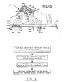
- Figure 5 is an elevational view, similar to Figure 1 and partially broken away, to show the manifold cast in situ and as it appears prior to the final machining of the cover; and
- Figure 6 is a flow chart designating the fundamental steps of a method embodying the steps of the present invention to make a cover as shown in Figures 1-3 and 5 for at least one end of a transmission casing.
- One representative form of cover, the configuration of which embodies, and which is made in accordance with a method embodying, the concepts of the present invention is designated generally by the
numeral 10 on the accompanying drawings and may be employed as the cap for one end of a casing within which a transmission mechanism is housed. Figures 1-3 illustrate elevational, top, and bottom views, respectively, of thecover 10. Thebody portion 12 of thecover 10 may be die-cast to make provision for a plurality ofmounting bores 14 located at spaced intervals along theperipheral edge 16 of thebody portion 12. Thecover 10 may be bolted to the casing of a vehicular transmission (not shown) through themounting bores 14. - It should be understood that the
cover 10 may be made in a variety of configurations other than the one illustrated in the drawings. The specific configuration, of course, will depend primarily upon the number and orientation of conduits which may be required to pass through thecover 10. The number, and orientation, of conduits passing through thecover 10 will depend upon the number and positions of the passageways within the transmission casing to which thecover 10 is bolted as well as the number and position of independent passages interiorly of the transmission casing and the number and location of bores through the shafts within the transmission mechanism itself. In any event, theparticular cover 10 depicted in the drawings is designed to pass hydraulic fluid pressure through five conduits incorporated within thebody portion 12 of thecover 10, and these conduits communicate with five inlet ports and five outlet ports. The pathways of the five passages defined by the five conduits incorporated within thebody portion 12 of thecover 10 may, of necessity, be somewhat contorted, and the passageways provided by the representative five conduits which extend through thebody portion 12 of thecover 10 depicted are schematically traced by the chain lines in Figure 1, and they are designated generally by thenumerals - More particularly, and with specific reference to Figures 2 and 3, the five conduits which provide the
passageways respective passageways - Referring to Figure 4 of the drawings, the conduits A through E may be individual, metallic tubes which are cast in situ within the
metallic body portion 12 of thecover 10. While the exact pathway followed by each tubular conduit within thebody portion 12 of thecover 10 may be arbitrary, the location of the ports through which the two opposite ends of each conduit communicate are fixed. The ports will, for example, be required to align with selected independent conduits interiorly of the casing; selected passageways within the transmission housing; or, selected bores axially within the shafts of the transmission mechanism. - The tubular conduits A through E illustrated in Figure 4 have each been formed, or bent, to a predetermined configuration. In so forming each conduit it is provided with at least one limited
linear span reference numeral 40. The adjacent conduits may be conjoined by various means including welding, brazing or the like, and the joinder of the separate conduits into theunitary manifold 40 is indicated in Figure 4, as at 42. - Conjoining the five, individual metal conduits A through E into a single,
unitary manifold 40 greatly facilitates mounting of the conduits within the mould prior to casting thebody portion 12 of thecover 10. Referring to Figure 5 of the drawings, themanifold 40 is represented in the disposition in which it is positioned in the mould, and thus within thebody portion 12, as cast. As clearly illustrated, the opposite ends of each conduit A through E terminates in aselvage portion 44 which extends beyond the envelope that delineates the confines of thebody portion 12. Further, eachselvage portion 44 is preferably crimped closed, as at 46. This is done to preclude the metal used in the casting operation from intruding within thepassageways selvage portions 44 extending outwardly of the envelope formed by thebody portion 12 are cut off at theinterior surface 48 on thebody portion 12 of thecover 10. As represented in Figure 5, theselvage portion 44 at the opposite ends of conduit A are removed -- the portion having been removed being depicted in chain line. The removal of theselvage portions 44 opens each conduit to permit unobstructed access to the interior passageway therethrough. The removal of the selvage 44 from each end of conduit A thus accessespassageway 20. With the conduits opened an end cutting tool may be employed to complete the conduit-to-body portion interface at theinterior surface 48 to form the ports designated by the subscripts "1 and "2" in the drawings. With continued reference to Figure 5, the end cutting tool will have been applied to form the ports B₁ and B₂ through which thepassageway 22 within conduit B communicates. - It should be recognized that some additional finishing steps may be employed, depending upon the specific transmission casing to which the cover is to be attached.
- It should be pointed out that the
body portion 12 of thecover 10 may be cast from aluminium, and the tubes A through E may be steel. It has been found that steel tubes with crimped, or swaged, ends are particularly successful not only to preclude the conduit from collapsing but also to preclude metal from intruding into the hollow interior of the conduit during the casting operation. Although aluminium conduits will work, an aluminium conduit requires greater wall thickness than comparable steel conduits in order to provide the strength necessary to withstand the pressures that may be applied by the molten metal during admission thereof into the mould. It must be appreciated that the increased wall thickness required for aluminium tubing may prevent the use of aluminium tubing in the limited space available in the environment of a vehicle transmission. - To summarize the steps employed to fabricate the
cover 10, a plurality of tubular conduits A through E are cut to length. The cut conduits A through E are formed, or bent, in a fixture so that each conduit satisfies the predetermined configuration for that conduit. Either before or after the conduits are bent, the two ends of each conduit are closed. Typically, the ends are spun, or swedged, to provide an air-tight closure 46 at the end of eachselvage portion 44 located at the opposite ends of each conduit. A selected plurality of conduits A through E, each having been bent to its uniquely predetermined configuration, are properly disposed and conjoined into aunitary manifold 40. To facilitate assembly of the manifold, each conduit may preferably be supplied with a linear portion. The linear portion of successive conduits may be disposed in contiguous juxtaposition and then conjoined. Typically, the conduits A through E are conjoined by being brazed or welded together, as appropriate for the particular material from which the conduits are made. - An appropriate mould, or die, is provided within which the
body portion 12 of thecover 10 can be cast. The interior surface of the mould is preferably coated with a releasing agent, and the manifold 40 is positioned within that mould. Theselvage portions 44 of the several conduits A through E forming the manifold 40 are insertably received within a plurality of holes provided in, or through, the mould, and several gage points, or benchmarks, may be employed to assure that the manifold 40 is properly, and accurately, oriented within the mould. The mould is then closed and locked. - Molten metal is admitted into the closed mould to form the
body portion 12 of thecover 10 and to encapsulate the manifold in situ within thebody portion 12. A die-casting technique is preferably employed to cast thebody portion 12 of thecover 10 with the manifold 40 encapsulated therein. After the metal within the mould changes from its fluid to its solid state, the mould is opened to remove the casting. The runner system, the flash and any other excess metal is then removed to leave only thebody portion 12 of thecover 10 with the manifold 40 encapsulated therein. - The
selvage portion 44 is then removed from the terminal end portion of each conduit, and the ports are formed by using an end cutting tool to recess the end of each conduit A through E below the level of theinterior surface 48 of thecover 10. Thereafter, any remaining machine operations, such as finishing the mounting bores and performing any other desired, or required, non-conduit related steps, may be performed to complete the cover. - While certain specific details of a particular embodiment have been shown for the purpose of illustrating the invention, it should be apparent to those skilled in the art that various changes and modifications may be made therein without departing from the spirit or scope of the invention. As such, the present invention not only teaches a method for making a cover for the end of a transmission casing whereby the passages provided by the conduits encapsulated within the body portion of the cover are imbued with integrity from each other and from the atmosphere but also that the other objects of the invention can likewise be accomplished.
Claims (8)
- A cover (10) for a vehicle transmission casing, the cover comprising a cast metallic body portion (12); the body portion having a plurality of port locations for interconnecting with a hydraulic system associated with the vehicle transmission; and a plurality of conduits (A-E) formed to predetermined configurations; characterised by a selected plurality of the formed conduits being conjoined in a unitary manifold (40); the unitary manifold being encapsulated within the body portion of the cover; each conduit within the unitary manifold having opposed ends (A1-E2) which communicate with selected port locations in the body portion to effect communication between the port locations.
- A cover as claimed in Claim 1, wherein the body portion (12) is of cast aluminium.
- A cover as claimed in Claim 1 or Claim 2, wherein the conduits (A-E) are metal tubes.
- A cover as claimed in Claim 3, wherein the metallic tubes are steel.
- A method of making a cover (10) as claimed in any one of Claims 1 to 4 for one end of a casing in which a vehicular transmission is housed, the method comprising the steps of forming a plurality of individual conduits (A-E) in conformity with a predetermined plurality of configurations; conjoining a selected plurality of the formed conduits into a unitary manifold (40); positioning the unitary manifold in a mould; and, admitting molten metal into the mould to encapsulate the unitary manifold in situ within the metal.
- A method as claimed in Claim 5, comprising the further steps of closing the terminal portions (44,46) of each conduit (A-E) to form an air tight selvage end at each terminal portion prior to admitting the molten metal into the mould; and, removing the closed selvage ends of each conduit after the unitary manifold (40) has been encapsulated within the metal.
- A method as claimed in Claim 5 or Claim 6, comprising the further steps of forming the plurality of conduits (A-E) such that each conduit selected for being conjoined into the unitary manifold (40) has at least a limited, linear span (30-38); locating the linear span of each selected conduit in juxtaposition with adjacent conduits selected for inclusion within the unitary manifold; and conjoining said selected plurality of conduits together along their juxtaposed linear spans.
- A method as claimed in any one of Claims 5 to 7, comprising the further step of machining ports (A1-E2) in the body portion (12) of the cover (10) through which the conduits (A-E) open.
Applications Claiming Priority (2)
| Application Number | Priority Date | Filing Date | Title |
|---|---|---|---|
| US481533 | 1990-02-20 | ||
| US07/481,533 US4958537A (en) | 1990-02-20 | 1990-02-20 | Transmission casing cover with tubular conduit cast in situ |
Publications (2)
| Publication Number | Publication Date |
|---|---|
| EP0443638A1 true EP0443638A1 (en) | 1991-08-28 |
| EP0443638B1 EP0443638B1 (en) | 1994-03-09 |
Family
ID=23912307
Family Applications (1)
| Application Number | Title | Priority Date | Filing Date |
|---|---|---|---|
| EP91200025A Expired - Lifetime EP0443638B1 (en) | 1990-02-20 | 1991-01-08 | Transmission casing cover with tubular conduit cast in situ |
Country Status (4)
| Country | Link |
|---|---|
| US (1) | US4958537A (en) |
| EP (1) | EP0443638B1 (en) |
| CA (1) | CA2027938C (en) |
| DE (1) | DE69101323T2 (en) |
Cited By (5)
| Publication number | Priority date | Publication date | Assignee | Title |
|---|---|---|---|---|
| FR2708495A1 (en) * | 1993-08-03 | 1995-02-10 | Renault | Method for manufacturing a casing element with inserted tubes and casing element obtained by this method |
| DE19539646C1 (en) * | 1995-10-25 | 1997-01-23 | Daimler Benz Ag | Permanent mould for casting housing of gearbox or torque converter |
| WO2001029454A1 (en) * | 1999-10-22 | 2001-04-26 | Voith Turbo Gmbh & Co. Kg | Transmission assembly and control platform to be used in a transmission assembly |
| EP1350982A3 (en) * | 2002-04-03 | 2004-03-03 | Meritor Heavy Vehicle Technology LLC | System for controlling the temperature of a vehicle drive train component including coolant circulation |
| DE102021109048A1 (en) | 2021-04-12 | 2022-10-13 | Dr. Ing. H.C. F. Porsche Aktiengesellschaft | Manufacturing process for the production of different transmission housings of a motor vehicle transmission and motor vehicle transmission constructed according to a modular principle |
Families Citing this family (22)
| Publication number | Priority date | Publication date | Assignee | Title |
|---|---|---|---|---|
| DE9410232U1 (en) * | 1994-06-27 | 1995-11-02 | Bosch Gmbh Robert | Fuel injection device for internal combustion engines |
| US5635305A (en) * | 1995-05-22 | 1997-06-03 | Itt Automotive, Inc. | Machinable cast-in-place tube enclosure fittings |
| USD377657S (en) * | 1996-01-11 | 1997-01-28 | J. W. Performance Transmissions, Inc. | Transmission housing |
| DE10063506A1 (en) * | 2000-12-20 | 2002-07-04 | Bayerische Motoren Werke Ag | Wheel for a motor vehicle and manufacturing process therefor |
| US6432018B1 (en) * | 2000-12-20 | 2002-08-13 | American Axle & Manufacturing, Inc. | Integrated heat exchange circuit for an axle |
| US6874458B2 (en) | 2001-12-28 | 2005-04-05 | Kohler Co. | Balance system for single cylinder engine |
| US6739304B2 (en) | 2002-06-28 | 2004-05-25 | Kohler Co. | Cross-flow cylinder head |
| US6684846B1 (en) | 2002-07-18 | 2004-02-03 | Kohler Co. | Crankshaft oil circuit |
| US6732701B2 (en) | 2002-07-01 | 2004-05-11 | Kohler Co. | Oil circuit for twin cam internal combustion engine |
| US6837206B2 (en) * | 2002-07-11 | 2005-01-04 | Kohler Co. | Crankcase cover with oil passages |
| US6742488B2 (en) | 2002-07-18 | 2004-06-01 | Kohler Co. | Component for governing air flow in and around cylinder head port |
| US6837207B2 (en) | 2002-07-18 | 2005-01-04 | Kohler Co. | Inverted crankcase with attachments for an internal combustion engine |
| US6752846B2 (en) | 2002-07-18 | 2004-06-22 | Kohler Co. | Panel type air filter element with integral baffle |
| US6978751B2 (en) | 2002-07-18 | 2005-12-27 | Kohler Co. | Cam follower arm for an internal combustion engine |
| US6877491B2 (en) * | 2002-07-31 | 2005-04-12 | Honda Giken Kogyo Kabushiki Kaisha | Air fuel injection engine |
| DE102007030342B4 (en) * | 2007-06-29 | 2010-10-07 | Trimet Aluminium Ag | Method and device for die casting of articulated metal castings |
| EP2070612A1 (en) * | 2007-12-11 | 2009-06-17 | Georg Fischer GmbH | Method for manufacturing castings from light alloy with inserts |
| JP5195632B2 (en) * | 2009-05-13 | 2013-05-08 | トヨタ自動車株式会社 | Power unit fastening structure |
| JP5435279B2 (en) * | 2010-02-15 | 2014-03-05 | スズキ株式会社 | Engine with variable valve timing mechanism |
| JP6390574B2 (en) * | 2015-09-29 | 2018-09-19 | マツダ株式会社 | Transmission and manufacturing method thereof |
| DE102017217387A1 (en) * | 2017-09-29 | 2019-04-04 | Zf Friedrichshafen Ag | Cast component with cast-in pipe and method of manufacture |
| DE102021115401A1 (en) | 2021-06-15 | 2022-06-30 | Voith Patent Gmbh | Transmission housing with integrated oil channels |
Citations (6)
| Publication number | Priority date | Publication date | Assignee | Title |
|---|---|---|---|---|
| GB2052329A (en) * | 1979-06-01 | 1981-01-28 | Automotive Prod Co Ltd | A cast disc brake caliper body and a method of forming a fluid duct therein |
| GB2073633A (en) * | 1980-04-10 | 1981-10-21 | Zahnradfabrik Friedrichshafen | A casting with ducts which are formed by cast-in tubes |
| EP0071047A2 (en) * | 1981-07-25 | 1983-02-09 | Hoesch Aktiengesellschaft | Process for making cast pieces with inserted steel tubes |
| EP0110234A1 (en) * | 1982-11-24 | 1984-06-13 | Giesserei- und Maschinenbau Bodan AG | Casting with a moulded channel |
| WO1987000779A1 (en) * | 1985-07-31 | 1987-02-12 | Fonderies Et Affinage De L'isere | Method for fabricating by casting a metal part which is internally provided with a recessed portion surrounded by a tube |
| US4865112A (en) * | 1988-07-07 | 1989-09-12 | Schwarb Foundry Company | Method of casting metals with integral heat exchange piping |
Family Cites Families (11)
| Publication number | Priority date | Publication date | Assignee | Title |
|---|---|---|---|---|
| FR832923A (en) * | 1937-05-27 | 1938-10-06 | Chiers Hauts Fourneaux | Improvements made to impact devices or sheep devices for testing rails |
| US4615314A (en) * | 1979-11-01 | 1986-10-07 | Cummins Engine Company, Inc. | Reversible oil pan assembly |
| JPS57100659U (en) * | 1980-12-11 | 1982-06-21 | ||
| JPS6015020U (en) * | 1983-07-11 | 1985-02-01 | 日産自動車株式会社 | Fixing device for internal combustion engine intake pipes |
| JPS60107424A (en) * | 1983-11-14 | 1985-06-12 | Aisin Warner Ltd | Automatic transmission gear for four-wheel drive |
| US4885953A (en) * | 1984-07-02 | 1989-12-12 | Cummins Engine Company, Inc. | Gear train housing of an engine |
| JPS61127915A (en) * | 1984-11-28 | 1986-06-16 | Honda Motor Co Ltd | Crankshaft supporting device for multicylinder internal-combustion engine |
| US4593659A (en) * | 1985-06-28 | 1986-06-10 | Cummins Engine Company, Inc. | Engine valve cover |
| JPH0545891Y2 (en) * | 1987-03-31 | 1993-11-29 | ||
| JPS63246557A (en) * | 1987-03-31 | 1988-10-13 | Nissan Motor Co Ltd | Oil pump of automatic transmission |
| US4898261A (en) * | 1989-04-10 | 1990-02-06 | Brunswick Corporation | Water cooled plastic oil pan |
-
1990
- 1990-02-20 US US07/481,533 patent/US4958537A/en not_active Expired - Fee Related
- 1990-10-18 CA CA002027938A patent/CA2027938C/en not_active Expired - Fee Related
-
1991
- 1991-01-08 DE DE69101323T patent/DE69101323T2/en not_active Expired - Fee Related
- 1991-01-08 EP EP91200025A patent/EP0443638B1/en not_active Expired - Lifetime
Patent Citations (6)
| Publication number | Priority date | Publication date | Assignee | Title |
|---|---|---|---|---|
| GB2052329A (en) * | 1979-06-01 | 1981-01-28 | Automotive Prod Co Ltd | A cast disc brake caliper body and a method of forming a fluid duct therein |
| GB2073633A (en) * | 1980-04-10 | 1981-10-21 | Zahnradfabrik Friedrichshafen | A casting with ducts which are formed by cast-in tubes |
| EP0071047A2 (en) * | 1981-07-25 | 1983-02-09 | Hoesch Aktiengesellschaft | Process for making cast pieces with inserted steel tubes |
| EP0110234A1 (en) * | 1982-11-24 | 1984-06-13 | Giesserei- und Maschinenbau Bodan AG | Casting with a moulded channel |
| WO1987000779A1 (en) * | 1985-07-31 | 1987-02-12 | Fonderies Et Affinage De L'isere | Method for fabricating by casting a metal part which is internally provided with a recessed portion surrounded by a tube |
| US4865112A (en) * | 1988-07-07 | 1989-09-12 | Schwarb Foundry Company | Method of casting metals with integral heat exchange piping |
Cited By (6)
| Publication number | Priority date | Publication date | Assignee | Title |
|---|---|---|---|---|
| FR2708495A1 (en) * | 1993-08-03 | 1995-02-10 | Renault | Method for manufacturing a casing element with inserted tubes and casing element obtained by this method |
| DE19539646C1 (en) * | 1995-10-25 | 1997-01-23 | Daimler Benz Ag | Permanent mould for casting housing of gearbox or torque converter |
| WO2001029454A1 (en) * | 1999-10-22 | 2001-04-26 | Voith Turbo Gmbh & Co. Kg | Transmission assembly and control platform to be used in a transmission assembly |
| US7055405B1 (en) | 1999-10-22 | 2006-06-06 | Voith Turbo Gmbh & Co. Kg | Transmission assembly and control platform to be used in a transmission assembly |
| EP1350982A3 (en) * | 2002-04-03 | 2004-03-03 | Meritor Heavy Vehicle Technology LLC | System for controlling the temperature of a vehicle drive train component including coolant circulation |
| DE102021109048A1 (en) | 2021-04-12 | 2022-10-13 | Dr. Ing. H.C. F. Porsche Aktiengesellschaft | Manufacturing process for the production of different transmission housings of a motor vehicle transmission and motor vehicle transmission constructed according to a modular principle |
Also Published As
| Publication number | Publication date |
|---|---|
| DE69101323D1 (en) | 1994-04-14 |
| CA2027938C (en) | 1994-08-23 |
| CA2027938A1 (en) | 1991-08-21 |
| EP0443638B1 (en) | 1994-03-09 |
| DE69101323T2 (en) | 1994-06-16 |
| US4958537A (en) | 1990-09-25 |
Similar Documents
| Publication | Publication Date | Title |
|---|---|---|
| EP0443638B1 (en) | Transmission casing cover with tubular conduit cast in situ | |
| US5111872A (en) | Transmission casing cover with tubular mechanically crimped conduit cast in situ | |
| US5381849A (en) | Casting method for casting a part onto a hollow section | |
| US5746079A (en) | Method for the production of a valve housing | |
| EP0550583B1 (en) | Production of complex cavities inside castings or semi solid forms | |
| JP2986585B2 (en) | Method of manufacturing cast parts made from aluminum or aluminum alloy and having integrated channels | |
| GB2052329A (en) | A cast disc brake caliper body and a method of forming a fluid duct therein | |
| EP0827432B1 (en) | Machinable cast-in-place tube enclosure fittings | |
| EP1136147A3 (en) | Variable-speed pipe bending | |
| US5131144A (en) | Process for the manufacture of a piston/cylinder assembly | |
| KR880010844A (en) | Mold Degassing Equipment | |
| JP3721123B2 (en) | Caliper body for vehicle disc brake | |
| US4224727A (en) | Method of making the body of a hydraulic master cylinder | |
| EP0840038A3 (en) | An automatic transmission control | |
| JP3585325B2 (en) | Manufacturing method of power steering housing | |
| JPH108931A (en) | Oil passage forming method for engine | |
| JP3344818B2 (en) | Sand mold for casting and method of molding sand mold | |
| CN210344222U (en) | Transmission housing precast oil pipe structure | |
| JP2000280301A (en) | Method for non-cutting production of valve casing | |
| US5651291A (en) | Crankcase forging and forming process | |
| JP4243790B2 (en) | Counter-piston disc brake caliper | |
| JPH08177613A (en) | Cylinder block of engine and its manufacture | |
| JP3037724B2 (en) | Method for manufacturing synthetic resin composite tube | |
| JP3793386B2 (en) | Cylinder head of water-cooled engine | |
| US20010050064A1 (en) | Crankcase with integrated exhaust chambers |
Legal Events
| Date | Code | Title | Description |
|---|---|---|---|
| PUAI | Public reference made under article 153(3) epc to a published international application that has entered the european phase |
Free format text: ORIGINAL CODE: 0009012 |
|
| AK | Designated contracting states |
Kind code of ref document: A1 Designated state(s): DE FR GB |
|
| 17P | Request for examination filed |
Effective date: 19910925 |
|
| 17Q | First examination report despatched |
Effective date: 19930603 |
|
| GRAA | (expected) grant |
Free format text: ORIGINAL CODE: 0009210 |
|
| AK | Designated contracting states |
Kind code of ref document: B1 Designated state(s): DE FR GB |
|
| REF | Corresponds to: |
Ref document number: 69101323 Country of ref document: DE Date of ref document: 19940414 |
|
| ET | Fr: translation filed | ||
| PLBE | No opposition filed within time limit |
Free format text: ORIGINAL CODE: 0009261 |
|
| STAA | Information on the status of an ep patent application or granted ep patent |
Free format text: STATUS: NO OPPOSITION FILED WITHIN TIME LIMIT |
|
| 26N | No opposition filed | ||
| PGFP | Annual fee paid to national office [announced via postgrant information from national office to epo] |
Ref country code: FR Payment date: 20011219 Year of fee payment: 12 |
|
| PGFP | Annual fee paid to national office [announced via postgrant information from national office to epo] |
Ref country code: DE Payment date: 20011220 Year of fee payment: 12 |
|
| PGFP | Annual fee paid to national office [announced via postgrant information from national office to epo] |
Ref country code: GB Payment date: 20011221 Year of fee payment: 12 |
|
| REG | Reference to a national code |
Ref country code: GB Ref legal event code: IF02 |
|
| PG25 | Lapsed in a contracting state [announced via postgrant information from national office to epo] |
Ref country code: GB Free format text: LAPSE BECAUSE OF NON-PAYMENT OF DUE FEES Effective date: 20030108 |
|
| PG25 | Lapsed in a contracting state [announced via postgrant information from national office to epo] |
Ref country code: DE Free format text: LAPSE BECAUSE OF NON-PAYMENT OF DUE FEES Effective date: 20030801 |
|
| GBPC | Gb: european patent ceased through non-payment of renewal fee |
Effective date: 20030108 |
|
| PG25 | Lapsed in a contracting state [announced via postgrant information from national office to epo] |
Ref country code: FR Free format text: LAPSE BECAUSE OF NON-PAYMENT OF DUE FEES Effective date: 20030930 |
|
| REG | Reference to a national code |
Ref country code: FR Ref legal event code: ST |