EP0443581A2 - Système de commande d'affichage - Google Patents
Système de commande d'affichage Download PDFInfo
- Publication number
- EP0443581A2 EP0443581A2 EP91102551A EP91102551A EP0443581A2 EP 0443581 A2 EP0443581 A2 EP 0443581A2 EP 91102551 A EP91102551 A EP 91102551A EP 91102551 A EP91102551 A EP 91102551A EP 0443581 A2 EP0443581 A2 EP 0443581A2
- Authority
- EP
- European Patent Office
- Prior art keywords
- data
- palette
- color
- output
- display device
- Prior art date
- Legal status (The legal status is an assumption and is not a legal conclusion. Google has not performed a legal analysis and makes no representation as to the accuracy of the status listed.)
- Withdrawn
Links
Images
Classifications
-
- G—PHYSICS
- G09—EDUCATION; CRYPTOGRAPHY; DISPLAY; ADVERTISING; SEALS
- G09G—ARRANGEMENTS OR CIRCUITS FOR CONTROL OF INDICATING DEVICES USING STATIC MEANS TO PRESENT VARIABLE INFORMATION
- G09G5/00—Control arrangements or circuits for visual indicators common to cathode-ray tube indicators and other visual indicators
- G09G5/02—Control arrangements or circuits for visual indicators common to cathode-ray tube indicators and other visual indicators characterised by the way in which colour is displayed
- G09G5/06—Control arrangements or circuits for visual indicators common to cathode-ray tube indicators and other visual indicators characterised by the way in which colour is displayed using colour palettes, e.g. look-up tables
-
- G—PHYSICS
- G06—COMPUTING OR CALCULATING; COUNTING
- G06F—ELECTRIC DIGITAL DATA PROCESSING
- G06F3/00—Input arrangements for transferring data to be processed into a form capable of being handled by the computer; Output arrangements for transferring data from processing unit to output unit, e.g. interface arrangements
- G06F3/14—Digital output to display device ; Cooperation and interconnection of the display device with other functional units
- G06F3/147—Digital output to display device ; Cooperation and interconnection of the display device with other functional units using display panels
Definitions
- the present invention relates to a display control system.
- a color CRT (cathode ray tube) display device has recently been used as a standard display device of a personal computer.
- a flat panel display device such as a plasma display (PDP) or a liquid crystal display (LCD) is used mainly for a personal computer of a laptop type in place of this color CRT display device.
- PDP plasma display
- LCD liquid crystal display
- a flat panel display device which cannot perform color display, differences in color displayed on a color CRT display device are normally expressed by changes in gradation. Note that such a flat panel display device is called a gradation flat panel display device.
- a color CRT display device can display a large number of colors. For example, if each of R, G, and B has 64 gradation levels (each having 6 bits; a total of 18 bits), 262,144 colors can be displayed. In contrast to this, a gradation flat panel display device can only perform gradation display by, for example, 16 gradation levels. In a gradation flat panel display device, therefore, when gradation display corresponding to 262,144 colors is to be performed, for example, a specific formula is used to automatically compute and select a gradation level, from the 16 gradation levels, which looks most natural in relation to a color to be displayed.
- a display control system having a computer to which one of a color display device and a gradation display device is coupled, the computer for outputting display data and palette data corresponding to colors to be displayed in the color display device, the system comprising: palette memory means for storing the palette data output from the computer; memory control means for determining whether or not output data from the computer is the palette data, and writing the output data as the palette data into the palette memory means in accordance with a determination result; and display control means for receiving the display data from the computer, reading out the palette data from the palette memory means in accordance with the received display data, and controlling the color display device so as to display desired colors corresponding to the read out palette data.
- a computer system to which an n(n is an integer)-gradation flat panel display device and an m(m is an integer, and n ⁇ m)-color flat panel display device capable of displaying m-colors are selectively connected, the system comprising: output means for outputting display data used for the n-gradation flat panel display device; palette means for storing color data representing n-colors of the m-colors and corresponding to the display data; and control means for receiving the display data from the output means, reading out the color data corresponding to the received display data from the palette means, and transferring the read out color data to the m-color flat panel display device.
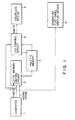
- a display control system according to the embodiment of the present invention is constituted such that the gradation flat panel display device 6 is disconnected from the computer 1, and a palette memory control circuit 2, a palette memory 3, an LCD (liquid crystal display) control circuit 4, and a color LCD device 5 are coupled to the computer 1 in place of the gradation flat panel display device 6.
- the gradation flat panel display device 6 is used to perform gradation display by display data from the computer 1.
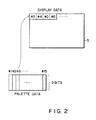
- the computer 1 outputs display data and palette data to the palette memory control circuit 2 and the LCD control circuit 4. Note that display data is used to designate a type of color to be displayed on the color LCD device 5, and palette data is used to display the color designated by the display data on the color LCD device 5.
- the palette memory control circuit 2 performs control to write palette data from the computer 1 into the palette memory 3.
- the palette memory 3 stores palette data under the control of the palette memory control circuit 2.
- the LCD control circuit 4 reads out palette data corresponding to a color designated by display data output from the computer 1, from the palette memory 3, and performs display control of the color LCD device 5 in accordance with the read out palette data.
- the color LCD device 5 is controlled by the LCD control circuit 4 to display a color indicated by palette data.
- the palette memory 3 is only required to have a storage capacity of about 9 bits x 16 words, the palette memory 3 need not be used as an external memory and can be realized by an internal register of the display control circuit.
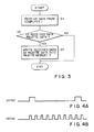
- step S1 when data is output from the computer 1, the data is received through a bus 7 (step S1), and it is checked whether or not the received data is palette data (step S2).
- palette data when palette data is to be written in the palette memory 3, the palette data is output to the same 4-bit bus 7 as that used to transmit display data because of the arrangement of the display control system shown in Fig. 1. For this reason, display data and palette data must be distinguished from each other.
- a data determining method for example, the following method is used: a method in which data received during a vertical blanking period in the color LCD device 5 is regarded as palette data; or a method in which when data is received during a period in which the signal polarities of a vertical synchronized signal VSYNC and a horizontal synchronized signal HSYNC in the color LCD device 5 are both positive, as shown in Figs. 4A and 4B, the received data is regarded as palette data (see United States Application Serial No. 355,613).
- step S2 If it is determined in step S2 that the received data is palette data, this data is written in the palette memory 3 as palette data.
- step S2 If it is determined in step S2 that the received data is not palette data, i.e., the received data is display data, this data is not written in the palette memory 3.
- the received data is not palette data, i.e., the received data is display data, this data is not written in the palette memory 3.
- 9-bit palette data In the LCD control circuit 4, 9-bit palette data
Landscapes
- Engineering & Computer Science (AREA)
- Theoretical Computer Science (AREA)
- Physics & Mathematics (AREA)
- General Physics & Mathematics (AREA)
- Human Computer Interaction (AREA)
- General Engineering & Computer Science (AREA)
- Computer Hardware Design (AREA)
- Controls And Circuits For Display Device (AREA)
- Control Of Indicators Other Than Cathode Ray Tubes (AREA)
- Digital Computer Display Output (AREA)
- Liquid Crystal Display Device Control (AREA)
Applications Claiming Priority (2)
| Application Number | Priority Date | Filing Date | Title |
|---|---|---|---|
| JP2040924A JPH03245187A (ja) | 1990-02-23 | 1990-02-23 | 表示装置 |
| JP40924/90 | 1990-02-23 |
Publications (2)
| Publication Number | Publication Date |
|---|---|
| EP0443581A2 true EP0443581A2 (fr) | 1991-08-28 |
| EP0443581A3 EP0443581A3 (en) | 1992-10-14 |
Family
ID=12594049
Family Applications (1)
| Application Number | Title | Priority Date | Filing Date |
|---|---|---|---|
| EP19910102551 Withdrawn EP0443581A3 (en) | 1990-02-23 | 1991-02-21 | Display control system |
Country Status (4)
| Country | Link |
|---|---|
| EP (1) | EP0443581A3 (fr) |
| JP (1) | JPH03245187A (fr) |
| KR (1) | KR940001669B1 (fr) |
| TW (1) | TW199210B (fr) |
Cited By (2)
| Publication number | Priority date | Publication date | Assignee | Title |
|---|---|---|---|---|
| WO1997037341A1 (fr) * | 1996-04-02 | 1997-10-09 | Arm Limited | Programmation de palettes d'affichage |
| GB2317310A (en) * | 1996-09-14 | 1998-03-18 | Ibm | Digital display driver by analog interface with reduced noise |
Family Cites Families (2)
| Publication number | Priority date | Publication date | Assignee | Title |
|---|---|---|---|---|
| WO1987007972A1 (fr) * | 1986-06-18 | 1987-12-30 | Technology Inc. 64 | Processeur d'affichage pour utilisation avec un ordinateur |
| JPH02226416A (ja) * | 1989-02-28 | 1990-09-10 | Toshiba Corp | カラー液晶表示制御装置 |
-
1990
- 1990-02-23 JP JP2040924A patent/JPH03245187A/ja active Pending
-
1991
- 1991-02-21 EP EP19910102551 patent/EP0443581A3/en not_active Withdrawn
- 1991-02-23 KR KR1019910002946A patent/KR940001669B1/ko not_active Expired - Lifetime
- 1991-03-08 TW TW080101868A patent/TW199210B/zh active
Cited By (5)
| Publication number | Priority date | Publication date | Assignee | Title |
|---|---|---|---|---|
| WO1997037341A1 (fr) * | 1996-04-02 | 1997-10-09 | Arm Limited | Programmation de palettes d'affichage |
| US6069611A (en) * | 1996-04-02 | 2000-05-30 | Arm Limited | Display palette programming utilizing frames of data which also contain color palette updating data to prevent display distortion or sparkle |
| GB2317310A (en) * | 1996-09-14 | 1998-03-18 | Ibm | Digital display driver by analog interface with reduced noise |
| US6097366A (en) * | 1996-09-14 | 2000-08-01 | International Business Machines Corporation | Analog display interface storing color values based upon user controlled calibration |
| GB2317310B (en) * | 1996-09-14 | 2000-11-22 | Ibm | Digital display driven by analog interface with reduced noise |
Also Published As
| Publication number | Publication date |
|---|---|
| TW199210B (fr) | 1993-02-01 |
| JPH03245187A (ja) | 1991-10-31 |
| KR940001669B1 (ko) | 1994-02-28 |
| KR920000029A (ko) | 1992-01-10 |
| EP0443581A3 (en) | 1992-10-14 |
Similar Documents
| Publication | Publication Date | Title |
|---|---|---|
| EP0185294A2 (fr) | Dispositif d'affichage | |
| KR100977044B1 (ko) | 컴퓨터시스템 및 그 제어방법 | |
| US6714172B2 (en) | Display control system and its control method, switching device, connection device, peripheral device, peripheral device system, and their control method, and computer readable memory | |
| KR20170111788A (ko) | 디스플레이 구동 회로 및 이를 포함하는 디스플레이 장치 | |
| EP0359234B1 (fr) | Appareil de commande d'affichage pour la conversion par hardware d'une résolution pour un T.R.C. en une résolution pour un panneau à plasma | |
| GB2231245A (en) | Apparatus for selecting mode of output in a computer system | |
| US6847335B1 (en) | Serial communication circuit with display detector interface bypass circuit | |
| EP0607778B1 (fr) | Dispositif de commande d'un panneau d'affichage à cristaux liquides capable d'afficher des images de petite taille | |
| US5285192A (en) | Compensation method and circuitry for flat panel display | |
| US6061048A (en) | Technique for automatically controlling the centering of monitor screen | |
| US6271827B1 (en) | Display system | |
| US5159327A (en) | Synchronous signal polarity converter of video card | |
| EP1836547A1 (fr) | Appareil d'affichage et son procede de commande | |
| EP0604536A1 (fr) | Procede permettant de commander un dispositif d'affichage dans un systeme d'affichage, et systeme et dispositif d'affichage | |
| EP1156469A2 (fr) | Dispositif de commande d'affichage | |
| CN117061795A (zh) | 信道接口edid随显示窗口分辨率自适应刷新的系统、方法 | |
| US5475808A (en) | Display control apparatus | |
| EP0443581A2 (fr) | Système de commande d'affichage | |
| US5635960A (en) | Horizontal position compensation circuit | |
| US20040189628A1 (en) | Liquid crystal display | |
| US6822637B2 (en) | Apparatus, method and program for generating image signal having pointer signal | |
| US5543823A (en) | Data storing method of a row buffer in on-screen display and control circuit thereof | |
| US4965563A (en) | Flat display driving circuit for a display containing margins | |
| US5818417A (en) | Automatic virtual display panning circuit for providing VGA display data to a lower resolution display and method therefor | |
| US5444458A (en) | Display data write control device |
Legal Events
| Date | Code | Title | Description |
|---|---|---|---|
| PUAI | Public reference made under article 153(3) epc to a published international application that has entered the european phase |
Free format text: ORIGINAL CODE: 0009012 |
|
| 17P | Request for examination filed |
Effective date: 19910318 |
|
| AK | Designated contracting states |
Kind code of ref document: A2 Designated state(s): DE FR GB |
|
| PUAL | Search report despatched |
Free format text: ORIGINAL CODE: 0009013 |
|
| AK | Designated contracting states |
Kind code of ref document: A3 Designated state(s): DE FR GB |
|
| STAA | Information on the status of an ep patent application or granted ep patent |
Free format text: STATUS: THE APPLICATION HAS BEEN WITHDRAWN |
|
| 18W | Application withdrawn |
Withdrawal date: 19940309 |