EP0443534B1 - Overload detection system for a machine tool - Google Patents
Overload detection system for a machine tool Download PDFInfo
- Publication number
- EP0443534B1 EP0443534B1 EP91102372A EP91102372A EP0443534B1 EP 0443534 B1 EP0443534 B1 EP 0443534B1 EP 91102372 A EP91102372 A EP 91102372A EP 91102372 A EP91102372 A EP 91102372A EP 0443534 B1 EP0443534 B1 EP 0443534B1
- Authority
- EP
- European Patent Office
- Prior art keywords
- drive
- driven
- toolholder
- teeth
- overload detection
- Prior art date
- Legal status (The legal status is an assumption and is not a legal conclusion. Google has not performed a legal analysis and makes no representation as to the accuracy of the status listed.)
- Expired - Lifetime
Links
Images


Classifications
-
- B—PERFORMING OPERATIONS; TRANSPORTING
- B23—MACHINE TOOLS; METAL-WORKING NOT OTHERWISE PROVIDED FOR
- B23Q—DETAILS, COMPONENTS, OR ACCESSORIES FOR MACHINE TOOLS, e.g. ARRANGEMENTS FOR COPYING OR CONTROLLING; MACHINE TOOLS IN GENERAL CHARACTERISED BY THE CONSTRUCTION OF PARTICULAR DETAILS OR COMPONENTS; COMBINATIONS OR ASSOCIATIONS OF METAL-WORKING MACHINES, NOT DIRECTED TO A PARTICULAR RESULT
- B23Q17/00—Arrangements for observing, indicating or measuring on machine tools
- B23Q17/09—Arrangements for observing, indicating or measuring on machine tools for indicating or measuring cutting pressure or for determining cutting-tool condition, e.g. cutting ability, load on tool
-
- B—PERFORMING OPERATIONS; TRANSPORTING
- B23—MACHINE TOOLS; METAL-WORKING NOT OTHERWISE PROVIDED FOR
- B23Q—DETAILS, COMPONENTS, OR ACCESSORIES FOR MACHINE TOOLS, e.g. ARRANGEMENTS FOR COPYING OR CONTROLLING; MACHINE TOOLS IN GENERAL CHARACTERISED BY THE CONSTRUCTION OF PARTICULAR DETAILS OR COMPONENTS; COMBINATIONS OR ASSOCIATIONS OF METAL-WORKING MACHINES, NOT DIRECTED TO A PARTICULAR RESULT
- B23Q11/00—Accessories fitted to machine tools for keeping tools or parts of the machine in good working condition or for cooling work; Safety devices specially combined with or arranged in, or specially adapted for use in connection with, machine tools
- B23Q11/04—Arrangements preventing overload of tools, e.g. restricting load
-
- F—MECHANICAL ENGINEERING; LIGHTING; HEATING; WEAPONS; BLASTING
- F16—ENGINEERING ELEMENTS AND UNITS; GENERAL MEASURES FOR PRODUCING AND MAINTAINING EFFECTIVE FUNCTIONING OF MACHINES OR INSTALLATIONS; THERMAL INSULATION IN GENERAL
- F16D—COUPLINGS FOR TRANSMITTING ROTATION; CLUTCHES; BRAKES
- F16D43/00—Automatic clutches
- F16D43/02—Automatic clutches actuated entirely mechanically
- F16D43/20—Automatic clutches actuated entirely mechanically controlled by torque, e.g. overload-release clutches, slip-clutches with means by which torque varies the clutching pressure
-
- Y—GENERAL TAGGING OF NEW TECHNOLOGICAL DEVELOPMENTS; GENERAL TAGGING OF CROSS-SECTIONAL TECHNOLOGIES SPANNING OVER SEVERAL SECTIONS OF THE IPC; TECHNICAL SUBJECTS COVERED BY FORMER USPC CROSS-REFERENCE ART COLLECTIONS [XRACs] AND DIGESTS
- Y10—TECHNICAL SUBJECTS COVERED BY FORMER USPC
- Y10T—TECHNICAL SUBJECTS COVERED BY FORMER US CLASSIFICATION
- Y10T408/00—Cutting by use of rotating axially moving tool
- Y10T408/13—Cutting by use of rotating axially moving tool with randomly-actuated stopping means
- Y10T408/14—Responsive to condition of Tool or tool-drive
Definitions
- the present invention relates generally to an overload detection system for a machine tool according to the pre-characterizing part of claim 1.
- Such system is known from EP-A-0 038 886.
- This prior art device needs two phase detectors, one for each gear.
- the device would become far simpler and less expensive in construction if it could do with a single phase detector.
- the two phase detectors have proved to be very easy to give rise to errors in the computation of the cutting torque, as the cuttings produced during machine tool operation unavoidably attach to and accumulate on them.
- JP-U-54-10060 proposes another cutting torque detection system.
- This second known system comprises a rotary member mounted fast on the spindle, a screw stud on a chuck support, and a torsion spring between the rotary member and the chuck support.
- the screw stud is rotatably engaged with the rotary member.
- the torsion spring yields when the cutting torque exceeds a predetermined limit, resulting in a relative phase displacement between rotary member and chuck support and, consequently, in the axial displacement of the screw stud. This axial displacement of the screw stud indicates the excessive torque on the cutting tool.
- JP-B-63-28742 teaches how to detect excessive thrust load on the cutting tool.
- a spool attached to a collet chuck is mounted within a hollow spindle for axial displace- ment relative to the same.
- the spindle has formed therein three fluid passageways to make up a thrust sensing valve in combination with the spool.
- the fluid passageways communicate with pressure operated switches which are selectively actuated upon linear displacement of the spool relative to the spindle in the event of the development of an excessive thrust load on the cutting tool.
- the overload detection system disclosed in the above-mentioned EP-A-0 038 886 comprises a torque detector.
- a torque detector When a drill member is subjected to a torque exceeding a preset value, the rotation of a spindle is delayed relative to a driving sleeve, so that a relative rotary movement takes place between the spindle and the sleeve (a relative phase displacement).
- cam surfaces provided on the spindle urge cam surfaces of a reaction rod to move the same axially rearward. Rotary movement is translated into axial movement.
- the present invention aims at the provision of an overload detection system for a machine tool that is simpler in construction and more reliable in operation than the listed prior art devices. This is achieved by the features of claim 1.
- the system of the present invention has the capability of both torque load and thrust load, besides being capable of detecting torque load only.
- the invention provides an overload detection system for a machine tool of the type having a drive spindle for imparting rotation to a cutting tool.
- the overload detection system comprises a tool-holder assembly which is broadly divided into a drive toolholder to be coupled to the drive spindle for joint rotation therewith, and a driven toolholder having means for holding a desired cutting tool such as a drill.
- the a driven toolholder is coupled to the drive toolholder so as to be at least rotatable relative to the same through a preassigned angle about a toolholder axis common to the drive spindle and the drive and the driven toolholders.
- a coiled torsion spring or like resilient means is provided for between drive toolholder and driven toolholder for torque transmission from the former to the latter.
- the drive and the driven toolholders have intermeshing teeth with clearances therebetween.
- a phase detector such as a proximity switch detects a relative phase displacement that will occur between the intermeshing teeth against the force of the torsion spring upon development of abnormal torque load on the cutting tool.
- the intermeshing teeth have bevels in sliding engagement with each other. Accordingly, a relative phase displacement also takes place between the two sets of teeth upon axial displacement of the driven toolholder toward the drive toolholder against the force of second resilient means, so that not only abnormal torque load but also abnormal thrust load on the cutting tool is detectable by the single phase detector.
- the invention also teaches an electronic overload detection circuit to be connected to the phase detector.
- the overload detection circuit produces a warning signal upon development of abnormal torque load, or abnormal thrust load, on the cutting tool.
- the machine tool itself needs no substantial alteration at all in construction, all that is required being to mount the toolholder assembly to the drive spindle of the machine tool and to mount the phase detector in a fixed position adjacent the circular path of the intermeshing teeth of the toolholder assembly. Therefore, the overload detection system of this invention finds universal use with machine tools of many different constructions. Any overload on the cutting tool is accurately detectable no matter how small the cutting tool may be in diameter.
- the illustrated machine tool has a spindlehead 15 with a drive spindle 17 rotatably mounted therein.
- the drive spindle 17 has a tapered hole 17 a for driving engagement with a toolholder assembly 1 constructed in accordance with the novel concepts of this invention.
- the toolholder assembly 1 comprises a drive toolholder 2 and a driven toolholder 21 held end to end in axial alignment and operatively coupled together in a manner to be detailed subsequently.
- the drive toolholder 2 has a tapered shank 2 a and a collar 3, both formed in one piece therewith.
- the tapered shank 2 a is snugly received in the hole 17 a of matching shape in the drive spindle 17.
- a thrust rod or shaft 4 is mounted in the hollow in the drive toolholder 2 extends into the driven toolholder 21 for rotatably supporting the same.
- the thrust rod 4 together with the driven toolholder 21 thereon is axially slidable in the hollow in the drive toolholder 2.
- a helical compression spring 5 butts endwise against the thrust rod 4. The compression spring 5 is to bear against the thrust load to be exerted on a cutting tool 13 (e.g.
- the compression spring 5 is to yield when the thrust load on the cutting tool 13 exceeds a predetermined limit, permitting the thrust rod 4 to retract to the right, as viewed in FIG. 1, with the cutting tool 13 and the driven toolholder 21.
- the driven toolholder 21 carries a collet chuck 23 of any known or suitable construction on its front or left hand end, as viewed in FIG. 1.
- the collet chuck 23 conventionally supports the cutting tool 13.
- the driven toolholder 21 is rotatably mounted to the thrust rod 4 via two combined thrust and radial ball bearings 9 and 10.
- a torque adjuster 28 of approximately tubular shape is coaxially mounted to the driven toolholder 21 via a connector tube 24 which is threadedly engaged with the driven toolholder.
- the torque adjuster 28 is capable of both angular and axial displacement relative to the connector tube 24 and hence to the driven toolholder 21.
- a helical compression spring 29 acts between drive toolholder 2 and torque adjuster 28 for biasing the latter forwardly into abutment against the driven toolholder 21 via the connector tube 24.
- the thrust rod 4 has its front end portion 6 shaped into frustoconical shape for engagement in the bearing 9. Slidably fitted over the thrust rod 4, a sleeve 7 has its rear end portion 8 also shaped into frustoconical shape for engagement in the other bearing 10.
- a helical compression spring 12 extends between a pair of spring retainers 7 a and 11.
- the spring retainer 7 a is formed in one piece with the sleeve 7.
- the other spring retainer 11 is fitted over the thrust rod 4 and locked against detachment therefrom by a collar 11 a on the thrust rod.
- the compression spring 12 acts to preload the bearings 9 and 10 via the frustoconical end portions 6 and 8 of the thrust rod 4 and the sleeve 7.
- a coiled torsion spring for torque transmission from drive toolholder 2 to driven toolholder 21.
- the torsion spring 25 has one end anchored to the drive toolholder 2 and the other end to the connector tube 24 on the driven toolholder 21.
- the following means are provided for the adjustment of the torsional strength of this torsion spring 25.
- the connector tube 24 has at least one, preferably two, lockpins 26 formed in diametrically opposite positions on its rear end face opposed to the torque adjuster 28.
- the lockpins 26 are capable of selective engagement in an annular row of blind holes 27 cut in the front end face of the torque adjuster 28 at constant angular spacings about the axis of the toolholder assembly 1. Normally, and as shown in FIG. 1, the lockpins 26 are engaged in two selected ones of the holes 27 under the bias of a helical compression spring 29 acting between drive toolholder 2 and torque adjuster 28.
- the torque adjuster 28 may first be backed away from the connector tube 24 against the force of the compression spring 29, thereby disengaging the lockpins 26 from the holes 27. Then the connector tube 24 may be revolved together with the driven toolholder 21 in either direction to a required angular position relative to the torque adjuster 28. Then the torque adjuster 28 may be allowed to travel forwardly under the force of the compression spring 29, with the consequent reengagement of the lockpins 26 in the two selected ones of the annular row of holes 27 in the torque adjuster.
- the capital 9 in FIG. 1 generally designates means for sensing the angular displacement of the driven toolholder 21 with respect to the drive toolholder 2.
- the description of this sensing means Q follows.
- the torque adjuster 28 has a plurality of, three in this particular embodiment, recesses 30 cut in its outer surface, thereby providing as many uncut portions or teeth 31 disposed at constant angular spacings about the axis of the toolholder assembly 1.
- the angular spacings between the torque adjuster teeth 31 are 120 degrees in this particular embodiment and are designated in FIG. 4.
- FIG. 4 also indicates that the drive toolholder 2 has a plurality of, three in this particular embodiment, teeth 34 extending parallel to the toolholder axis and received between the torque adjuster teeth 31.
- the teeth 34 on the drive toolholder 2 will be referred to as the drive teeth, and the teeth 31 on the torque adjuster 28 as the driven teeth, by way of contradistinction from each other.
- phase detector is disposed at 45 adjacent the path of the interdigitating drive teeth 34 and driven teeth 31 for detecting the relative phase displacement therebetween.
- the phase detector takes the form of a proximity switch in this and additional embodiments of the invention disclosed herein and will therefore be referred to as such hereinafter in this specification.
- Each drive tooth 34 has a central projection 35 extending toward the torque adjuster 28.
- Each projection 35 has a circumferential dimension less than that of each driven tooth 31, so that a pair of shoulders 40 are formed by each drive tooth 34 on both sides of its central projection 35.
- Three pairs of circumferential spacings 38 and 39 are thus defined between the opposite sides 32 and 33 of the driven teeth 31 and the opposite sides 36 and 37 of the projections 35 of the drive teeth 34.
- the proximity switch 45 is off when opposed to these spacings 38 and 39.
- Each driven tooth 31 has a bevel 31 a on one of its corners for abutting engagement with a bevel 40 a of one of the shoulders 40 of each drive tooth 34.
- These bevels 31 a and 40 a are to butt on each other under the force of the torsion spring 25, with a circumferential clearance a normally created between the side 40 b of each drive tooth 34 and the side 33 of each driven tooth 31.
- the bevels 31 a and 40 a constitute motion translating means 43 for translating the axial displacement of the driven toolholder 21, and hence of the torque adjuster 28, under excessive thrust load into the angular displacement of the driven teeth 31 relative to the drive teeth 34.
- such bevels may be formed on only either of the drive and driven teeth for sliding engagement with the required corners of the other of the drive and driven teeth.
- Other means could be employed as well for the accomplishment of the same objective.
- the required corners of the driven teeth 31 and drive teeth 34 might be rounded, instead of being beveled as in the illustrated embodiment.
- Another example might be guide slots and pins slidably engaged therein.
- each driven tooth 31, the projection 35 of each drive tooth 34, and the noted spacings 38 and 39 between the driven teeth and the projections of the drive teeth are normally all of the same circumferential dimension L , each spanning an angle of thirty degrees about the toolholder axis in this particular embodiment.
- the proximity switch 45 is bracketed at 16 to the spindlehead 15 and electrically connected to an overload detection circuit 50.
- a phototube may be employed in place of the proximity switch 45, provided that it be protected in any known or suitable way against the adverse effects of the cuttings and cutting oil during machine tool operation.
- the overload detection circuit 50 includes a spindle pulse generator 51 herein shown as a serial connection of a frequency to voltage converter (FVC) 52 and a voltage to frequency converter (VFC) 53.
- the proximity switch 45 is connected directly to the FVC 52.
- the spindle pulse generator 51 averages and multiplies the pulses generated by the proximity switch 45 and puts out a series of spindle pulses at a prescribed rate per revolution of the drive spindle 17.
- a gate circuit 54 has an input connected directly to the proximity switch 45 and another to the spindle pulse generator 51. The gate circuit 54 is open each time the proximity switch 45 is off, permitting the passage of the spindle pulses therethrough.
- the output of the gate circuit 54 is connected to a bidirectional counter 55, which has another input connected to the proximity switch 45 via an add/subtract switching circuit 56.
- This switching' circuit 56 causes the counter 55 to alternately add and subtract the incoming spindle pulses during the successive on-off cycles of the proximity switch 45.
- a comparator circuit 57 has three inputs connected respectively to the counter 55, the add/subtract switching circuit 56, and a setting circuit 58.
- the add/subtract switching circuit 56 delivers to the comparator circuit 57 a judgment command when the proximity switch 45 goes on.
- the comparator circuit 57 responds to this judgment command by judging whether or not the count of the counter 55 is more than a reference value that has been preset on the setting circuit 58.
- An output circuit 60 produces a warning signal if the counter count is more than the preset reference value.
- a reset circuit 59 functions to reset the counter each time the judgment has been made by the comparator circuit.
- the reference value to be preset on the setting circuit 58 may be equal to the difference, plus an allowable range of deviations, between the counts of the counter 55 when the proximity switch 45 is opposed to the spacings 38 and 39, FIG. 4, between the driven teeth 31 and the projections 35 of the drive teeth 34, with no load exerted on the cutting tool 13.
- This difference may be zero in this embodiment, so that the reference value may represent only an allowable range of deviations for the successive pulse counts to be made by the counter 55 during the operation of the machine tool.
- the overload detection circuit of FIG. 5 is susceptible to a variety of modifications within the broad teaching hereof.
- the spindle pulses may be obtained from the encoder, not shown, associated with the servomotor, also not shown, driving the spindle 17.
- other pulses may be input to the counter at a constant repetition rate from a suitable source of such pulses, and an overload detection signal may be produced when the difference between the pulse counts at the spacings 38 and 39 exceeds a reference value.
- the reference value must vary with the speed of revolution of the drive spindle 17, so that it may be amended with the spindle speed.
- the torque of the drive spindle 17 will be imparted directly to the drive toolholder 2 and thence, via the torsion spring 25, to the driven toolholder 21.
- the proximity switch 45 will alternately go on and off as the drive teeth 34, the driven teeth 31, and the spacings 38 and 39 therebetween travel past the proximity switch. Being spaced a considerable distance away from the cutting tool 13, the proximity switch 45 will function properly without being affected by the cuttings or by the cutting oil.
- the proximity switch 45 At A 1 in FIG. 6 is shown the proximity switch 45 to be off, being opposed to one spacing 38 between drive tooth 34 and driven tooth 31.
- the gate circuit 54 will be open during this time, as indicated at A 2 in FIG. 6, permitting the spindle pulses to pass therethrough into the bidirectional counter 55.
- the counter 55 Under the add command A 3 of the add/subtract switching circuit 56, the counter 55 will count the spindle pulses in an increasing direction, as at A 4.
- the proximity switch 45 will go on, as at A 5, when the projection 35 of one drive tooth 34 subsequently comes opposite the same. Then the gate circuit 54 will become closed, as at A 6, and the add/subtract switching circuit 56 will start the production of a subtract command A 7. Consequently, when the proximity switch 45 subsequently goes off, as at A 8, upon detection of the next spacing 39 between drive tooth 34 and driven tooth 31, the counter 55 will subtract (A 9) the incoming spindle pulses from the sum of such pulses that have been counted at A 4.
- the add/subtract switching circuit 56 will deliver a judgment command to the comparator circuit 57 when the proximity switch 45 subsequently goes on at A 10 upon detection of one driven tooth 31.
- the comparator circuit 57 will respond to this judgment command by comparing the count of the counter 55 with the reference value t that has been preset on the setting circuit 58.
- the cutting torque will exceed the value predetermined by the strength of the torsion spring 25 in the event of the blunting of the cutting tool 13, or of the excessive accumulation of the cuttings.
- a phase lag will occur between drive teeth 34 and driven teeth 31 because of the provision of the clearances a therebetween, and the sides 40 b of the drive teeth 34 will relatively move into abutment against the sides 33 of the driven teeth 31.
- the circumferential dimension of the spacings 38 therebetween will decrease to L - a whereas the circumferential dimension of the other spacings 39 will increase to L + a .
- FIG. 6 shows the spindle pulses being counted by the counter 55 in an increasing direction at B 1 and in a decreasing direction at B 2 in the event of the above noted abnormal increase in cutting torque.
- the resulting count will be equivalent to -2 a , as indicated at B 3. Since the absolute value of this count will be more than the preset reference value t , the output circuit 60 will go high to give a warning C against excessive torque.
- the warning signal C may be utilized in any convenient way.
- the unshown spindle drive motor may be set out of rotation, or a stepback command may be generated, in response to the warning signal.
- an additional counter may be provided for counting the warnings made by the overload detection circuit 50, and the cutting tool 13 may be replaced whenever such warnings have been counted to a predetermined number.
- the counter 55 may count the spindle pulses in an increasing direction when the proximity switch 45 is opposed to the spacing 39, and in a decreasing direction when the proximity switch is opposed to the spacing 38.
- the resulting count at B 6 will be +2 a in this case.
- the comparator circuit 57 compares the absolute value of the count with the reference value t , the output circuit 60 will generate the desired warning C . All the required functions of the overload detection circuit 50 may be performed by a preprogrammed computer within the scope of this invention.
- the counter 55 in the event of the development of abnormal cutting torque, the counter 55 produces an output equivalent to twice the clearance a between drive teeth 34 and driven teeth 31. Overload will therefore be infallibly detected through minimal relative phase displacement between the drive and the driven teeth. In other words, a minimal increase in cutting torque in excess of the value determined by the torsion spring 25 will be sensed in an instant, making it possible to make any necessary countermeasure without delay.
- the toolholder assembly 1 of FIGS. 1-4 is also constructed for the detection of excessive thrust loading on the cutting tool 13, as in the event of its wearout.
- the compression spring 5 behind the thrust rod 4 will be fully extended in the absence of such excessive thrust load, holding the drive teeth 34 and driven teeth 31 in their relative positions indicated by the solid lines in FIG. 4.
- the compression spring 5 will yield, permitting the thrust rod 4 to retract to the right, as viewed in FIG. 1, with the driven toolholder 21 relative to the drive toolholder 2.
- the consequent rearward displacement of the driven teeth 31 will be translated into their angular displacement relative to the drive teeth 34 as the bevels 31 a of the driven teeth slide on the bevels 40 a of the drive teeth.
- the angle of such rotation of the driven teeth 31 corresponds to the clearances a between the drive and the driven teeth.
- the overload detection circuit 50 of FIG. 5 can therefore detect the abnormal thrust load, producing the warning C through the procedure set forth above with reference to FIG. 6.
- the relative phase displacement of the drive and the driven teeth is utilized for the detection of both angular and axial overloads on the cutting tool.
- the construction of the toolholder assembly can therefore be much simpler than heretofore, and the single proximity switch with the associated overload detection circuit suffices to give warnings upon development of both angular and axial overloads.
Landscapes
- Engineering & Computer Science (AREA)
- Mechanical Engineering (AREA)
- General Engineering & Computer Science (AREA)
- Machine Tool Sensing Apparatuses (AREA)
- Gripping On Spindles (AREA)
- Force Measurement Appropriate To Specific Purposes (AREA)
Description
- The present invention relates generally to an overload detection system for a machine tool according to the pre-characterizing part of claim 1. Such system is known from EP-A-0 038 886.
- A variety of overload detection systems have been suggested and used with machine tools. Among such known systems is the one described and claimed in Japanese Unexamined Patent Publication No. 59-142049. This prior art device teaches the use of two gears for detecting abnormal torque load on the cutting tool. The first of the two gears is mounted fast on the toolholder for joint rotation therewith. The second gear is coupled to the first gear via elastic means that is subject to torsional deformation in proportion with the cutting torque. The phases of the two gears are detected by respective phase detectors such as proximity switches. The cutting torque is computed electronically on the basis of the phase difference between the gears for comparison with a normal range of torque values.
- This prior art device needs two phase detectors, one for each gear. The device would become far simpler and less expensive in construction if it could do with a single phase detector. Moreover, as used in the prior art device, the two phase detectors have proved to be very easy to give rise to errors in the computation of the cutting torque, as the cuttings produced during machine tool operation unavoidably attach to and accumulate on them.
- JP-U-54-10060 proposes another cutting torque detection system. This second known system comprises a rotary member mounted fast on the spindle, a screw stud on a chuck support, and a torsion spring between the rotary member and the chuck support. The screw stud is rotatably engaged with the rotary member. The torsion spring yields when the cutting torque exceeds a predetermined limit, resulting in a relative phase displacement between rotary member and chuck support and, consequently, in the axial displacement of the screw stud. This axial displacement of the screw stud indicates the excessive torque on the cutting tool.
- This conventional system is also objectionable for the following reasons. The rotary member and the chuck support must be capable of relative phase displacement through a considerably great angle in order to cause axial displacement of the screw stud upon development of excessive cutting torque. Such excessive cutting torque must therefore be very high in comparison with the yielding point of the torsion spring. An additional inconvenience is that it takes an inconveniently prolonged time for the rotary member and the chuck support to undergo relative phase displacement through the required great angle. Consequently, this prior art system fails to set the drive spindle out of rotation instantly upon development of any excessive torque.
- JP-B-63-28742 teaches how to detect excessive thrust load on the cutting tool. To this end a spool attached to a collet chuck is mounted within a hollow spindle for axial displace- ment relative to the same. The spindle has formed therein three fluid passageways to make up a thrust sensing valve in combination with the spool. The fluid passageways communicate with pressure operated switches which are selectively actuated upon linear displacement of the spool relative to the spindle in the event of the development of an excessive thrust load on the cutting tool.
- This prior art system is subject to the drawback that complex construction is required solely for the detection of abnormal thrust load. Additional means are needed for the detection of excessive torque load, making the machine tool even more complex and expensive in construction.
- The overload detection system disclosed in the above-mentioned EP-A-0 038 886 comprises a torque detector. When a drill member is subjected to a torque exceeding a preset value, the rotation of a spindle is delayed relative to a driving sleeve, so that a relative rotary movement takes place between the spindle and the sleeve (a relative phase displacement). As a result, cam surfaces provided on the spindle urge cam surfaces of a reaction rod to move the same axially rearward. Rotary movement is translated into axial movement.
- The present invention aims at the provision of an overload detection system for a machine tool that is simpler in construction and more reliable in operation than the listed prior art devices. This is achieved by the features of claim 1.
- The system of the present invention has the capability of both torque load and thrust load, besides being capable of detecting torque load only.
- Stated briefly, the invention provides an overload detection system for a machine tool of the type having a drive spindle for imparting rotation to a cutting tool. The overload detection system comprises a tool-holder assembly which is broadly divided into a drive toolholder to be coupled to the drive spindle for joint rotation therewith, and a driven toolholder having means for holding a desired cutting tool such as a drill. The a driven toolholder is coupled to the drive toolholder so as to be at least rotatable relative to the same through a preassigned angle about a toolholder axis common to the drive spindle and the drive and the driven toolholders. A coiled torsion spring or like resilient means is provided for between drive toolholder and driven toolholder for torque transmission from the former to the latter. The drive and the driven toolholders have intermeshing teeth with clearances therebetween. A phase detector such as a proximity switch detects a relative phase displacement that will occur between the intermeshing teeth against the force of the torsion spring upon development of abnormal torque load on the cutting tool.
- The intermeshing teeth have bevels in sliding engagement with each other. Accordingly, a relative phase displacement also takes place between the two sets of teeth upon axial displacement of the driven toolholder toward the drive toolholder against the force of second resilient means, so that not only abnormal torque load but also abnormal thrust load on the cutting tool is detectable by the single phase detector.
- The invention also teaches an electronic overload detection circuit to be connected to the phase detector. The overload detection circuit produces a warning signal upon development of abnormal torque load, or abnormal thrust load, on the cutting tool.
- Thus, according to the invention, the machine tool itself needs no substantial alteration at all in construction, all that is required being to mount the toolholder assembly to the drive spindle of the machine tool and to mount the phase detector in a fixed position adjacent the circular path of the intermeshing teeth of the toolholder assembly. Therefore, the overload detection system of this invention finds universal use with machine tools of many different constructions. Any overload on the cutting tool is accurately detectable no matter how small the cutting tool may be in diameter.
- The above and other features and advantages of this invention and the manner of realizing them will become more apparent, and the invention itself will best be understood, from a study of the following description and appended claims, with reference had to the attached drawings showing some preferable embodiments of the invention.
-
- FIG. 1 is an axial section through the toolholder assembly constructed in accordance with the novel concepts of this invention, the toolholder assembly being shown mounted to the drive spindle of a machine tool and also shown together with a proximity switch forming a part of the overload detection system;
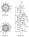
- FIG. 2 is a cross section through the toolholder assembly, taken along the line II-II in FIG. 1;
- FIG. 3 is another cross section through the toolholder assembly, taken along the line III-III in FIG. 1;
- FIG. 4 is a developed diagram of the interdigitating teeth of the toolholder assembly;
- FIG. 5 is a block diagram of the overload detection circuit for use with the toolholder assembly of FIG. 1; and
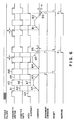
- FIG. 6 is a timing diagram useful in explaining the operation of the overload detection system of FIGS. 1-5.
- With reference first and in particular to FIG. 1, the illustrated machine tool has a
spindlehead 15 with a drive spindle 17 rotatably mounted therein. The drive spindle 17 has atapered hole 17a for driving engagement with a toolholder assembly 1 constructed in accordance with the novel concepts of this invention. The toolholder assembly 1 comprises adrive toolholder 2 and a driventoolholder 21 held end to end in axial alignment and operatively coupled together in a manner to be detailed subsequently. - Generally in the form of a hollow shaft, the
drive toolholder 2 has atapered shank 2a and a collar 3, both formed in one piece therewith. Thetapered shank 2a is snugly received in thehole 17a of matching shape in the drive spindle 17. A thrust rod or shaft 4 is mounted in the hollow in thedrive toolholder 2 extends into the driventoolholder 21 for rotatably supporting the same. In this particular embodiment the thrust rod 4 together with the driventoolholder 21 thereon is axially slidable in the hollow in thedrive toolholder 2. Also mounted in the hollow in thedrive toolholder 2, a helical compression spring 5 butts endwise against the thrust rod 4. The compression spring 5 is to bear against the thrust load to be exerted on a cutting tool 13 (e.g. drill) carried by the driventoolholder 21 in the operation of the machine tool. The compression spring 5 is to yield when the thrust load on thecutting tool 13 exceeds a predetermined limit, permitting the thrust rod 4 to retract to the right, as viewed in FIG. 1, with the cuttingtool 13 and the driventoolholder 21. - Approximately tubular in shape, the driven
toolholder 21 carries acollet chuck 23 of any known or suitable construction on its front or left hand end, as viewed in FIG. 1. Thecollet chuck 23 conventionally supports thecutting tool 13. The driventoolholder 21 is rotatably mounted to the thrust rod 4 via two combined thrust andradial ball bearings 9 and 10. Atorque adjuster 28 of approximately tubular shape is coaxially mounted to the driventoolholder 21 via aconnector tube 24 which is threadedly engaged with the driven toolholder. Thetorque adjuster 28 is capable of both angular and axial displacement relative to theconnector tube 24 and hence to the driventoolholder 21. Ahelical compression spring 29 acts betweendrive toolholder 2 andtorque adjuster 28 for biasing the latter forwardly into abutment against the driventoolholder 21 via theconnector tube 24. - The thrust rod 4 has its front end portion 6 shaped into frustoconical shape for engagement in the bearing 9. Slidably fitted over the thrust rod 4, a
sleeve 7 has itsrear end portion 8 also shaped into frustoconical shape for engagement in theother bearing 10. - A
helical compression spring 12 extends between a pair ofspring retainers 7a and 11. Thespring retainer 7a is formed in one piece with thesleeve 7. The other spring retainer 11 is fitted over the thrust rod 4 and locked against detachment therefrom by a collar 11a on the thrust rod. Thecompression spring 12 acts to preload thebearings 9 and 10 via thefrustoconical end portions 6 and 8 of the thrust rod 4 and thesleeve 7. - At 25 is seen a coiled torsion spring for torque transmission from
drive toolholder 2 to driventoolholder 21. Thetorsion spring 25 has one end anchored to thedrive toolholder 2 and the other end to theconnector tube 24 on the driventoolholder 21. The following means are provided for the adjustment of the torsional strength of thistorsion spring 25. - As will be understood from both FIGS. 1 and 2, the
connector tube 24 has at least one, preferably two, lockpins 26 formed in diametrically opposite positions on its rear end face opposed to thetorque adjuster 28. Thelockpins 26 are capable of selective engagement in an annular row ofblind holes 27 cut in the front end face of thetorque adjuster 28 at constant angular spacings about the axis of the toolholder assembly 1. Normally, and as shown in FIG. 1, thelockpins 26 are engaged in two selected ones of theholes 27 under the bias of ahelical compression spring 29 acting betweendrive toolholder 2 andtorque adjuster 28. - Therefore, for the adjustment of the torsional strength of the
torsion spring 25, thetorque adjuster 28 may first be backed away from theconnector tube 24 against the force of thecompression spring 29, thereby disengaging thelockpins 26 from theholes 27. Then theconnector tube 24 may be revolved together with the driventoolholder 21 in either direction to a required angular position relative to thetorque adjuster 28. Then thetorque adjuster 28 may be allowed to travel forwardly under the force of thecompression spring 29, with the consequent reengagement of thelockpins 26 in the two selected ones of the annular row ofholes 27 in the torque adjuster. - The capital 9 in FIG. 1 generally designates means for sensing the angular displacement of the driven
toolholder 21 with respect to thedrive toolholder 2. The description of this sensing means Q follows. - As best revealed by FIG. 3, the
torque adjuster 28 has a plurality of, three in this particular embodiment, recesses 30 cut in its outer surface, thereby providing as many uncut portions orteeth 31 disposed at constant angular spacings about the axis of the toolholder assembly 1. The angular spacings between thetorque adjuster teeth 31 are 120 degrees in this particular embodiment and are designatedin FIG. 4.
- FIG. 4 also indicates that the
drive toolholder 2 has a plurality of, three in this particular embodiment,teeth 34 extending parallel to the toolholder axis and received between thetorque adjuster teeth 31. Hereinafter in this specification, theteeth 34 on thedrive toolholder 2 will be referred to as the drive teeth, and theteeth 31 on thetorque adjuster 28 as the driven teeth, by way of contradistinction from each other. - As will be seen from both FIGS. 1 and 4, a phase detector is disposed at 45 adjacent the path of the interdigitating
drive teeth 34 and driventeeth 31 for detecting the relative phase displacement therebetween. The phase detector takes the form of a proximity switch in this and additional embodiments of the invention disclosed herein and will therefore be referred to as such hereinafter in this specification. - Each
drive tooth 34 has acentral projection 35 extending toward thetorque adjuster 28. Eachprojection 35 has a circumferential dimension less than that of each driventooth 31, so that a pair ofshoulders 40 are formed by eachdrive tooth 34 on both sides of itscentral projection 35. Three pairs ofcircumferential spacings opposite sides teeth 31 and theopposite sides projections 35 of thedrive teeth 34. Theproximity switch 45 is off when opposed to thesespacings - Each driven
tooth 31 has abevel 31a on one of its corners for abutting engagement with abevel 40a of one of theshoulders 40 of eachdrive tooth 34. Thesebevels torsion spring 25, with a circumferential clearance a normally created between theside 40b of eachdrive tooth 34 and theside 33 of each driventooth 31. Thebevels toolholder 21, and hence of thetorque adjuster 28, under excessive thrust load into the angular displacement of the driventeeth 31 relative to thedrive teeth 34. Therefore, only if this objective is accomplished, such bevels may be formed on only either of the drive and driven teeth for sliding engagement with the required corners of the other of the drive and driven teeth. Other means could be employed as well for the accomplishment of the same objective. As an example of such alternative means, the required corners of the driventeeth 31 and driveteeth 34 might be rounded, instead of being beveled as in the illustrated embodiment. Another example might be guide slots and pins slidably engaged therein. - As will be also noted from FIG. 4, each driven
tooth 31, theprojection 35 of eachdrive tooth 34, and thenoted spacings - With reference back to FIG. 1 the
proximity switch 45 is bracketed at 16 to thespindlehead 15 and electrically connected to anoverload detection circuit 50. In practice a phototube may be employed in place of theproximity switch 45, provided that it be protected in any known or suitable way against the adverse effects of the cuttings and cutting oil during machine tool operation. - Reference is now directed to the block diagram of FIG. 5 for the detailed study of the
overload detection circuit 50 illustrated therein. Theoverload detection circuit 50 includes aspindle pulse generator 51 herein shown as a serial connection of a frequency to voltage converter (FVC) 52 and a voltage to frequency converter (VFC) 53. Theproximity switch 45 is connected directly to theFVC 52. Thespindle pulse generator 51 averages and multiplies the pulses generated by theproximity switch 45 and puts out a series of spindle pulses at a prescribed rate per revolution of the drive spindle 17. - A
gate circuit 54 has an input connected directly to theproximity switch 45 and another to thespindle pulse generator 51. Thegate circuit 54 is open each time theproximity switch 45 is off, permitting the passage of the spindle pulses therethrough. - The output of the
gate circuit 54 is connected to abidirectional counter 55, which has another input connected to theproximity switch 45 via an add/subtract switchingcircuit 56. This switching'circuit 56 causes thecounter 55 to alternately add and subtract the incoming spindle pulses during the successive on-off cycles of theproximity switch 45. - A
comparator circuit 57 has three inputs connected respectively to thecounter 55, the add/subtract switchingcircuit 56, and asetting circuit 58. The add/subtract switchingcircuit 56 delivers to the comparator circuit 57 a judgment command when theproximity switch 45 goes on. Thecomparator circuit 57 responds to this judgment command by judging whether or not the count of thecounter 55 is more than a reference value that has been preset on thesetting circuit 58. Anoutput circuit 60 produces a warning signal if the counter count is more than the preset reference value. Connected betweencomparator circuit 57 andcounter 55, areset circuit 59 functions to reset the counter each time the judgment has been made by the comparator circuit. - The reference value to be preset on the
setting circuit 58 may be equal to the difference, plus an allowable range of deviations, between the counts of thecounter 55 when theproximity switch 45 is opposed to thespacings teeth 31 and theprojections 35 of thedrive teeth 34, with no load exerted on thecutting tool 13. This difference may be zero in this embodiment, so that the reference value may represent only an allowable range of deviations for the successive pulse counts to be made by thecounter 55 during the operation of the machine tool. - The overload detection circuit of FIG. 5 is susceptible to a variety of modifications within the broad teaching hereof. For instance, the spindle pulses may be obtained from the encoder, not shown, associated with the servomotor, also not shown, driving the spindle 17. Also, instead of the spindle pulses produced as above stated, other pulses may be input to the counter at a constant repetition rate from a suitable source of such pulses, and an overload detection signal may be produced when the difference between the pulse counts at the
spacings - The following operational description of the overload detection system, constructed as so far described with reference to FIGS. 1-5, will be better understood by referring also to the timing diagram of FIG. 6.
- During the normal cutting operation of the machine tool illustrated in FIG. 1, the torque of the drive spindle 17 will be imparted directly to the
drive toolholder 2 and thence, via thetorsion spring 25, to the driventoolholder 21. Thus theproximity switch 45 will alternately go on and off as thedrive teeth 34, the driventeeth 31, and thespacings tool 13, theproximity switch 45 will function properly without being affected by the cuttings or by the cutting oil. - At A₁ in FIG. 6 is shown the
proximity switch 45 to be off, being opposed to onespacing 38 betweendrive tooth 34 and driventooth 31. Thegate circuit 54 will be open during this time, as indicated at A₂ in FIG. 6, permitting the spindle pulses to pass therethrough into thebidirectional counter 55. Under the add command A₃ of the add/subtract switchingcircuit 56, thecounter 55 will count the spindle pulses in an increasing direction, as at A₄. - The
proximity switch 45 will go on, as at A₅, when theprojection 35 of onedrive tooth 34 subsequently comes opposite the same. Then thegate circuit 54 will become closed, as at A₆, and the add/subtract switchingcircuit 56 will start the production of a subtract command A₇. Consequently, when theproximity switch 45 subsequently goes off, as at A₈, upon detection of thenext spacing 39 betweendrive tooth 34 and driventooth 31, thecounter 55 will subtract (A₉) the incoming spindle pulses from the sum of such pulses that have been counted at A₄. - The add/subtract switching
circuit 56 will deliver a judgment command to thecomparator circuit 57 when theproximity switch 45 subsequently goes on at A₁₀ upon detection of one driventooth 31. Thecomparator circuit 57 will respond to this judgment command by comparing the count of thecounter 55 with the reference value t that has been preset on thesetting circuit 58. - Let us assume that the illustrated machine tool has been operating normally, with no excessive torque exerted on the
cutting tool 13. In that case, as will be understood from FIG. 4, thebevels teeth torsion spring 25. Therefore, thespacings teeth counter 55 was zero at the end of the subtraction at A₉. Therefore, theoverload detection circuit 50 will remain low, having detected no abnormal torque. - The cutting torque will exceed the value predetermined by the strength of the
torsion spring 25 in the event of the blunting of thecutting tool 13, or of the excessive accumulation of the cuttings. Thereupon a phase lag will occur betweendrive teeth 34 and driventeeth 31 because of the provision of the clearances a therebetween, and thesides 40b of thedrive teeth 34 will relatively move into abutment against thesides 33 of the driventeeth 31. As a result of this relative phase displacement betweendrive teeth 34 and driventeeth 31, the circumferential dimension of thespacings 38 therebetween will decrease to L - a whereas the circumferential dimension of theother spacings 39 will increase to L + a. - FIG. 6 shows the spindle pulses being counted by the
counter 55 in an increasing direction at B₁ and in a decreasing direction at B₂ in the event of the above noted abnormal increase in cutting torque. The resulting count will be equivalent to -2a, as indicated at B₃. Since the absolute value of this count will be more than the preset reference value t, theoutput circuit 60 will go high to give a warning C against excessive torque. - The warning signal C may be utilized in any convenient way. For example, the unshown spindle drive motor may be set out of rotation, or a stepback command may be generated, in response to the warning signal. Also, an additional counter may be provided for counting the warnings made by the
overload detection circuit 50, and thecutting tool 13 may be replaced whenever such warnings have been counted to a predetermined number. - Possibly, as indicated at B₄ and B₅ in FIG. 6, the
counter 55 may count the spindle pulses in an increasing direction when theproximity switch 45 is opposed to thespacing 39, and in a decreasing direction when the proximity switch is opposed to thespacing 38. The resulting count at B₆ will be +2a in this case. However, since thecomparator circuit 57 compares the absolute value of the count with the reference value t, theoutput circuit 60 will generate the desired warning C. All the required functions of theoverload detection circuit 50 may be performed by a preprogrammed computer within the scope of this invention. - It is to be noted that in the event of the development of abnormal cutting torque, the
counter 55 produces an output equivalent to twice the clearance a betweendrive teeth 34 and driventeeth 31. Overload will therefore be infallibly detected through minimal relative phase displacement between the drive and the driven teeth. In other words, a minimal increase in cutting torque in excess of the value determined by thetorsion spring 25 will be sensed in an instant, making it possible to make any necessary countermeasure without delay. - The toolholder assembly 1 of FIGS. 1-4 is also constructed for the detection of excessive thrust loading on the
cutting tool 13, as in the event of its wearout. The compression spring 5 behind the thrust rod 4 will be fully extended in the absence of such excessive thrust load, holding thedrive teeth 34 and driventeeth 31 in their relative positions indicated by the solid lines in FIG. 4. - Then, upon development of abnormal thrust load, the compression spring 5 will yield, permitting the thrust rod 4 to retract to the right, as viewed in FIG. 1, with the driven
toolholder 21 relative to thedrive toolholder 2. As will be understood by referring again to FIG. 4, the consequent rearward displacement of the driventeeth 31 will be translated into their angular displacement relative to thedrive teeth 34 as thebevels 31a of the driven teeth slide on thebevels 40a of the drive teeth. The angle of such rotation of the driventeeth 31 corresponds to the clearances a between the drive and the driven teeth. - Thus, as in the above described case of the development of excessive torque load on the
cutting tool 13, a difference is created between the circumferential dimensions of each pair ofspacings overload detection circuit 50 of FIG. 5 can therefore detect the abnormal thrust load, producing the warning C through the procedure set forth above with reference to FIG. 6. - Among the most pronounced features of this embodiment is that. the relative phase displacement of the drive and the driven teeth is utilized for the detection of both angular and axial overloads on the cutting tool. The construction of the toolholder assembly can therefore be much simpler than heretofore, and the single proximity switch with the associated overload detection circuit suffices to give warnings upon development of both angular and axial overloads.
Claims (14)
- An overload detection system for a machine tool, the system comprising: a toolholder assembly (1) which is divided into a drive toolholder (2) coupled to a drive spindle (17) for joint rotation therewith and a driven toolholder (21) having means (23) for holding a cutting tool (13), the driven toolholder being coupled to the drive toolholder so as to be rotatable relative to the same through a preassigned angle about a toolholder axis, wherein first resilient means (25) is provided between the drive and the driven toolholders for torque transmission from the former to the latter, and wherein a phase detector (45) is provided for detecting a relative phase displacement that will occur between the drive toolholder (2) and the driven holder (21) against the force of the resilient means (25) upon development of abnormal torque load on the cutting tool (13),
characterized in that
the driven toolholder (21) is biased away from the drive toolholder (2) by second resilient means (5), the second resilient means yielding to permit the axial displacement of the driven toolholder toward the drive toolholder upon development of abnormal thrust load on the cutting tool (13) , a set of drive-side teeth (34) are formed on the drive toolholder (2) at constant circumferential spacings about the toolholder axis, and a set of driven-side teeth (31) are formed on the driven toolholder (21) at constant circumferential spacings about the toolholder axis and arranged intermeshingly with the drive-side teeth (34) with clearances (a,b or c) therebetween, that the driven toolholder (21) with the driven teeth (31) thereon is axially movable toward and away from the drive toolholder (2) within limits, that said phase detector (46) operates to detect a relative phase displacement between the drive-side and driven-side teeth (34,31), and that motion translating means (31a,40a) acts between the drive and the driven toolholders for causing a relative phase displacement between the drive-side and the driven-side teeth against the force of the first resilient means (25) upon axial displacement of the driven toolholder (21) toward the drive toolholder (2) against the bias of the second resilient means (5), so that not only abnormal torque load but also abnormal thrust load on the cutting tool (13) is detectable by the phase detector (45) on the basis of a relative phase displacement between the drive-side and the driven-side teeth, - An overload detection system of claim 1 wherein the motion translating means comprises bevels (31a or 40a) formed on at least either of the drive and driven teeth (31, 34) for sliding engagement with the other of the drive and driven teeth.
- An overload dectection system as claimed in claims 1 or 2, characterized in that the phase detector (45) is a proximity switch.
- An overload detection system as claimed in claim 3, wherein the machine tool has a spindlehead (15) to which the drive spindle (17) is rotatably mounted, characterized in that the proximity switch (45) is mounted to the spindlehead (15).
- An overload dectection system as claimed in any one of claims 1 to 4, characterized in that an overload detection circuit (50) is connected to the phase detector (45) for producing a warning signal (C) upon detection of a relative phase displacement between the drive and the driven teeth (31, 34) by the phase detector.
- An overload detection system as claimed in any one of claims 1 to 5, characterized in that either of the drive and the driven teeth (31, 34) have each a projection (35) loosely received between two neighboring ones of the other of the drive and the driven teeth to provide a pair of spacings (38, 39) therebetween, and that the phase detector (45) detects a relative phase displacement between the drive and the driven teeth on the basis of the circumferential dimensions of each pair of spacings between the drive and the driven teeth.
- An overload detection system as claimed in claim 6, characterized in that an overload detection circuit (50) is connected to the phase detector (45) for producing a warning signal (C) upon detection of a relative phase displacement between the drive and the driven teeth (34,31) by the phase detector, the overload detection circuit comprising a pulse generator (51) for generating a series of spindle pulses at a prescribed repetition rate, a bidirectional counter (55) for counting the spindle pulses in one direction when the phase detector is opposed to one of each pair of spacings (38, 39) between the drive and the driven teeth, and in the other direction when the phase detector is opposed to the other of each pair of spacings between the drive and the driven teeth, and a comparator circuit (57) for comparing the spindle pulse count of the bidirectional counter with a preset reference value.
- An overload detection system as claimed in any one of claims 1 to 5, characterized in that either of the drive and the driven teeth (31, 34) are all of constant circumferential dimension, that the other of the drive and the driven teeth are each divided into a wider tooth section and a narrower tooth section which are both received between two neighboring ones of said either of the drive and the driven teeth, with the clearance (b) normally created between each narrower tooth section and one of said either of the drive and the driven teeth, the sum (L) of the circumferential dimensions of each wider tooth section and one of said either of the drive and the driven teeth being equal to the sum (L) of the clearance and the circumferential dimensions of each narrower tooth section and one of said either of the drive and the driven teeth, and that the clearance (b) normally created between each narrower tooth section and one of said either of the drive and the driven teeth is sufficiently small to be per se undetectable by the phase detector (45).
- An overload detection system as claimed in claim 8, characterized in that an overload detection circuit (50) is connected to the phase detector (45) for producing a warning signal (C) upon detection of a relative phase displacement between the drive and the driven teeth by the phase detector, the overload detection circuit comprising a pulse generator (51) for generating a series of spindle pulses at a prescribed repetition rate, a bidirectional counter (55) for counting the spindle pulses in one direction when the phase detector is opposed to each wider tooth section (34) and an adjacent one (31) of said either of the drive and the driven teeth, and in the other direction when the phase detector is opposed to each narrower tooth section (34) and an adjacent one (31) of said either of the drive and the driven teeth, and a comparator circuit (57) for comparing the spindle pulse count of the bidirecational counter with a preset reference value.
- An overload detection system as claimed in any one of claims 1 to 5, characterized in that either of the drive and the driven teeth (31, 34) have each a projecion (35) loosely received between two neighboring ones of the other of the drive and the driven teeth to provide a spacing on one side of the projection, and that the phase detector detects a relative phase displacement between the drive and the driven teeth on the basis of the circumferential dimensions of each projection (35) and an adjacent one (31) of said other of the drive and the driven teeth, or of the circumferential dimension of each spacing between one projection (35) and an adjacent one (31) of said other of the drive and the driven teeth.
- An overload detection system as claimed in claim 10, characterized in that an overload detection circuit (50) is connected to the phase detector (45) for producing a warning signal upon detection of a relative phase displacement between the drive and the driven teeth (31, 34) by the phase detector, the overload detection circuit comprising a pulse generator (51) for generating a series of spindle pulses at a prescribed repetition rate, a counter (55a) for counting the spindle pulses when the phase detector is opposed to each projection (35) and an adjacent one (31) of said other of the drive and the driven teeth, or to each spacing between one projection (35) and an adjacent one (31) of said other of the drive and the drive teeth, and a comparator circuit (57a) for comparing the spindle pulse count of the counter (55a) with a preset reference value.
- An overload detection system as claimed in any one of claims 1 to 11, characterized in that the resilient means (25) is a coiled torsion spring anchored at one end to the first drive toolholder (2) and at another end to the driven toolholder (21), that the set of driven teeth (31) are formed on a torque adjuster (28) of annular shape which is disposed coaxially between the drive toolholder (2) and the driven toolholder (21) for both axial and rotary displacement relative to the drive and the driven toolholders, and that selective engagement means (26, 27 and 29) are provided for locking together the driven toolholder (21) and the torque adjuster (28) against rotation relative to each other in a selected angular position of the driven toolholder relative to the drive toolholder (2) in order to adjustably vary the resistance offered by the torsion spring (25) against load torque on the cutting tool (13).
- An overload detection system as claimed in claim 12, characterized in that the selective engagement means comprises at least one lockpin (26) formed on either of the driven toolholder (21) and the torque adjuster (28) for selective engagement in a row of holes (27) formed in annular arrangement in the other of the driven toolholder and the torque adjuster, and third resilient means (29) for urging the torque adjuster against the driven toolholder.
- An overload detection system as claimed in any one of the claims 1 to 13, characterized in that the drive toolholder (2) has a thrust rod (4) mounted coaxially therein and extending into the driven toolholder (21), that the driven toolholder is rotatably mounted on the thrust rod via a first (9) and a second (10) radial and thrust bearing, the thrust rod having an end portion (6) of frustoconical shape for rolling engagement with the first bearing (9) under the force of forth resilient means (12), and that a sleeve (7) fitted over the thrust rod (4) has an end portion (8) of frustoconical shape for rolling engagment with the second bearing (10) under the force of the second resilient means (12).
Applications Claiming Priority (2)
| Application Number | Priority Date | Filing Date | Title |
|---|---|---|---|
| JP39274/90 | 1990-02-20 | ||
| JP2039274A JPH0741519B2 (en) | 1990-02-20 | 1990-02-20 | Overload torque detector |
Publications (2)
| Publication Number | Publication Date |
|---|---|
| EP0443534A1 EP0443534A1 (en) | 1991-08-28 |
| EP0443534B1 true EP0443534B1 (en) | 1994-06-08 |
Family
ID=12548584
Family Applications (1)
| Application Number | Title | Priority Date | Filing Date |
|---|---|---|---|
| EP91102372A Expired - Lifetime EP0443534B1 (en) | 1990-02-20 | 1991-02-19 | Overload detection system for a machine tool |
Country Status (5)
| Country | Link |
|---|---|
| US (1) | US5155473A (en) |
| EP (1) | EP0443534B1 (en) |
| JP (1) | JPH0741519B2 (en) |
| KR (1) | KR930011854B1 (en) |
| DE (1) | DE69102302T2 (en) |
Families Citing this family (17)
| Publication number | Priority date | Publication date | Assignee | Title |
|---|---|---|---|---|
| US5351039A (en) * | 1991-01-30 | 1994-09-27 | Howa Machinery, Ltd. | Toolholder device for machine tools |
| JP3644129B2 (en) * | 1996-05-20 | 2005-04-27 | ブラザー工業株式会社 | Cutting apparatus and abnormality detection method thereof |
| DE19646381A1 (en) * | 1996-11-11 | 1998-05-14 | Hilti Ag | Handheld device |
| DE19646382A1 (en) * | 1996-11-11 | 1998-05-14 | Hilti Ag | Handheld device |
| US5876158A (en) * | 1997-12-03 | 1999-03-02 | Beiter; Russell R. | Drive collet assembly for a tap with overdrive protection |
| US6808345B2 (en) * | 2001-10-16 | 2004-10-26 | Toshiba Kikai Kabushiki Kaisha | Tool, tool holder, and machine tool |
| US7395871B2 (en) * | 2003-04-24 | 2008-07-08 | Black & Decker Inc. | Method for detecting a bit jam condition using a freely rotatable inertial mass |
| GB2427006A (en) * | 2005-06-10 | 2006-12-13 | Black & Decker Inc | Overload clutch with two predetermined torque levels |
| DE102006040090A1 (en) * | 2006-08-28 | 2008-03-06 | Rieth, Stephan, Dipl.-Ing. | Milling tool, in particular a hand milling machine for milling bevels |
| US8277154B2 (en) * | 2008-05-30 | 2012-10-02 | The Boeing Company | Adaptive thrust sensor drilling |
| TW200950306A (en) * | 2008-06-10 | 2009-12-01 | Mobiletron Electronics Co Ltd | Electric motor resistance torque control and battery discharging protection circuit |
| US8925169B2 (en) * | 2011-09-21 | 2015-01-06 | The Boeing Company | Drill force indicator for hand-operated drills |
| CN103056700B (en) * | 2011-10-24 | 2015-06-03 | 鸿富锦精密工业(深圳)有限公司 | knife block |
| KR101407861B1 (en) * | 2013-04-15 | 2014-06-16 | 김선현 | Wear of Cutting Tool Wear and sensing devices using the same cutting tool detection methods |
| CN104634492B (en) * | 2014-12-16 | 2017-05-24 | 同高先进制造科技(太仓)有限公司 | High-precision bidirectional force feedback and bidirectional bearing retractor device |
| CN112258803A (en) * | 2020-10-21 | 2021-01-22 | 内蒙古上海庙矿业有限责任公司 | Early warning device and early warning method for scraper conveyor |
| JP7790715B2 (en) * | 2022-03-18 | 2025-12-23 | 株式会社ダイヤ精機製作所 | Spindle unit and processing device equipped with same |
Family Cites Families (11)
| Publication number | Priority date | Publication date | Assignee | Title |
|---|---|---|---|---|
| JPS5410060A (en) * | 1977-06-23 | 1979-01-25 | Matsushita Electric Ind Co Ltd | Hair dresser |
| JPS5415354A (en) * | 1977-07-07 | 1979-02-05 | Nippon Sangyo Gijutsu Kk | Method of and device for purifying waste water containing cyanogen |
| US4304511A (en) * | 1977-08-15 | 1981-12-08 | Kenji Machida | Critical torque detector |
| US4208904A (en) * | 1978-07-17 | 1980-06-24 | Resco, Inc. | Method of measuring long shaft torque |
| EP0038886A1 (en) * | 1980-04-28 | 1981-11-04 | Kenji Machida | Critical torque detector |
| US4488443A (en) * | 1983-01-20 | 1984-12-18 | Simmonds Precision Products, Inc. | Expanded range monopole torque measuring system |
| JPS59142049A (en) * | 1983-01-28 | 1984-08-15 | Mitsubishi Electric Corp | Abnormality detector for tool |
| JPS6159233A (en) * | 1984-08-31 | 1986-03-26 | Hitachi Ltd | torque detector |
| JPH0698906B2 (en) * | 1986-07-21 | 1994-12-07 | 株式会社今仙電機製作所 | Power sheet equipment for automobiles |
| GB2208716B (en) * | 1987-08-12 | 1991-02-27 | Smiths Industries Plc | Speed and torque sensors |
| DD269816A1 (en) * | 1987-12-30 | 1989-07-12 | Chemieanlagenbaukombinat Bt Ch | METHOD AND DEVICE FOR SECURING DRILLING AND THREADING TOOLS |
-
1990
- 1990-02-20 JP JP2039274A patent/JPH0741519B2/en not_active Expired - Fee Related
- 1990-12-14 KR KR1019900020624A patent/KR930011854B1/en not_active Expired - Fee Related
-
1991
- 1991-02-15 US US07/657,164 patent/US5155473A/en not_active Expired - Fee Related
- 1991-02-19 EP EP91102372A patent/EP0443534B1/en not_active Expired - Lifetime
- 1991-02-19 DE DE69102302T patent/DE69102302T2/en not_active Expired - Fee Related
Also Published As
| Publication number | Publication date |
|---|---|
| US5155473A (en) | 1992-10-13 |
| EP0443534A1 (en) | 1991-08-28 |
| DE69102302T2 (en) | 1994-09-22 |
| KR910015364A (en) | 1991-09-30 |
| DE69102302D1 (en) | 1994-07-14 |
| JPH0741519B2 (en) | 1995-05-10 |
| KR930011854B1 (en) | 1993-12-21 |
| JPH03281148A (en) | 1991-12-11 |
Similar Documents
| Publication | Publication Date | Title |
|---|---|---|
| US5155473A (en) | Torque and thrust overload detection system for a machine tool | |
| EP0497312B1 (en) | Toolholder device for machine tools | |
| EP2316598B1 (en) | Turret tool holder | |
| US6331093B1 (en) | Compensator for multi-tool boring bar | |
| WO1998025722A1 (en) | Turret tool rest | |
| US6312200B1 (en) | Method and apparatus for adjusting a tool cartridge, such as a cutter body | |
| EP0233410B1 (en) | Portable lathe | |
| US6257109B1 (en) | Automatic lathe and method of controlling same | |
| US4483055A (en) | Secondary working apparatus | |
| CA1251907A (en) | Self centering quick change cutting tool assembly | |
| US6609441B1 (en) | Indexing device | |
| US4507025A (en) | Combined torque and thrust overload responsive tool holder | |
| EP0576272A2 (en) | Device for driving a detachable tool member, and combination comprising the device and a boring and facing head | |
| US4715102A (en) | Machine tool | |
| US4762037A (en) | Face and internal turning head | |
| EP0128980B1 (en) | Drive mechanisms for machines | |
| US4593588A (en) | Face drive for lathe | |
| KR20010042495A (en) | Indexing device | |
| GB2081612A (en) | Tool turret | |
| GB2208107A (en) | Revolving tool-carrier turret | |
| EP1409197B1 (en) | Chuck for the support and alternative positioning of fixed and rotatable tools for drilling and/or milling, in tool machines | |
| CN208743711U (en) | A Dual Spindle System for Vertical Machining Centers | |
| JP2751643B2 (en) | Tool holder | |
| JPH0740202A (en) | Tool holder | |
| US3319480A (en) | Gear protection mechanism for transmission |
Legal Events
| Date | Code | Title | Description |
|---|---|---|---|
| PUAI | Public reference made under article 153(3) epc to a published international application that has entered the european phase |
Free format text: ORIGINAL CODE: 0009012 |
|
| 17P | Request for examination filed |
Effective date: 19910219 |
|
| AK | Designated contracting states |
Kind code of ref document: A1 Designated state(s): CH DE FR GB IT LI |
|
| 17Q | First examination report despatched |
Effective date: 19921218 |
|
| GRAA | (expected) grant |
Free format text: ORIGINAL CODE: 0009210 |
|
| AK | Designated contracting states |
Kind code of ref document: B1 Designated state(s): CH DE FR GB IT LI |
|
| REF | Corresponds to: |
Ref document number: 69102302 Country of ref document: DE Date of ref document: 19940714 |
|
| ET | Fr: translation filed | ||
| ITF | It: translation for a ep patent filed | ||
| PLBE | No opposition filed within time limit |
Free format text: ORIGINAL CODE: 0009261 |
|
| STAA | Information on the status of an ep patent application or granted ep patent |
Free format text: STATUS: NO OPPOSITION FILED WITHIN TIME LIMIT |
|
| 26N | No opposition filed | ||
| PGFP | Annual fee paid to national office [announced via postgrant information from national office to epo] |
Ref country code: FR Payment date: 20010130 Year of fee payment: 11 |
|
| PGFP | Annual fee paid to national office [announced via postgrant information from national office to epo] |
Ref country code: GB Payment date: 20010214 Year of fee payment: 11 |
|
| PGFP | Annual fee paid to national office [announced via postgrant information from national office to epo] |
Ref country code: DE Payment date: 20010420 Year of fee payment: 11 |
|
| PGFP | Annual fee paid to national office [announced via postgrant information from national office to epo] |
Ref country code: CH Payment date: 20010529 Year of fee payment: 11 |
|
| REG | Reference to a national code |
Ref country code: GB Ref legal event code: IF02 |
|
| PG25 | Lapsed in a contracting state [announced via postgrant information from national office to epo] |
Ref country code: GB Free format text: LAPSE BECAUSE OF NON-PAYMENT OF DUE FEES Effective date: 20020219 |
|
| PG25 | Lapsed in a contracting state [announced via postgrant information from national office to epo] |
Ref country code: LI Free format text: LAPSE BECAUSE OF NON-PAYMENT OF DUE FEES Effective date: 20020228 Ref country code: CH Free format text: LAPSE BECAUSE OF NON-PAYMENT OF DUE FEES Effective date: 20020228 |
|
| PG25 | Lapsed in a contracting state [announced via postgrant information from national office to epo] |
Ref country code: DE Free format text: LAPSE BECAUSE OF NON-PAYMENT OF DUE FEES Effective date: 20020903 |
|
| GBPC | Gb: european patent ceased through non-payment of renewal fee |
Effective date: 20020219 |
|
| REG | Reference to a national code |
Ref country code: CH Ref legal event code: PL |
|
| PG25 | Lapsed in a contracting state [announced via postgrant information from national office to epo] |
Ref country code: FR Free format text: LAPSE BECAUSE OF NON-PAYMENT OF DUE FEES Effective date: 20021031 |
|
| REG | Reference to a national code |
Ref country code: FR Ref legal event code: ST |
|
| PG25 | Lapsed in a contracting state [announced via postgrant information from national office to epo] |
Ref country code: IT Free format text: LAPSE BECAUSE OF NON-PAYMENT OF DUE FEES;WARNING: LAPSES OF ITALIAN PATENTS WITH EFFECTIVE DATE BEFORE 2007 MAY HAVE OCCURRED AT ANY TIME BEFORE 2007. THE CORRECT EFFECTIVE DATE MAY BE DIFFERENT FROM THE ONE RECORDED. Effective date: 20050219 |