EP0443437B1 - Method of supporting design of cooling circuit of mold - Google Patents
Method of supporting design of cooling circuit of mold Download PDFInfo
- Publication number
- EP0443437B1 EP0443437B1 EP91102079A EP91102079A EP0443437B1 EP 0443437 B1 EP0443437 B1 EP 0443437B1 EP 91102079 A EP91102079 A EP 91102079A EP 91102079 A EP91102079 A EP 91102079A EP 0443437 B1 EP0443437 B1 EP 0443437B1
- Authority
- EP
- European Patent Office
- Prior art keywords
- cooling circuit
- straight holes
- design
- mold
- holes
- Prior art date
- Legal status (The legal status is an assumption and is not a legal conclusion. Google has not performed a legal analysis and makes no representation as to the accuracy of the status listed.)
- Expired - Lifetime
Links
Images


Classifications
-
- G—PHYSICS
- G06—COMPUTING OR CALCULATING; COUNTING
- G06F—ELECTRIC DIGITAL DATA PROCESSING
- G06F30/00—Computer-aided design [CAD]
- G06F30/10—Geometric CAD
- G06F30/18—Network design, e.g. design based on topological or interconnect aspects of utility systems, piping, heating ventilation air conditioning [HVAC] or cabling
-
- G—PHYSICS
- G06—COMPUTING OR CALCULATING; COUNTING
- G06F—ELECTRIC DIGITAL DATA PROCESSING
- G06F2113/00—Details relating to the application field
- G06F2113/14—Pipes
Definitions
- the present invention relates to a method of supporting design in which a cooling circuit of a block of rectangular parallelopiped such as a mold, a manifold, etc. is designed by using CAD (computer-aided design).
- CAD computer-aided design
- an essential object of the present invention is to not only support a designer who arranges a number of straight holes acting as a cooling circuit or the like, in a block such as a mold, a manifold, etc. but detect, as a function of CAD, improper connections of the cooling circuit.
- a method of supporting design in which a plurality of elongated straight holes acting as a water or air cooling circuit are arranged in a block of rectangular parallelopiped such as a mold, a manifold, etc. by using computer-aided design, according to the present invention, the method comprising the steps of:
- the designer arranges the straight holes one by one by interactively determining a location and a depth of each of the straight holes on the screen of the computer.
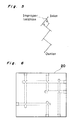
- intersection among the arranged straight holes is automatically recognized and it becomes possible to automatically detect errors in design of the cooling circuit from the directed tree diagram formulated from the inlet of the cooling circuit.
- Design in which a number of elongated straight holes A acting as water or air passages are complicatedly arranged in a block 10 of rectangular parallelopiped such as a mold, a manifold, etc. by using CAD is performed in the following sequence (1) to (3) so as to detect errors in design.
- Fig. 6 shows one example of a cooling circuit of a mold block 20, in which an improper location has been detected by the method of the present invention.
Landscapes
- Engineering & Computer Science (AREA)
- Physics & Mathematics (AREA)
- Geometry (AREA)
- Theoretical Computer Science (AREA)
- General Physics & Mathematics (AREA)
- Mathematical Analysis (AREA)
- Computational Mathematics (AREA)
- Mathematical Optimization (AREA)
- Pure & Applied Mathematics (AREA)
- Computer Hardware Design (AREA)
- Evolutionary Computation (AREA)
- General Engineering & Computer Science (AREA)
- Computer Networks & Wireless Communication (AREA)
- Moulds For Moulding Plastics Or The Like (AREA)
- Molds, Cores, And Manufacturing Methods Thereof (AREA)
Description
Claims (2)
- A method of supporting design in which a plurality of elongated straight holes (A) acting as a water or air cooling circuit are arranged in a block (10), having the form of a rectangular parallelopiped, such as a mold, manifold, etc by using computer aided design, the method comprising the steps of:arranging the straight holes (A) one by one by interactively determining a location, a direction, a diameter and a depth of each of the straigt holes (A) on a screen of a computer;formulating a directed tree diagram of the cooling circuit from an inlet of the cooling circuit through automatic recognition of intersections among the arranged straigt holes (A); andautomatically detecting the presence of a branch in said tree, having two or more forks, or an endpoint of said tree, that is not an outlet indicated by the designer, and signalling this detection to the designer as an error in the design of the cooling circuit.
- A method as claimed in claim 1, wherein the straight holes (A) include at least one through-hole (B) and at least one blind hole (C).
Applications Claiming Priority (2)
| Application Number | Priority Date | Filing Date | Title |
|---|---|---|---|
| JP2037616A JPH03240507A (en) | 1990-02-19 | 1990-02-19 | Design assisting method of mold cooling circuit |
| JP37616/90 | 1990-02-19 |
Publications (3)
| Publication Number | Publication Date |
|---|---|
| EP0443437A2 EP0443437A2 (en) | 1991-08-28 |
| EP0443437A3 EP0443437A3 (en) | 1993-11-24 |
| EP0443437B1 true EP0443437B1 (en) | 1998-05-27 |
Family
ID=12502558
Family Applications (1)
| Application Number | Title | Priority Date | Filing Date |
|---|---|---|---|
| EP91102079A Expired - Lifetime EP0443437B1 (en) | 1990-02-19 | 1991-02-14 | Method of supporting design of cooling circuit of mold |
Country Status (3)
| Country | Link |
|---|---|
| EP (1) | EP0443437B1 (en) |
| JP (1) | JPH03240507A (en) |
| DE (1) | DE69129472T2 (en) |
Cited By (1)
| Publication number | Priority date | Publication date | Assignee | Title |
|---|---|---|---|---|
| WO2013033530A1 (en) * | 2011-09-01 | 2013-03-07 | Siemens Product Lifecycle Management Software Inc. | Cooling circuit design |
Families Citing this family (3)
| Publication number | Priority date | Publication date | Assignee | Title |
|---|---|---|---|---|
| JP2585493B2 (en) * | 1991-11-08 | 1997-02-26 | 威雄 中川 | Injection mold manufacturing method using photocurable resin |
| JP7156191B2 (en) | 2019-07-11 | 2022-10-19 | トヨタ自動車株式会社 | Mold cooling circuit design method, mold manufacturing method, mold cooling circuit design device, and program |
| CN116834242B (en) * | 2023-09-01 | 2023-11-21 | 青岛海泰科模具有限公司 | Method for generating flow path line of cooling waterway of injection mold |
Family Cites Families (2)
| Publication number | Priority date | Publication date | Assignee | Title |
|---|---|---|---|---|
| US4740018A (en) * | 1982-12-28 | 1988-04-26 | Kohtaki & Co., Ltd. | Manifold and manufacturing method therefor |
| JPH0785249B2 (en) * | 1986-05-16 | 1995-09-13 | 株式会社日立製作所 | Design support device |
-
1990
- 1990-02-19 JP JP2037616A patent/JPH03240507A/en active Pending
-
1991
- 1991-02-14 DE DE69129472T patent/DE69129472T2/en not_active Expired - Fee Related
- 1991-02-14 EP EP91102079A patent/EP0443437B1/en not_active Expired - Lifetime
Cited By (1)
| Publication number | Priority date | Publication date | Assignee | Title |
|---|---|---|---|---|
| WO2013033530A1 (en) * | 2011-09-01 | 2013-03-07 | Siemens Product Lifecycle Management Software Inc. | Cooling circuit design |
Also Published As
| Publication number | Publication date |
|---|---|
| EP0443437A3 (en) | 1993-11-24 |
| DE69129472T2 (en) | 1999-02-18 |
| DE69129472D1 (en) | 1998-07-02 |
| EP0443437A2 (en) | 1991-08-28 |
| JPH03240507A (en) | 1991-10-25 |
Similar Documents
| Publication | Publication Date | Title |
|---|---|---|
| Aftosmis | Solution adaptive Cartesian grid methods for aerodynamic flows with complex geometries | |
| US5634093A (en) | Method and CAD system for designing wiring patterns using predetermined rules | |
| US4933865A (en) | Apparatus for recognition of drawn shapes or view types for automatic drawing input in CAD system | |
| US6041171A (en) | Method and apparatus for modeling material handling systems | |
| KR930003126B1 (en) | Method and system for determining the connection state of straight line short vectors displaying shapes in curve matching | |
| WO2016139979A1 (en) | Network simulation device, network simulation method, and network simulation program | |
| CN109697333A (en) | Detection method, device and the electronic equipment of pipeline detection database | |
| Oh et al. | Automated recognition of 3D pipelines from point clouds | |
| CN102707669A (en) | Method for constructing CAM (computer-aided manufacturing) system for punching for automobile girders | |
| EP0443437A2 (en) | Method of supporting design of cooling circuit of mold | |
| US7068268B2 (en) | Computer-aided product design system | |
| US20020111778A1 (en) | Methods and apparatus for electronically modeling aircraft engine harnesses | |
| JPH08263697A (en) | Method and device for creating model for finite element analysis | |
| US9710587B2 (en) | Electric-substrate electrical design apparatus using three-dimensional space, electrical design method, program and computer-readable recording medium | |
| CN104867156A (en) | Feature point identification method for pose measurement of cooperative marker | |
| KR20150024205A (en) | Apparatus and method for warning of support span error in piping design | |
| JP2884209B2 (en) | In-pipe status display method and device | |
| JP5907559B2 (en) | 3D velocity measurement system | |
| CN117641744B (en) | PCB wiring crosstalk distance determining method and device, electronic equipment and medium | |
| Dow | Integration of calculation models and CAD systems in building services design | |
| JP4826374B2 (en) | Mold design apparatus and program for mold design apparatus | |
| US6922690B2 (en) | System and method for creating a datum reference frame | |
| CN118862825B (en) | Method and system for checking external wiring based on drc | |
| KR102757455B1 (en) | Method and Device for auto-generating Water Spray Smart Plant Piping and Instrumentation Diagram and storage media storing computer program thereof | |
| JP2025000462A (en) | Plant drawing symbol detection system, plant drawing symbol detection method, and plant drawing symbol detection program |
Legal Events
| Date | Code | Title | Description |
|---|---|---|---|
| PUAI | Public reference made under article 153(3) epc to a published international application that has entered the european phase |
Free format text: ORIGINAL CODE: 0009012 |
|
| 17P | Request for examination filed |
Effective date: 19910214 |
|
| AK | Designated contracting states |
Kind code of ref document: A2 Designated state(s): DE GB |
|
| PUAL | Search report despatched |
Free format text: ORIGINAL CODE: 0009013 |
|
| AK | Designated contracting states |
Kind code of ref document: A3 Designated state(s): DE GB |
|
| 17Q | First examination report despatched |
Effective date: 19961025 |
|
| GRAG | Despatch of communication of intention to grant |
Free format text: ORIGINAL CODE: EPIDOS AGRA |
|
| GRAG | Despatch of communication of intention to grant |
Free format text: ORIGINAL CODE: EPIDOS AGRA |
|
| GRAH | Despatch of communication of intention to grant a patent |
Free format text: ORIGINAL CODE: EPIDOS IGRA |
|
| GRAH | Despatch of communication of intention to grant a patent |
Free format text: ORIGINAL CODE: EPIDOS IGRA |
|
| GRAA | (expected) grant |
Free format text: ORIGINAL CODE: 0009210 |
|
| AK | Designated contracting states |
Kind code of ref document: B1 Designated state(s): DE GB |
|
| REF | Corresponds to: |
Ref document number: 69129472 Country of ref document: DE Date of ref document: 19980702 |
|
| PLBE | No opposition filed within time limit |
Free format text: ORIGINAL CODE: 0009261 |
|
| STAA | Information on the status of an ep patent application or granted ep patent |
Free format text: STATUS: NO OPPOSITION FILED WITHIN TIME LIMIT |
|
| 26N | No opposition filed | ||
| PGFP | Annual fee paid to national office [announced via postgrant information from national office to epo] |
Ref country code: DE Payment date: 20010205 Year of fee payment: 11 |
|
| PGFP | Annual fee paid to national office [announced via postgrant information from national office to epo] |
Ref country code: GB Payment date: 20010214 Year of fee payment: 11 |
|
| REG | Reference to a national code |
Ref country code: GB Ref legal event code: IF02 |
|
| PG25 | Lapsed in a contracting state [announced via postgrant information from national office to epo] |
Ref country code: GB Free format text: LAPSE BECAUSE OF NON-PAYMENT OF DUE FEES Effective date: 20020214 |
|
| PG25 | Lapsed in a contracting state [announced via postgrant information from national office to epo] |
Ref country code: DE Free format text: LAPSE BECAUSE OF NON-PAYMENT OF DUE FEES Effective date: 20020903 |
|
| GBPC | Gb: european patent ceased through non-payment of renewal fee |
Effective date: 20020214 |