EP0442732B1 - Mailer type business form - Google Patents
Mailer type business form Download PDFInfo
- Publication number
- EP0442732B1 EP0442732B1 EP91301179A EP91301179A EP0442732B1 EP 0442732 B1 EP0442732 B1 EP 0442732B1 EP 91301179 A EP91301179 A EP 91301179A EP 91301179 A EP91301179 A EP 91301179A EP 0442732 B1 EP0442732 B1 EP 0442732B1
- Authority
- EP
- European Patent Office
- Prior art keywords
- ply
- cutout
- self
- area
- top surface
- Prior art date
- Legal status (The legal status is an assumption and is not a legal conclusion. Google has not performed a legal analysis and makes no representation as to the accuracy of the status listed.)
- Expired - Lifetime
Links
Images
Classifications
-
- B—PERFORMING OPERATIONS; TRANSPORTING
- B42—BOOKBINDING; ALBUMS; FILES; SPECIAL PRINTED MATTER
- B42D—BOOKS; BOOK COVERS; LOOSE LEAVES; PRINTED MATTER CHARACTERISED BY IDENTIFICATION OR SECURITY FEATURES; PRINTED MATTER OF SPECIAL FORMAT OR STYLE NOT OTHERWISE PROVIDED FOR; DEVICES FOR USE THEREWITH AND NOT OTHERWISE PROVIDED FOR; MOVABLE-STRIP WRITING OR READING APPARATUS
- B42D5/00—Sheets united without binding to form pads or blocks
- B42D5/02—Form sets
- B42D5/023—Continuous form sets
- B42D5/025—Mailer assemblies
- B42D5/026—Mailer assemblies with return letter or return card
Definitions
- This invention relates to mailer type business forms, also commonly known in the trade as "mailers". Under some circumstances, it is desirable to produce a mailer that does not have a "fly sheet", that is one in which the top sheet of the product offered for sale allows one to view the address information.
- a mailer that has a top sheet with a cutout therein, a transparent patch and a CB coating containing colorless dye disposed beneath the cutout, and a CF coating disposed on an underlying ply in alignment with the transparent patch.
- U.S. patent 4,729,506 a mailer is provided that has a top sheet with a cutout therein, a transparent patch and a CB coating containing colorless dye disposed beneath the cutout, and a CF coating disposed on an underlying ply in alignment with the transparent patch.
- patent 4,705,298 for the production of a mailer having the web underlying the cutout and a window patch comprises a web of self-imaging material.
- the self-imaging material is a coating of microcapsules of dye and dye developer. When impacted by an impact printer or the like, the web provides images on itself through the windows covered by the window patches.
- U.S. patent B14,425,386 a mailer is provided which includes a localized self-imaging area on the top surface therein.
- a mailer type business form which overcomes the drawbacks associated with the prior art, examples of which are discussed above.
- the business form according to the present invention has a minimum number of parts and patches, yet provides a legible address area that is not as susceptible to rupture of the dye capsules when passing through postal equipment as some of the prior art systems.
- the present invention provides a mailer type business form comprising: a top ply having a top surface and a bottom surface, and having means defining a cutout therein, said cutout having an area and position comparable to an address area on a piece of mail; a second, insert, ply underlying said top ply, including said cutout, and having a top surface in contact with the bottom surface of said top ply, and having a bottom surface a coating of self-imaging material formed on said second ply top surface; a third ply cooperating with said top ply to define an outgoing envelope, said second ply overlying said third ply; a fourth, insert, ply having a top face thereof in contact with said bottom face of said second ply; characterised in that said self-imaging material, is located only in the area of said cutout and in that said second ply has a capsule coat on the bottom, surface thereof, and said fourth ply has a resin coat on the top surface thereof aligned with
- the cutout has a generally rectangular shape with sides approximately 7.6 cms and 2.5 cms long, and the localized self-imaging material area has a generally rectangular shape with sides slightly greater in length then the cutout.
- the top ply may have a carbon spot formed on the bottom surface thereof, or where a carbon spot is not provided the top ply may have a pantograph on the top surface thereof and block out print on the bottom surface thereof.
- a fifth ply is also preferably provided between the third ply and the fourth ply, the fifth ply comprising a return envelope.
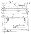
- FIGURES 1 through 3 An exemplary mailer type business form according to the invention is shown generally by reference numeral 10 in FIGURES 1 through 3.
- the business form 10 includes a top ply 11 having marginal tractor drive edges 12 and 13, and means defining a cutout 14 therein.
- the top ply 11 has a top surface 17, and a bottom surface 15.
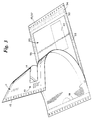
- a pantograph 16 (see FIGURE 2) is provided on the top face 17 to eliminate any possibility of show through of manifold images from underlying plies and as a precautionary measure in case of self-imaging.
- the bottom surface 15 is also provided with blockout printing 19 (see FIGURE 3) so that the underlying information cannot be read through the top ply 11.
- the cutout 14 has an area and position comparable to an address area on a piece of mail.
- the cutout 14 preferably has a generally rectangular configuration (with rounded corners in the embodiment illustrated), with a long dimension of about 7.6 cms (three inches), and a short dimension of about 2.5 cm (one inch).
- a perforation 18 adjacent tractor drive edge 12 is also provided.
- the cutout 14 is completely open, free of any material therein or covering it.
- a second, insert ply 20 Underlying the top ply 11 is a second, insert ply 20.
- the insert ply 20 underlies the top ply 11 at the area of the cutout 14, and has a top surface 21 in contact with the bottom surface 15 of the top ply 11.
- a localized coating of self-imaging material 22 is formed on the second ply top surface 21 only in the area thereof overlaid by the cutout 14.
- the self-imaging material is formed of two layers 23, 24, although it may be formed as a one pass system (such as shown on the top sheet in Chang patent 4,425,386).
- the sheet 20 When formed as a two pass system, the sheet 20 preferably is a bond sheet and the self-imaging area 22 is formed of a first layer 23 of MCP-CF with a layer 24 of MCP-CB applied over it.
- the ply 20 could be MCP-CF or MCP-CFB paper.
- the self-imaging localized coating 22 is -- in the preferred embodiment illustrated in FIGURES 1 through 3 -- also of generally rectangular configuration corresponding to the configuration of the cutout 14, only having slightly greater dimensions (e.g. a rectangular area with a length of slightly more than 7.6 cms (three inches), and a width of slightly more than 2.5 cm (one inch)).
- the second ply 20 also has a perforation 25 in alignment with the perforation 18 in the top ply 11, and terminates at an end 28. Also, it is preferred that a capsule coating (CB) 27 be provided on the bottom face 26 of the second ply 20.
- the capsule coat 27 is shown applied over the entire bottom face 20, but it could be localized and non-aligned with the self-imaging material 22 (at a position where it imparts variable data to an underlying ply or plies).
- a fourth ply 30 is provided beneath the second ply 20.
- the fourth ply 30 preferably has a marginal tractor drive end portion 31, and perforations 32 in alignment with the perforations 18, 25.
- the preferred mailer 10 also includes a fifth ply 40 having a tractor drive end portion 41 and perforations 42 in alignment with the perforations 18, 25, 32.
- the cut end 43 thereof is in alignment with the free ends 28, 35, and there is an adhesive section 44 (rewettable glue) adjacent the cut end 43.
- the ply 40 is of a two sheet construction, a bottom sheet 46 and a top sheet 47 which together form a return envelope, with adhesive 44 on a strip adapted to fold back over the envelope top sheet 47 and seal it.
- the bottom sheet 46 is slit or perfed to form cut end 43, and extends past end 43 to form a tractor feed section 45.
- a third bottom, ply 50 is also provided having tractor feed ends 51, 52.
- the third ply 50 cooperates with the top ply 11 to define an outgoing envelope.
- the second fourth, and fifth plies 20, 30, and 40 overlie the third ply 50.
- adhesive is placed along sections 53 (see FIGURE 3) of the third ply 50 to attach the top ply 11 to the bottom ply 50 to define the outgoing envelope, and adhesive 54 also is provided inside the marginal edge portions 13, 45, 52 thereof.
- FIGURES 1 through 3 While a five ply construction is illustrated for the mailer 10 in FIGURES 1 through 3, a wide variety of other constructions may also be provided. For example a four ply construction may be provided.
- a transparent window patch may be applied to cover the cutout 14. This is preferably accomplished by providing a rectangular transparent patch having dimensions greater than the dimensions of the cutout 14 and adhesively secured to the bottom face 15 of the top ply 11.
- the transparent patch will overlie the localized coating of self-imaging material 22, but not extend a significantly greater distance.
- the top ply 11 may also have a carbon spot provided on the bottom surface 15 thereof, which may overlie the capsule and resin coats 27, 33 on the underlying sheets. With the carbon spot at the area of variable printing there is no necessity for a pantograph or blockout printing on the top ply 11.
- plies may be of bond, carbonless, carbon interleaf, or other conventional paper types, having other conventional features.
- the mailer 10 in FIGURE 1 In the typical manner of utilization of the mailer 10 in FIGURE 1, which is originally in continuous form (see the connection 55 between two adjacent mailers 10 in FIGURE 2), it is fed to an impact printer where variable information is applied by impacting with a clear ribbon, or a ribbonless printer, at the cutout area 14.
- the printer stylus impacting the self-imaging material 22 causes the address to appear.
- Other portions of the mailer may be impacted by a printing stylus too, such as the portions overlying the coatings 27, 33, to impart variable information on the ply 30.
- the mailer 10 is detached along perforated line 55 from other mailers 10, and sent out through the mail.
- the self-imaging area 22 is not affected by the pressure of the equipment as much as if it were on the top sheet so therefore there is less blurring of the address information, and the address information may be more effectively optically scanned and read by humans.
- the end user detaches the end strip along the perforations 18, 25, etc. and removes the interior contents by grasping thumb notch (63, FIGURE 2) in the left hand and right edge with the right hand and "snapping" in an opposite lateral direction.
- one of the insert plies --either one or both of plies 20, 30 -- will be inserted in the return envelope comprising the fifth ply 40, adhesive 44 will be brought in contact with the top sheet 47, and the return envelope mailed back to the entity whose address is already preprinted thereon.
Landscapes
- Credit Cards Or The Like (AREA)
- Color Printing (AREA)
Applications Claiming Priority (2)
| Application Number | Priority Date | Filing Date | Title |
|---|---|---|---|
| US479704 | 1990-02-15 | ||
| US07/479,704 US5024374A (en) | 1990-02-15 | 1990-02-15 | Flyless mailer having top sheet with cutout |
Publications (2)
| Publication Number | Publication Date |
|---|---|
| EP0442732A1 EP0442732A1 (en) | 1991-08-21 |
| EP0442732B1 true EP0442732B1 (en) | 1994-12-28 |
Family
ID=23905074
Family Applications (1)
| Application Number | Title | Priority Date | Filing Date |
|---|---|---|---|
| EP91301179A Expired - Lifetime EP0442732B1 (en) | 1990-02-15 | 1991-02-13 | Mailer type business form |
Country Status (6)
| Country | Link |
|---|---|
| US (1) | US5024374A (ja) |
| EP (1) | EP0442732B1 (ja) |
| JP (1) | JPH068676A (ja) |
| AU (1) | AU633234B2 (ja) |
| CA (1) | CA2036299C (ja) |
| NZ (1) | NZ237106A (ja) |
Families Citing this family (24)
| Publication number | Priority date | Publication date | Assignee | Title |
|---|---|---|---|---|
| US5110043A (en) * | 1991-05-16 | 1992-05-05 | Moore Business Forms, Inc. | Return mailer without fly sheet |
| US5294042A (en) * | 1991-07-19 | 1994-03-15 | Giordano Dennis R | Exteriorly controlled addressing system for window mailers |
| US5154344A (en) * | 1991-10-22 | 1992-10-13 | Mark Loch | Multiple part business form and related process |
| US5232147A (en) * | 1991-10-23 | 1993-08-03 | Belknap Business Forms, Inc. | Multi-component mailer and personalizing method |
| GB9200760D0 (en) * | 1992-01-15 | 1992-03-11 | Ken Stokes Business Forms Limi | Stationery |
| US5209698A (en) * | 1992-01-30 | 1993-05-11 | Moore Business Forms, Inc. | Piggyback label with CF or self-contained coating |
| US5295906A (en) * | 1992-05-08 | 1994-03-22 | The Standard Register Company | Business form or mailer having an imagable surface |
| US5341985A (en) * | 1993-01-19 | 1994-08-30 | Moore Business Forms, Inc. | Business form assembly with integrated mailer and return envelope |
| US5984363A (en) * | 1993-05-03 | 1999-11-16 | The Standard Register Company | Business record having a thermally imagable surface |
| US5375763A (en) * | 1993-07-12 | 1994-12-27 | Moore Business Forms, Inc. | V-fold two-ply mailer |
| US5734129A (en) * | 1994-09-23 | 1998-03-31 | Belville; Daniel T. | Forms for use with handwriting capturing device |
| CA2138361C (en) * | 1994-11-04 | 1999-08-24 | Simon Christopher Turner | Two-way mailer envelope |
| US6123253A (en) * | 1998-06-08 | 2000-09-26 | The Standard Register Company | Business form or mailer with carbonless imaging |
| US6314874B1 (en) | 1999-11-19 | 2001-11-13 | Rudolph Martorella | Manual trash compactor having an adjustable arm and stabilizing blocks |
| US7549571B2 (en) * | 2002-09-18 | 2009-06-23 | Ecoenvelopes, Llc | Environmentally friendly reusable envelope structures |
| US7726548B2 (en) * | 2004-02-25 | 2010-06-01 | Ecoenvelopes, Llc | Reusable envelope structures and methods |
| US8763891B1 (en) | 2004-02-25 | 2014-07-01 | Carol A. DeLaVergne | Reusable envelope structures and methods |
| US7721943B2 (en) | 2004-09-09 | 2010-05-25 | Moore Wallace North America, Inc. | Two way electronic media mailer |
| CA2603234A1 (en) | 2005-04-05 | 2006-10-12 | Ecoenvelopes, Llc | Reusable envelope structures and methods |
| US20060266808A1 (en) * | 2005-05-26 | 2006-11-30 | Ecoenvelopes, Llc | Envelope structures and methods |
| EP2076447A4 (en) * | 2006-08-18 | 2013-07-24 | Ecoenvelopes Llc | REUSABLE ENVELOPES |
| US9617041B1 (en) * | 2009-02-19 | 2017-04-11 | Ecoenvelopes, Llc. | Conversion envelopes |
| US8875985B1 (en) | 2009-02-19 | 2014-11-04 | eco Envelopes, LLC. | Conversion envelopes |
| US9878825B1 (en) | 2015-06-02 | 2018-01-30 | Ecoenvelopes, Llc | Reusable top flap envelope with dual opposing seal flaps |
Family Cites Families (10)
| Publication number | Priority date | Publication date | Assignee | Title |
|---|---|---|---|---|
| FR2209332A5 (ja) * | 1972-11-06 | 1974-06-28 | Sapeic | |
| FR2284532A1 (fr) * | 1974-09-11 | 1976-04-09 | Nicham Robert | Liasse-enveloppe d'expedition postale livree sous forme de bande continue |
| DK226277A (da) * | 1977-02-24 | 1978-08-25 | Petits Fils De Leonard | Konvolut |
| US4172605A (en) * | 1977-05-16 | 1979-10-30 | Uarco Incorporated | Chemically reactive recording medium |
| US4425386A (en) * | 1982-07-07 | 1984-01-10 | Wallace Computer Services, Inc. | Multi-sheet assembly using autogenous coating |
| CA1185933A (en) * | 1982-08-31 | 1985-04-23 | Andre Vigneault | Mailer construction |
| IT1157996B (it) * | 1982-12-29 | 1987-02-18 | Franco Ferrando | Modulo per corrispondenza compiuterizzata |
| US4705298A (en) * | 1984-05-03 | 1987-11-10 | Moore Business Forms, Inc. | Die cut window mailer with self-imaging sheet |
| US4744508A (en) * | 1987-01-20 | 1988-05-17 | Ncr Corporation | Continuous form mailer assembly |
| US4729506A (en) * | 1987-02-04 | 1988-03-08 | Transkrit Corporation | Mailer with transparent patch |
-
1990
- 1990-02-15 US US07/479,704 patent/US5024374A/en not_active Expired - Fee Related
-
1991
- 1991-02-13 EP EP91301179A patent/EP0442732B1/en not_active Expired - Lifetime
- 1991-02-13 NZ NZ237106A patent/NZ237106A/en unknown
- 1991-02-13 CA CA002036299A patent/CA2036299C/en not_active Expired - Fee Related
- 1991-02-14 AU AU71066/91A patent/AU633234B2/en not_active Ceased
- 1991-02-15 JP JP3076001A patent/JPH068676A/ja active Pending
Also Published As
| Publication number | Publication date |
|---|---|
| AU7106691A (en) | 1991-08-22 |
| EP0442732A1 (en) | 1991-08-21 |
| CA2036299C (en) | 1997-12-30 |
| NZ237106A (en) | 1992-11-25 |
| JPH068676A (ja) | 1994-01-18 |
| AU633234B2 (en) | 1993-01-21 |
| US5024374A (en) | 1991-06-18 |
| CA2036299A1 (en) | 1991-08-16 |
Similar Documents
| Publication | Publication Date | Title |
|---|---|---|
| EP0442732B1 (en) | Mailer type business form | |
| US6386442B2 (en) | Business form or mailer with carbonless imaging | |
| CA2169046C (en) | Mailer intermediate or business form | |
| US5320387A (en) | Printable coplanar laminates and method of making same | |
| US4729506A (en) | Mailer with transparent patch | |
| US4380315A (en) | Mailer | |
| US4928874A (en) | Mailer-like business form with transparent front | |
| US20120280024A1 (en) | Double postcard pressure seal form construction | |
| US5193850A (en) | Pressure seal Z-fold with transfer tape | |
| WO2003025887B1 (en) | Partial fold printable tab product | |
| US5307989A (en) | Two way mailer with external "insert" | |
| AU628952B2 (en) | Improvements in return business forms assemblies | |
| US6092843A (en) | Pressure seal license plate decal | |
| US5370302A (en) | Two way sealer postcard | |
| US20050001021A1 (en) | Certified mailer with return receipt postcard | |
| US5076489A (en) | Multi-ply mailer form and method | |
| WO2003004284A1 (en) | Print-to mail compatible, two-way self-contained mailer | |
| US6095919A (en) | Extendible form for non-impact printer | |
| US7681780B2 (en) | Foldable postcard form having a removable label | |
| US5782691A (en) | Mailable multi-sheet business form for prevention of tenting during printing | |
| US4801074A (en) | Sealed letter | |
| US5238183A (en) | Bifold mailer with return envelope | |
| US5375763A (en) | V-fold two-ply mailer | |
| US5429298A (en) | Universal mailer | |
| CA1185933A (en) | Mailer construction |
Legal Events
| Date | Code | Title | Description |
|---|---|---|---|
| PUAI | Public reference made under article 153(3) epc to a published international application that has entered the european phase |
Free format text: ORIGINAL CODE: 0009012 |
|
| AK | Designated contracting states |
Kind code of ref document: A1 Designated state(s): GB NL |
|
| 17P | Request for examination filed |
Effective date: 19920207 |
|
| 17Q | First examination report despatched |
Effective date: 19930923 |
|
| GRAA | (expected) grant |
Free format text: ORIGINAL CODE: 0009210 |
|
| AK | Designated contracting states |
Kind code of ref document: B1 Designated state(s): GB NL |
|
| PLBE | No opposition filed within time limit |
Free format text: ORIGINAL CODE: 0009261 |
|
| STAA | Information on the status of an ep patent application or granted ep patent |
Free format text: STATUS: NO OPPOSITION FILED WITHIN TIME LIMIT |
|
| 26N | No opposition filed | ||
| PGFP | Annual fee paid to national office [announced via postgrant information from national office to epo] |
Ref country code: GB Payment date: 20000120 Year of fee payment: 10 |
|
| PGFP | Annual fee paid to national office [announced via postgrant information from national office to epo] |
Ref country code: NL Payment date: 20000125 Year of fee payment: 10 |
|
| PG25 | Lapsed in a contracting state [announced via postgrant information from national office to epo] |
Ref country code: GB Free format text: LAPSE BECAUSE OF NON-PAYMENT OF DUE FEES Effective date: 20010213 |
|
| PG25 | Lapsed in a contracting state [announced via postgrant information from national office to epo] |
Ref country code: NL Free format text: LAPSE BECAUSE OF NON-PAYMENT OF DUE FEES Effective date: 20010901 |
|
| GBPC | Gb: european patent ceased through non-payment of renewal fee |
Effective date: 20010213 |
|
| NLV4 | Nl: lapsed or anulled due to non-payment of the annual fee |
Effective date: 20010901 |