EP0442261B1 - Air/fuel injector for an internal combustion engine - Google Patents
Air/fuel injector for an internal combustion engine Download PDFInfo
- Publication number
- EP0442261B1 EP0442261B1 EP91100283A EP91100283A EP0442261B1 EP 0442261 B1 EP0442261 B1 EP 0442261B1 EP 91100283 A EP91100283 A EP 91100283A EP 91100283 A EP91100283 A EP 91100283A EP 0442261 B1 EP0442261 B1 EP 0442261B1
- Authority
- EP
- European Patent Office
- Prior art keywords
- fuel
- chamber
- air
- injector
- injection valve
- Prior art date
- Legal status (The legal status is an assumption and is not a legal conclusion. Google has not performed a legal analysis and makes no representation as to the accuracy of the status listed.)
- Expired - Lifetime
Links
Images
Classifications
-
- F—MECHANICAL ENGINEERING; LIGHTING; HEATING; WEAPONS; BLASTING
- F02—COMBUSTION ENGINES; HOT-GAS OR COMBUSTION-PRODUCT ENGINE PLANTS
- F02M—SUPPLYING COMBUSTION ENGINES IN GENERAL WITH COMBUSTIBLE MIXTURES OR CONSTITUENTS THEREOF
- F02M51/00—Fuel-injection apparatus characterised by being operated electrically
- F02M51/06—Injectors peculiar thereto with means directly operating the valve needle
- F02M51/061—Injectors peculiar thereto with means directly operating the valve needle using electromagnetic operating means
- F02M51/0625—Injectors peculiar thereto with means directly operating the valve needle using electromagnetic operating means characterised by arrangement of mobile armatures
- F02M51/0635—Injectors peculiar thereto with means directly operating the valve needle using electromagnetic operating means characterised by arrangement of mobile armatures having a plate-shaped or undulated armature not entering the winding
- F02M51/0642—Injectors peculiar thereto with means directly operating the valve needle using electromagnetic operating means characterised by arrangement of mobile armatures having a plate-shaped or undulated armature not entering the winding the armature having a valve attached thereto
- F02M51/0653—Injectors peculiar thereto with means directly operating the valve needle using electromagnetic operating means characterised by arrangement of mobile armatures having a plate-shaped or undulated armature not entering the winding the armature having a valve attached thereto the valve being an elongated body, e.g. a needle valve
-
- F—MECHANICAL ENGINEERING; LIGHTING; HEATING; WEAPONS; BLASTING
- F02—COMBUSTION ENGINES; HOT-GAS OR COMBUSTION-PRODUCT ENGINE PLANTS
- F02M—SUPPLYING COMBUSTION ENGINES IN GENERAL WITH COMBUSTIBLE MIXTURES OR CONSTITUENTS THEREOF
- F02M61/00—Fuel-injectors not provided for in groups F02M39/00 - F02M57/00 or F02M67/00
- F02M61/04—Fuel-injectors not provided for in groups F02M39/00 - F02M57/00 or F02M67/00 having valves, e.g. having a plurality of valves in series
- F02M61/08—Fuel-injectors not provided for in groups F02M39/00 - F02M57/00 or F02M67/00 having valves, e.g. having a plurality of valves in series the valves opening in direction of fuel flow
-
- F—MECHANICAL ENGINEERING; LIGHTING; HEATING; WEAPONS; BLASTING
- F02—COMBUSTION ENGINES; HOT-GAS OR COMBUSTION-PRODUCT ENGINE PLANTS
- F02M—SUPPLYING COMBUSTION ENGINES IN GENERAL WITH COMBUSTIBLE MIXTURES OR CONSTITUENTS THEREOF
- F02M67/00—Apparatus in which fuel-injection is effected by means of high-pressure gas, the gas carrying the fuel into working cylinders of the engine, e.g. air-injection type
- F02M67/02—Apparatus in which fuel-injection is effected by means of high-pressure gas, the gas carrying the fuel into working cylinders of the engine, e.g. air-injection type the gas being compressed air, e.g. compressed in pumps
-
- F—MECHANICAL ENGINEERING; LIGHTING; HEATING; WEAPONS; BLASTING
- F02—COMBUSTION ENGINES; HOT-GAS OR COMBUSTION-PRODUCT ENGINE PLANTS
- F02M—SUPPLYING COMBUSTION ENGINES IN GENERAL WITH COMBUSTIBLE MIXTURES OR CONSTITUENTS THEREOF
- F02M67/00—Apparatus in which fuel-injection is effected by means of high-pressure gas, the gas carrying the fuel into working cylinders of the engine, e.g. air-injection type
- F02M67/10—Injectors peculiar thereto, e.g. valve less type
- F02M67/12—Injectors peculiar thereto, e.g. valve less type having valves
-
- F—MECHANICAL ENGINEERING; LIGHTING; HEATING; WEAPONS; BLASTING
- F02—COMBUSTION ENGINES; HOT-GAS OR COMBUSTION-PRODUCT ENGINE PLANTS
- F02M—SUPPLYING COMBUSTION ENGINES IN GENERAL WITH COMBUSTIBLE MIXTURES OR CONSTITUENTS THEREOF
- F02M69/00—Low-pressure fuel-injection apparatus ; Apparatus with both continuous and intermittent injection; Apparatus injecting different types of fuel
- F02M69/08—Low-pressure fuel-injection apparatus ; Apparatus with both continuous and intermittent injection; Apparatus injecting different types of fuel characterised by the fuel being carried by compressed air into main stream of combustion-air
-
- F—MECHANICAL ENGINEERING; LIGHTING; HEATING; WEAPONS; BLASTING
- F02—COMBUSTION ENGINES; HOT-GAS OR COMBUSTION-PRODUCT ENGINE PLANTS
- F02B—INTERNAL-COMBUSTION PISTON ENGINES; COMBUSTION ENGINES IN GENERAL
- F02B75/00—Other engines
- F02B75/02—Engines characterised by their cycles, e.g. six-stroke
- F02B2075/022—Engines characterised by their cycles, e.g. six-stroke having less than six strokes per cycle
- F02B2075/025—Engines characterised by their cycles, e.g. six-stroke having less than six strokes per cycle two
Definitions
- This invention relates to a fuel injection type engine and more particularly to an improved air/fuel injector for an internal combustion engine.
- One type of fuel injector which is advantageous in connection with two cycle internal combustion engine is an injector of the air/fuel type.
- injector in addition to fuel, pressurized air is injected into the combustion chamber of the engine when the injector valve is opened.
- this type of device has particular advantages, there are some disadvantages with the previously proposed injectors of this type.
- one type of injector has the fuel delivered to the injector in the area where the injector valve opens and closes. The air flow across the injector outlet when the injector valve is opened creates a vacuum which assist in the delivery of fuel.
- the amount of vacuum produced will vary in relation to the lift of the valve and also during the opening and closing of the valve when the opening area varies.
- the fuel delivery to the engine can become unstable and erratic.
- the variable lift will give further rise to differences in the amount of fuel injected.
- a fuel/air injector for injecting fuel into the combustion chamber of an internal combustion engine according to the preamble of claim 1 is known from EP-A-0 189 714.
- This known air/fuel injector shows an injection valve, having a cylindrical stem, which is arranged in a cylindrical chamber. An insert is introduced into this cylindrical chamber, being co-axially arranged with the valve stem and forming a venturi section. Means are provided for delivering fuel under pressure to said chamber at the area of low air pressure of the venturi chamber.
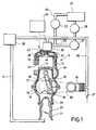
- Figure 1 is a partially schematic cross sectional view taken along through a single cylinder of a two-cycle crankcase compression internal combustion engine having a fuel/air injection system constructed in accordance with embodiments of the invention, with certain of the auxiliary components being shown schematically.
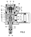
- Figure 2 is an enlarged cross sectional view taken through the air/fuel injector.
- a single cylinder of a three cylinder two-cycle crankcase compression internal combustion engine having a fuel/air injection unit constructed in accordance with an embodiment of the invention is identified generally by the reference numeral 11. Only a single cylinder of the engine 11 is depicted because it is believed that those skilled in the art can readily understand how the invention can be employed in connection with multiple cylinder engines. Also, although the invention is described in conjunction with a reciprocating engine, the invention can be equally as well practiced with other types of engines and also engines that operate on other than the crankcase compression principal. However, the invention does have particular utility in conjunction with two-cycle engines.
- the engine 11 includes a cylinder block 12 formed with a cylinder bore 13 in which a piston 14 reciprocates.
- the piston 14 is connected by means of a connecting rod 15 to a throw 16 of a crankshaft, indicated at 17, for driving the crankshaft in a known manner.
- the crankshaft 17 is rotatably journaled within a crankcase chamber 18 that is formed by the cylinder block 12 and a crankcase 19 that is affixed to the cylinder block in any suitable manner.
- An air charge is delivered to the crankcase chamber 18 through an intake manifold 21 in which a flow controlling throttle valve 22 is positioned.
- a reed type check valve 23 is interposed between the intake manifold 21 and the crankcase chamber 18 so as to preclude reverse flow, as is well known in this art.
- the charge which has been admitted to the crankcase chamber 18 will be compressed during downward movement of the piston 14 and then is transferred to the combustion chamber through one or more scavenge ports 24.
- a cylinder head 25 is affixed to the cylinder block 12 and supports a fuel/air injection unit, indicated generally by the reference numeral 26.
- the construction of the fuel/air injection unit 26 will be described later.
- Fuel is supplied to the fuel/air injection unit 26 from a remotely positioned fuel tank 27 by means of a fuel pump 28 and conduit 29.
- a fuel filter 31 is provided in this conduit 29 and filters the fuel delivered to the fuel/air injection unit 26.
- a pressure relief valve 32 is positioned in a return conduit 33 that leads back to the fuel tank 27 and which maintains a uniform head of fuel in the fuel/air injector unit 26 by bypassing excess fuel back to the tank 27.
- Compressed air is delivered to the fuel/air injection unit 26 from an air compressor 34.
- the air compressor 34 is driven by means of a belt 35 from a pulley 36 that is affixed to the crankshaft 17 for rotation with it.
- the compressor 34 draws air from the atmosphere through an inlet 37 and delivers it to the fuel/air injection unit 26 by means of a supply conduit 38.
- the air pressure is regulated by a pressure regulator and accumulator 39 which regulates the air pressure by returning excess air to the induction manifold 21 through a bypass conduit 41.
- a spark plug 42 is provided in the cylinder head 26 for firing the fuel/air charge generated both by the injector unit 26 and the induction system already described. The burnt fuel/air charge is then discharged to the atmosphere through an exhaust port 43.
- the fuel/air injector 26 injects fuel into a combustion chamber 44 formed in part by a recess in the cylinder head 25 through a delivery passage 45.
- the fuel/air injector 26 and spark plug 42 are controlled by a control unit, indicated generally by the reference numeral 46.
- the control unit 46 may operate on any desired strategy. However, basically the strategy is such that the injection valve is opened and fuel of the fuel/air injector 26 is then delivered.
- the construction of one type of fuel/air injector is shown in Figure 2 and will now be described by reference to that figure.
- the fuel/air injector 26 is comprised of an outer housing assembly, indicated generally be the reference numeral 47 and which mounts a fuel injector, 48 which is supplied with fuel from the system described previously including the inlet conduit 29 and an air injector portion, indicated generally by the reference numeral 49 and which supplies air from an air port 50 that is communicated with the conduit 38.
- the housing assembly 47 has a pilot portion 51 which extends into the delivery passage 45 of the cylinder head and which defines a valve seat 52 that is opened and closed by a head portion 53 of an injection valve, indicated generally by the reference numeral 54.
- the injection valve 54 extends through the pilot portion 51 with a clearance therebetween which defines a chamber 55 to which air is delivered under pressure from the port 50.
- the injection valve 54 has affixed to its upper end an armature plate 56 by means of a nut 57 so as to provide an axial adjustment for the armature plate 56 on the injection valve 54 to control the maximum lift of the valve head 53.
- a solenoid winding 58 encircles the stem of the valve 54 and is energized through a conductor 59 from the controller 46.
- a coil compression spring 61 acts against a cup-shape member 62 that is held axially to the stem of the injection valve 54 against the armature plate 56.
- the opposite end of the spring 61 reacts against the housing 47 so as to bold the injection valve 54 in its closed position until the solenoid 58 is energized.
- the solenoid 58 When the solenoid 58 is energized, the armature plate 56 will move downwardly until it contacts a stop plate 63 which sets the maximum opening area for the injector valve 54 and air under pressure can then be discharged.
- the fuel injector 48 is mounted so that its nozzle portion 64 extends perpendicularly to the chamber 56.
- the nozzle portion 64 communicates with a restricted annular recess 65 formed between a sleeve 66 mounted within the housing assembly 47 and an enlarged cylindrical portion 67 formed on the stem of the injector valve 54.
- the injector nozzle 64 communicates with the annular recess 65 through one or more radially extending ports 68 formed in the sleeve 66.
- the cross sectional area of the passageway 65 regardless of the axial position of the injection valve 54 is less than the maximum cross sectional flow area provided by the valve head 53 and the seat 52 when the valve head 53 is it fully opened position.
- the amount of fuel discharged will always be into a substantially constant vacuum and will not be dependent upon the degree of valve lift. As a result, more uniform fuel delivery will be possible.
- the injector 48 injects into an area that is a lower pressure than the pressure of air in the chamber 55 a lower pressure fuel injector can be employed so as to avoid leakage and cost problems.
Description
- This invention relates to a fuel injection type engine and more particularly to an improved air/fuel injector for an internal combustion engine.
- One type of fuel injector which is advantageous in connection with two cycle internal combustion engine is an injector of the air/fuel type. With this type of injector, in addition to fuel, pressurized air is injected into the combustion chamber of the engine when the injector valve is opened. Although this type of device has particular advantages, there are some disadvantages with the previously proposed injectors of this type. For example, one type of injector has the fuel delivered to the injector in the area where the injector valve opens and closes. The air flow across the injector outlet when the injector valve is opened creates a vacuum which assist in the delivery of fuel. However, the amount of vacuum produced will vary in relation to the lift of the valve and also during the opening and closing of the valve when the opening area varies. As a result, the fuel delivery to the engine can become unstable and erratic. In addition, it is often desirable to change the amount of lift of the valve during engine running to accommodate changes in engine performance. Of course, the variable lift will give further rise to differences in the amount of fuel injected.
- These problems can be avoided to some extent if the fuel is injected in an area other than the area of the injection valve and its seat. However, when this is done the fuel must be injected into a high pressure area and hence the fuel pressure must be greater than the air pressure. This gives rise to the cost of higher pressure fuel injectors and also increases the likelihood of leakage in the system due to the higher pressure of fuel.
- A fuel/air injector for injecting fuel into the combustion chamber of an internal combustion engine according to the preamble of claim 1 is known from EP-A-0 189 714.
- This known air/fuel injector shows an injection valve, having a cylindrical stem, which is arranged in a cylindrical chamber. An insert is introduced into this cylindrical chamber, being co-axially arranged with the valve stem and forming a venturi section. Means are provided for delivering fuel under pressure to said chamber at the area of low air pressure of the venturi chamber.
- It is the object of the present invention to provide an improved air/fuel injector for an internal combustion engine.
- This object is solved according to the invention by the subject matter of claim 1.
- Preferred embodiments of the invention are subject matter of the sub-claims.
- Figure 1 is a partially schematic cross sectional view taken along through a single cylinder of a two-cycle crankcase compression internal combustion engine having a fuel/air injection system constructed in accordance with embodiments of the invention, with certain of the auxiliary components being shown schematically.
- Figure 2 is an enlarged cross sectional view taken through the air/fuel injector.
- Referring first to Figure 1, a single cylinder of a three cylinder two-cycle crankcase compression internal combustion engine having a fuel/air injection unit constructed in accordance with an embodiment of the invention is identified generally by the
reference numeral 11. Only a single cylinder of theengine 11 is depicted because it is believed that those skilled in the art can readily understand how the invention can be employed in connection with multiple cylinder engines. Also, although the invention is described in conjunction with a reciprocating engine, the invention can be equally as well practiced with other types of engines and also engines that operate on other than the crankcase compression principal. However, the invention does have particular utility in conjunction with two-cycle engines. - The
engine 11 includes acylinder block 12 formed with acylinder bore 13 in which apiston 14 reciprocates. Thepiston 14 is connected by means of a connectingrod 15 to athrow 16 of a crankshaft, indicated at 17, for driving the crankshaft in a known manner. - The
crankshaft 17 is rotatably journaled within acrankcase chamber 18 that is formed by thecylinder block 12 and acrankcase 19 that is affixed to the cylinder block in any suitable manner. An air charge is delivered to thecrankcase chamber 18 through anintake manifold 21 in which a flow controllingthrottle valve 22 is positioned. A reedtype check valve 23 is interposed between theintake manifold 21 and thecrankcase chamber 18 so as to preclude reverse flow, as is well known in this art. The charge which has been admitted to thecrankcase chamber 18 will be compressed during downward movement of thepiston 14 and then is transferred to the combustion chamber through one ormore scavenge ports 24. - A
cylinder head 25 is affixed to thecylinder block 12 and supports a fuel/air injection unit, indicated generally by thereference numeral 26. The construction of the fuel/air injection unit 26 will be described later. - Fuel is supplied to the fuel/
air injection unit 26 from a remotely positionedfuel tank 27 by means of afuel pump 28 andconduit 29. Afuel filter 31 is provided in thisconduit 29 and filters the fuel delivered to the fuel/air injection unit 26. Apressure relief valve 32 is positioned in areturn conduit 33 that leads back to thefuel tank 27 and which maintains a uniform head of fuel in the fuel/air injector unit 26 by bypassing excess fuel back to thetank 27. - Compressed air is delivered to the fuel/
air injection unit 26 from anair compressor 34. Theair compressor 34 is driven by means of abelt 35 from apulley 36 that is affixed to thecrankshaft 17 for rotation with it. Thecompressor 34 draws air from the atmosphere through aninlet 37 and delivers it to the fuel/air injection unit 26 by means of asupply conduit 38. The air pressure is regulated by a pressure regulator andaccumulator 39 which regulates the air pressure by returning excess air to theinduction manifold 21 through abypass conduit 41. - A
spark plug 42 is provided in thecylinder head 26 for firing the fuel/air charge generated both by theinjector unit 26 and the induction system already described. The burnt fuel/air charge is then discharged to the atmosphere through anexhaust port 43. - The fuel/
air injector 26 injects fuel into acombustion chamber 44 formed in part by a recess in thecylinder head 25 through adelivery passage 45. The fuel/air injector 26 andspark plug 42 are controlled by a control unit, indicated generally by thereference numeral 46. Thecontrol unit 46 may operate on any desired strategy. However, basically the strategy is such that the injection valve is opened and fuel of the fuel/air injector 26 is then delivered. - The construction of one type of fuel/air injector is shown in Figure 2 and will now be described by reference to that figure. The fuel/
air injector 26 is comprised of an outer housing assembly, indicated generally be thereference numeral 47 and which mounts a fuel injector, 48 which is supplied with fuel from the system described previously including theinlet conduit 29 and an air injector portion, indicated generally by thereference numeral 49 and which supplies air from anair port 50 that is communicated with theconduit 38. - The
housing assembly 47 has apilot portion 51 which extends into thedelivery passage 45 of the cylinder head and which defines avalve seat 52 that is opened and closed by ahead portion 53 of an injection valve, indicated generally by thereference numeral 54. Theinjection valve 54 extends through thepilot portion 51 with a clearance therebetween which defines achamber 55 to which air is delivered under pressure from theport 50. - The
injection valve 54 has affixed to its upper end anarmature plate 56 by means of anut 57 so as to provide an axial adjustment for thearmature plate 56 on theinjection valve 54 to control the maximum lift of thevalve head 53. - A solenoid winding 58 encircles the stem of the
valve 54 and is energized through aconductor 59 from thecontroller 46. - A
coil compression spring 61 acts against a cup-shape member 62 that is held axially to the stem of theinjection valve 54 against thearmature plate 56. The opposite end of thespring 61 reacts against thehousing 47 so as to bold theinjection valve 54 in its closed position until thesolenoid 58 is energized. When thesolenoid 58 is energized, thearmature plate 56 will move downwardly until it contacts astop plate 63 which sets the maximum opening area for theinjector valve 54 and air under pressure can then be discharged. - In accordance with an important feature of the invention, the
fuel injector 48 is mounted so that itsnozzle portion 64 extends perpendicularly to thechamber 56. However, thenozzle portion 64 communicates with a restrictedannular recess 65 formed between asleeve 66 mounted within thehousing assembly 47 and an enlargedcylindrical portion 67 formed on the stem of theinjector valve 54. Theinjector nozzle 64 communicates with theannular recess 65 through one or more radially extendingports 68 formed in thesleeve 66. - In accordance with the invention, the cross sectional area of the
passageway 65, regardless of the axial position of theinjection valve 54 is less than the maximum cross sectional flow area provided by thevalve head 53 and theseat 52 when thevalve head 53 is it fully opened position. As a result of this difference in cross sectional area, the amount of fuel discharged will always be into a substantially constant vacuum and will not be dependent upon the degree of valve lift. As a result, more uniform fuel delivery will be possible. In addition, since theinjector 48 injects into an area that is a lower pressure than the pressure of air in the chamber 55 a lower pressure fuel injector can be employed so as to avoid leakage and cost problems.
Claims (4)
- A fuel air injector (26) for injecting fuel into the combustion chamber of an internal combustion engine, comprising :
an injection valve (54),
a chamber (55) comprising:
an outlet chamber adapted to communicate with the engine combustion chamber (44) when said injection valve (54) opens,
an inlet chamber connected with an air pressure source (34),
a venturi section arranged between said outlet chamber and said inlet chamber upstream of a seat of said injection valve,
means for delivering fuel under pressure to said chamber (55) at the venturi section at an area of lower air pressure than the air pressure in said chamber,
characterized in that
said venturi section is formed by an enlargement (67) on a stem of the injection valve (54) that passes through said chamber (55). - A fuel/air injector as set forth in claim 1 wherein the venturi section is co-axially disposed within the chamber (55).
- A fuel/air injector as set forth in claim 1 wherein the fuel is injected in a perpendicular direction to the venturi section and into the chamber (55).
- A fuel/air injector as set forth in claim 1 wherein the low pressure area is defined by an area having an effective cross sectional flow area that is less than the effective cross sectional area of the injection valve (54) when the injection valve is at maximum lift.
Applications Claiming Priority (2)
| Application Number | Priority Date | Filing Date | Title |
|---|---|---|---|
| JP2002985A JP2761422B2 (en) | 1990-01-10 | 1990-01-10 | Fuel injection engine |
| JP2985/90 | 1990-01-10 |
Publications (2)
| Publication Number | Publication Date |
|---|---|
| EP0442261A1 EP0442261A1 (en) | 1991-08-21 |
| EP0442261B1 true EP0442261B1 (en) | 1994-06-15 |
Family
ID=11544664
Family Applications (1)
| Application Number | Title | Priority Date | Filing Date |
|---|---|---|---|
| EP91100283A Expired - Lifetime EP0442261B1 (en) | 1990-01-10 | 1991-01-10 | Air/fuel injector for an internal combustion engine |
Country Status (4)
| Country | Link |
|---|---|
| US (1) | US5131375A (en) |
| EP (1) | EP0442261B1 (en) |
| JP (1) | JP2761422B2 (en) |
| DE (1) | DE69102445T2 (en) |
Families Citing this family (5)
| Publication number | Priority date | Publication date | Assignee | Title |
|---|---|---|---|---|
| IT1248314B (en) * | 1991-05-20 | 1995-01-05 | Piaggio Veicoli Europ | HEAD FOR C.I. WITH DEVICE FOR PNEUMATICALLY ASSISTED DIRECT FUEL INJECTION |
| EP0769611A1 (en) * | 1995-09-22 | 1997-04-23 | Bernd Scheffel | Apparatus for intermittently atomizing and injecting fuel |
| AUPP802299A0 (en) * | 1999-01-05 | 1999-01-28 | Split Cycle Technology Limited | A method and means for providing a combustible mixture |
| US6626161B2 (en) * | 2001-12-13 | 2003-09-30 | Synerject, Llc | Methods and assemblies for delivering fuel and gas in air assist fuel injection systems |
| CA2770415C (en) * | 2009-08-27 | 2012-08-28 | Mcalister Technologies, Llc | Fuel injector actuator assemblies and associated methods of use and manufacture |
Family Cites Families (11)
| Publication number | Priority date | Publication date | Assignee | Title |
|---|---|---|---|---|
| US4508091A (en) * | 1979-10-26 | 1985-04-02 | Colt Industries Operating Corp | Fuel metering apparatus with multi-stage fuel metering valve assembly |
| US4569484A (en) * | 1984-08-31 | 1986-02-11 | The United States Of America As Represented By The United States Department Of Energy | Air blast type coal slurry fuel injector |
| FR2575521B1 (en) * | 1984-12-28 | 1989-04-07 | Inst Francais Du Petrole | DEVICE FOR IMPROVING THE QUALITY OF THE FUEL MIXTURE DELIVERED BY A PNEUMATIC INJECTION SYSTEM |
| DE3650025T2 (en) * | 1985-10-11 | 1994-12-01 | Orbital Eng Australia | DIFFERENTIAL PRESSURE FUEL AIR GAUGE. |
| BE903515A (en) * | 1985-10-24 | 1986-02-17 | Orbital Eng Pty | DOSE SUPPLY OF FUEL TO AN ENGINE AND APPARATUS THEREFOR. |
| DE3808671A1 (en) * | 1987-03-13 | 1988-09-22 | Orbital Eng Pty | DEVICE AND METHOD FOR INJECTING FUEL |
| CA1306394C (en) * | 1987-04-15 | 1992-08-18 | Peter William Ragg | Direct fuel injection systems |
| US4834291A (en) * | 1987-11-19 | 1989-05-30 | Brunswick Corporation | Fuel injector |
| JP2602710B2 (en) * | 1988-03-01 | 1997-04-23 | トヨタ自動車株式会社 | Fuel injection device for internal combustion engine |
| US4938417A (en) * | 1989-04-12 | 1990-07-03 | Fuel Systems Textron Inc. | Airblast fuel injector with tubular metering valve |
| US4987878A (en) * | 1989-06-21 | 1991-01-29 | Johnson Jerome V | Fuel injection system |
-
1990
- 1990-01-10 JP JP2002985A patent/JP2761422B2/en not_active Expired - Fee Related
-
1991
- 1991-01-09 US US07/639,357 patent/US5131375A/en not_active Expired - Lifetime
- 1991-01-10 DE DE69102445T patent/DE69102445T2/en not_active Expired - Fee Related
- 1991-01-10 EP EP91100283A patent/EP0442261B1/en not_active Expired - Lifetime
Also Published As
| Publication number | Publication date |
|---|---|
| EP0442261A1 (en) | 1991-08-21 |
| DE69102445D1 (en) | 1994-07-21 |
| JPH03210063A (en) | 1991-09-13 |
| JP2761422B2 (en) | 1998-06-04 |
| US5131375A (en) | 1992-07-21 |
| DE69102445T2 (en) | 1994-10-06 |
Similar Documents
| Publication | Publication Date | Title |
|---|---|---|
| US5069189A (en) | Fuel injector system for internal combustion engine | |
| US5884606A (en) | System for generating high fuel pressure for a fuel injection system used in internal combustion engines | |
| EP0315328B1 (en) | Pneumatic direct cylinder fuel injection system | |
| US4798186A (en) | Fuel injector unit | |
| US5423484A (en) | Injection rate shaping control ported barrel for a fuel injection system | |
| US5048497A (en) | Fuel injection unit | |
| US5113829A (en) | Two cycle internal combustion engine | |
| US5063886A (en) | Two-stroke engine | |
| US5062396A (en) | Device and method for introducing a carburetted mixture under presssure into the cylinder of an engine | |
| US5487508A (en) | Injection rate shaping control ported check stop for a fuel injection nozzle | |
| JP2696446B2 (en) | In-cylinder direct injection type injection valve assist air supply device | |
| JP3326173B2 (en) | Internal combustion engine with compressor function | |
| US5560825A (en) | Edge filter for a high pressure hydraulic system | |
| US7891338B2 (en) | Device for regulating pressure/flow in an internal combustion engine fuel injection system | |
| KR20010072735A (en) | Fuel injection system control method | |
| US5239970A (en) | Fuel injection type engine | |
| US5150684A (en) | High pressure fuel injection unit for engine | |
| EP0442261B1 (en) | Air/fuel injector for an internal combustion engine | |
| US4150651A (en) | Fuel system for internal combustion engine | |
| US5398654A (en) | Fuel injection system for internal combustion engines | |
| US5479899A (en) | Fuel management system | |
| JPH0146709B2 (en) | ||
| GB1045925A (en) | Fuel supply system for compression ignition internal combustion engines | |
| EP0421356A1 (en) | Fuel injection system for an engine | |
| GB2067661A (en) | Fuel supply system for internal combustion engine |
Legal Events
| Date | Code | Title | Description |
|---|---|---|---|
| PUAI | Public reference made under article 153(3) epc to a published international application that has entered the european phase |
Free format text: ORIGINAL CODE: 0009012 |
|
| AK | Designated contracting states |
Kind code of ref document: A1 Designated state(s): DE FR GB |
|
| 17P | Request for examination filed |
Effective date: 19911015 |
|
| 17Q | First examination report despatched |
Effective date: 19920413 |
|
| GRAA | (expected) grant |
Free format text: ORIGINAL CODE: 0009210 |
|
| AK | Designated contracting states |
Kind code of ref document: B1 Designated state(s): DE FR GB |
|
| REF | Corresponds to: |
Ref document number: 69102445 Country of ref document: DE Date of ref document: 19940721 |
|
| ET | Fr: translation filed | ||
| PLBE | No opposition filed within time limit |
Free format text: ORIGINAL CODE: 0009261 |
|
| STAA | Information on the status of an ep patent application or granted ep patent |
Free format text: STATUS: NO OPPOSITION FILED WITHIN TIME LIMIT |
|
| 26N | No opposition filed | ||
| REG | Reference to a national code |
Ref country code: GB Ref legal event code: IF02 |
|
| PGFP | Annual fee paid to national office [announced via postgrant information from national office to epo] |
Ref country code: GB Payment date: 20040107 Year of fee payment: 14 |
|
| PGFP | Annual fee paid to national office [announced via postgrant information from national office to epo] |
Ref country code: FR Payment date: 20040108 Year of fee payment: 14 |
|
| PG25 | Lapsed in a contracting state [announced via postgrant information from national office to epo] |
Ref country code: GB Free format text: LAPSE BECAUSE OF NON-PAYMENT OF DUE FEES Effective date: 20050110 |
|
| GBPC | Gb: european patent ceased through non-payment of renewal fee |
Effective date: 20050110 |
|
| PG25 | Lapsed in a contracting state [announced via postgrant information from national office to epo] |
Ref country code: FR Free format text: LAPSE BECAUSE OF NON-PAYMENT OF DUE FEES Effective date: 20050930 |
|
| REG | Reference to a national code |
Ref country code: FR Ref legal event code: ST |
|
| PGFP | Annual fee paid to national office [announced via postgrant information from national office to epo] |
Ref country code: DE Payment date: 20090108 Year of fee payment: 19 |
|
| PG25 | Lapsed in a contracting state [announced via postgrant information from national office to epo] |
Ref country code: DE Free format text: LAPSE BECAUSE OF NON-PAYMENT OF DUE FEES Effective date: 20100803 |