EP0442242B1 - Method for making knotless bead bundle, a bead bundle made thereby and a tire incorporating said bead bundle - Google Patents
Method for making knotless bead bundle, a bead bundle made thereby and a tire incorporating said bead bundle Download PDFInfo
- Publication number
- EP0442242B1 EP0442242B1 EP90630216A EP90630216A EP0442242B1 EP 0442242 B1 EP0442242 B1 EP 0442242B1 EP 90630216 A EP90630216 A EP 90630216A EP 90630216 A EP90630216 A EP 90630216A EP 0442242 B1 EP0442242 B1 EP 0442242B1
- Authority
- EP
- European Patent Office
- Prior art keywords
- wrapping material
- bead
- annular turns
- tire
- wire
- Prior art date
- Legal status (The legal status is an assumption and is not a legal conclusion. Google has not performed a legal analysis and makes no representation as to the accuracy of the status listed.)
- Expired - Lifetime
Links
Images


Classifications
-
- B—PERFORMING OPERATIONS; TRANSPORTING
- B29—WORKING OF PLASTICS; WORKING OF SUBSTANCES IN A PLASTIC STATE IN GENERAL
- B29D—PRODUCING PARTICULAR ARTICLES FROM PLASTICS OR FROM SUBSTANCES IN A PLASTIC STATE
- B29D30/00—Producing pneumatic or solid tyres or parts thereof
- B29D30/06—Pneumatic tyres or parts thereof (e.g. produced by casting, moulding, compression moulding, injection moulding, centrifugal casting)
- B29D30/48—Bead-rings or bead-cores; Treatment thereof prior to building the tyre
- B29D2030/483—Treating the bead cores to increase rubber adhesion
Definitions
- the invention relates to a bead bundle intended for use in pneumatic tires, a method of making such a bead bundle, and pneumatic tires incorporating such a bead bundle.
- a bead ring provides reinforcement in the tire where the tire meets the rim.
- the bead ring is often made in the form of a bead bundle which comprises at least one (preferably one) strand of wire disposed in a plurality of adjacent annular turns which are wrapped with wire or another suitable material to hold the ends of the wire and the annular turns together.
- the ends of the wire or other wrapping material are ordinarily tucked under one of the wraps or knotted to retain the wrapping material on the bead bundle.
- the exposed ends of the wire can sometimes, over time, cause a fault or tear to develop in the bead area of the tire, limiting the life of the tire.
- the knot used to secure the wrap can cause an imbalance in the weight distribution and gauge of the bead bundle and jeopardize the uniformity of a tire in which it is used.
- the ends of the knot may trap air in the area of the bead bundle during the building of a tire which may cause eventual delamination of the bead in the tire construction. Such defects are detectable on inspection, and such tires have to be scrapped.
- bead bundle undergoes a deformation. It is believed that this bead deformation takes place when a tire construction is cured. Though not seriously detrimental to the operation of the tire, bead deformation substantially obviates the ability of the tire manufacturer to design an optimal bead shape and retain the optimized bead shape in an actual tire construction.
- US-A- 1 763 179 describes a tire bead reinforcement comprising a tension member wound into an annulus, the turns or loops being held together by a retaining strand spirally wound about the same, said strand being given extra close turns at one of the ends of the tension member to keep it from sticking out tangentially from the annulus.
- a method for making a knotless bead bundle comprises the steps of disposing at least one wire strand in a plurality of adjacent annular turns; attaching a flexible wrapping material to the annular turns by contacting a first end of the wrapping material with the annular turns and forming a loose loop of wrapping material using a portion of wrapping material adjacent to said first end and securing said loop by wrapping additional wrapping material around said portion of wrapping material in several close wraps, leaving the first end free to hold the loop and first free end in place; wrapping the annular turns with the wrapping material continuously from the loop around the annular turns and back to the loop; passing the wrapping material through the loop; and pulling the first end of the wrapping material to close the loop and to pull the wrapping material under the several close wraps adjacent to the loop.
- additional areas of close wraps may be provided at evenly spaced locations on the annular turns of wire.
- the loop may be placed on a hook or other holding means in the method to maintain the loop while the wrapping of the annular turns of wire is completed.
- the wrapping material is preferably a flexible material having good tensile strength and may be selected from the group comprising nylon cord, polyester cord, carbon fiber filaments, polyaromatic amide cord and wire. It is desirable that the wrapping material be coated with an adhesive which is compatible with rubber to ensure good adhesion of the wrapping material to the tire.
- close wraps refers to turns of wrapping material which are laid down substantially side-by-side on a bead ring
- widely spaced wraps refers to widely separated turns of wrapping material which are laid down on a bead ring
- tie down area refers to close wraps which are used specifically to secure the ends of a bead wire which is disposed in a plurality of annular turns.
- Fig. 1 illustrates a bead bundle made according to the invention.
- Fig. 2 illustrates an enlarged isolated view of the tie down area of the wrapping material on a bead bundle including the first end, the loop, and the second end of the wrapping material.
- Fig. 2a illustrates the method step where the first end is pulled to tighten the loop.
- Fig. 2b illustrates method step where the wrapping material is pulled under the close wrap and the ends have been cut flush with the surface of the bead bundle.
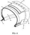
- Fig. 3 illustrates a tire of the invention made using the bead bundle of the invention.
- bead bundle 10 comprises a single strand of wire 11 which is wound in a plurality of adjacent annular turns to comprise a ring having a number of layers of wire.
- the annular turns of wire are held together by tightly wrapped wrapping material 13 which also serves to hold down ends 38 and 40 of the wire.
- ends 38 and 40 will be in close proximity to one another on the ring so that ends 38 and 40 can both be secured using one tie down area 18 of wrapping material.
- ring bundle 10 in order that ring bundle 10 be as uniform and symmetrical as possible, additional areas of close wraps 22, 26 and 30 of wrapping material are provided on the ring having substantially the same number of turns of wrap as tie down area 18.
- the areas of close wrap 18, 22, 26 and 30 are separated by areas of widely spaced wraps 20, 24, 28 and 32.
- the ends 12 and 19 of the wrapping material are trimmed snug against the surface of the bead bundle to eliminate loose ends and assure the uniformity of the bead bundle.
- the wrapping material is preferably a flexible synthetic material, in the form of a filament, fiber cord or tape, which has been treated with an adhesive, for example an RFL adhesive, which assures that the wrapping material will bond to rubber used in manufacturing a tire.
- the wrapping material preferably will have a high tensile strength, good ductility and flexibility and will be non-abrasive to the rubber matrix of the tire.
- the wrapping material may be selected from the group comprising nylon cord, polyester cord, carbon filaments, polyaromatic amide cord and wire. In the preferred embodiment, the wrapping material will comprise a cord.
- a primary purpose of wrapping material 13 is to hold ends 38 and 40 to the ring bundle to prevent ends 38 and 40 from snagging or puncturing adjacent lamina when used in a tire and that adding additional areas of close wrap on the ring bundle to maintain the uniformity and an even distribution of weight in the ring bundle is optional. It has been found, however, that a ring bundle made as illustrated in Fig. 1 having close wraps 18, 22, 26 and 30 at 90° intervals, not only exhibits good uniformity when used in a tire, but also maintains its cross-section shape when the tire is subjected to vulcanization.
- Bead wire is first formed into a plurality of adjacent annular turns as is conventional in the art. As illustrated in Fig. 2, the first step of wrapping the wire is to lay a portion of wrapping material adjacent to first end 12 against bead wire 11 creating loop 14. To aid the manufacturing process, a hook may optionally be provided to maintain loop 14 during subsequent wrapping of the bead wire.
- wrapping material in several close wraps, is wrapped around the wire, simultaneously securing ends 38 and 40 of the wire and holding wrapping material adjacent to end 12 in place in tie down area 18 while leaving end 12 free.
- wrapping material 13 is wrapped continuously around the bead ring back to loop 14 and tie down area 18, at which point second end 19 of the wrapping material is passed through loop 14.
- end 19 passes through loop 14
- end 12 of wrapping material 13 is pulled through tie down area 18, closing loop 14, further pulling wrapping material 13 under tie down area 18.
- Ends 12 and 19 of the wrapping material are then trimmed tight against tie down area 18.
- the method can be mechanized if desired so that all method steps are automated. This could be done by supplying wrapping material to wrap the annular turns of wire from a payoff device through guiding and cutting fixtures which automatically tighten and cut the wrapping material when the wrapping operation is complete.
- a pneumatic tire 40 made incorporating the bead ring 10 of the invention is illustrated.
- the tire is made as is conventional in the tire building art and includes at least a pair of bead rings 10, carcass plies 44 which are wrapped around the bead rings 10, an optional inner liner 42 disposed inwardly of the carcass plies, optional belts or breakers 46 disposed in a crown area of the tire over the carcass plies, tread 50 disposed over the crown area of the tire and sidewalls 48 between the tread 50 and beads 10.
- Dry mount tests were conducted to test the durability of the bead area.
- a tire is mounted on a special test rim without the use of a lubricant.
- the test results compare the condition of the bead area of a Double Eagle (DE) tire made using a conventional strap bead (control) with a Vector tire made using the bead bundle of the invention.
- a DE tire was used in the comparison because no Vector tires were available; the same bead and sidewall constructions are used in both tires, and it is believed that the comparison is valid.
- the bead bundle of the invention tested comprises seven turns of single strand 0.060 wire in a 2/3/2 configuration. X-ray observation of the Vector tires showed excellent bead uniformity.
- the tires made using the bead bundle of the invention had no cuts or kinks after five mounts on three tires.
- One DE tire was OK after five mounts, one DE tire had a torn bead after three mounts, and one DE tire had a torn bead after one mount.
- a burst test was run comparing the burst strength of the DE and Vector tires described in Example 1.
- the special test rim on which the tires were mounted is designed specifically for the burst test.
- a tire is filled to its rated pressure with water and maintained at that pressure for a time sufficient to determine if the tire will survive; the tire is then hydrostaticly inflated to its expected burst pressure and maintained there for a time to determine if the tire will survive; and is then inflated to burst and the water pressure at burst is measured. It is estimated that a tire would separate from a conventional rim at about 100 psi.
- Serial side refers to the sidewall of the tire containing the lettering, including the serial number of the tire.
Landscapes
- Engineering & Computer Science (AREA)
- Mechanical Engineering (AREA)
- Tires In General (AREA)
- Tyre Moulding (AREA)
Description
- The invention relates to a bead bundle intended for use in pneumatic tires, a method of making such a bead bundle, and pneumatic tires incorporating such a bead bundle.
- In the construction of a tire, a bead ring provides reinforcement in the tire where the tire meets the rim. The bead ring is often made in the form of a bead bundle which comprises at least one (preferably one) strand of wire disposed in a plurality of adjacent annular turns which are wrapped with wire or another suitable material to hold the ends of the wire and the annular turns together. The ends of the wire or other wrapping material are ordinarily tucked under one of the wraps or knotted to retain the wrapping material on the bead bundle. Unfortunately, in the case where a wire wrap is used, when the bead bundle is deployed in a tire the exposed ends of the wire can sometimes, over time, cause a fault or tear to develop in the bead area of the tire, limiting the life of the tire. Also, when a wrap less stiff than wire is used, the knot used to secure the wrap can cause an imbalance in the weight distribution and gauge of the bead bundle and jeopardize the uniformity of a tire in which it is used. In both cases, when there are exposed free ends of wrap, or when the wrap is knotted, the ends of the knot may trap air in the area of the bead bundle during the building of a tire which may cause eventual delamination of the bead in the tire construction. Such defects are detectable on inspection, and such tires have to be scrapped.
- Often, during the construction of a tire the bead bundle undergoes a deformation. It is believed that this bead deformation takes place when a tire construction is cured. Though not seriously detrimental to the operation of the tire, bead deformation substantially obviates the ability of the tire manufacturer to design an optimal bead shape and retain the optimized bead shape in an actual tire construction.
- US-A- 1 763 179 describes a tire bead reinforcement comprising a tension member wound into an annulus, the turns or loops being held together by a retaining strand spirally wound about the same, said strand being given extra close turns at one of the ends of the tension member to keep it from sticking out tangentially from the annulus.
- It is an object of the invention to provide a method of making a bead bundle and a bead bundle made thereby having improved uniformity and a construction that substantially eliminates the trapping of air in a tire construction. It has surprisingly been found in accordance with the invention that the method provides a bead bundle which is stable during the construction of a tire and substantially retains its shape during the curing of a tire.
- It is also an object of the invention to provide a pneumatic tire using the bead bundle of the invention which has improved uniformity and endurance, and is made such that the number of scrap tires produced is reduced.
- A method for making a knotless bead bundle is provided. The method comprises the steps of disposing at least one wire strand in a plurality of adjacent annular turns; attaching a flexible wrapping material to the annular turns by contacting a first end of the wrapping material with the annular turns and forming a loose loop of wrapping material using a portion of wrapping material adjacent to said first end and securing said loop by wrapping additional wrapping material around said portion of wrapping material in several close wraps, leaving the first end free to hold the loop and first free end in place; wrapping the annular turns with the wrapping material continuously from the loop around the annular turns and back to the loop; passing the wrapping material through the loop; and pulling the first end of the wrapping material to close the loop and to pull the wrapping material under the several close wraps adjacent to the loop. In a preferred embodiment, in order that the bead bundle have an even weight distribution, additional areas of close wraps may be provided at evenly spaced locations on the annular turns of wire. The loop may be placed on a hook or other holding means in the method to maintain the loop while the wrapping of the annular turns of wire is completed. The wrapping material is preferably a flexible material having good tensile strength and may be selected from the group comprising nylon cord, polyester cord, carbon fiber filaments, polyaromatic amide cord and wire. It is desirable that the wrapping material be coated with an adhesive which is compatible with rubber to ensure good adhesion of the wrapping material to the tire.
- Also provided is a bead bundle made in accordance with the method of the invention.
- Also provided is a pneumatic tire which is made using the bead bundle of the invention.
- As used herein, the term:
"close wraps" refers to turns of wrapping material which are laid down substantially side-by-side on a bead ring;
"widely spaced wraps" refers to widely separated turns of wrapping material which are laid down on a bead ring;
"tie down area" refers to close wraps which are used specifically to secure the ends of a bead wire which is disposed in a plurality of annular turns. - Fig. 1 illustrates a bead bundle made according to the invention.
- Fig. 2 illustrates an enlarged isolated view of the tie down area of the wrapping material on a bead bundle including the first end, the loop, and the second end of the wrapping material.
- Fig. 2a illustrates the method step where the first end is pulled to tighten the loop.
- Fig. 2b illustrates method step where the wrapping material is pulled under the close wrap and the ends have been cut flush with the surface of the bead bundle.
- Fig. 3 illustrates a tire of the invention made using the bead bundle of the invention.
- With reference now to Fig. 1, one possible configuration of the
bead bundle 10 of the invention is illustrated. In the illustratedembodiment bead bundle 10 comprises a single strand ofwire 11 which is wound in a plurality of adjacent annular turns to comprise a ring having a number of layers of wire. The annular turns of wire are held together by tightly wrapped wrappingmaterial 13 which also serves to hold downends preferred embodiment ends ends area 18 of wrapping material. In the illustrated embodiment, in order thatring bundle 10 be as uniform and symmetrical as possible, additional areas ofclose wraps area 18. The areas ofclose wrap wraps - In the completed
bead bundle 10, theends - The wrapping material is preferably a flexible synthetic material, in the form of a filament, fiber cord or tape, which has been treated with an adhesive, for example an RFL adhesive, which assures that the wrapping material will bond to rubber used in manufacturing a tire. The wrapping material preferably will have a high tensile strength, good ductility and flexibility and will be non-abrasive to the rubber matrix of the tire. The wrapping material may be selected from the group comprising nylon cord, polyester cord, carbon filaments, polyaromatic amide cord and wire. In the preferred embodiment, the wrapping material will comprise a cord.
- Those skilled in the art will recognize that a primary purpose of wrapping
material 13 is to holdends ends close wraps - With reference now to Figs. 2, 2a, and 2b, the method of wrapping a bead bundle, which makes it possible to provide a bead bundle without any loose ends of wrapping material, is illustrated. Bead wire is first formed into a plurality of adjacent annular turns as is conventional in the art. As illustrated in Fig. 2, the first step of wrapping the wire is to lay a portion of wrapping material adjacent to
first end 12 againstbead wire 11 creatingloop 14. To aid the manufacturing process, a hook may optionally be provided to maintainloop 14 during subsequent wrapping of the bead wire. Afterloop 14 is formed and wrapping material adjacent toend 12 is laid down onwire 11, wrapping material, in several close wraps, is wrapped around the wire, simultaneously securingends end 12 in place in tie downarea 18 while leavingend 12 free. - After tie down
area 18 is complete, wrappingmaterial 13 is wrapped continuously around the bead ring back to loop 14 and tie downarea 18, at which pointsecond end 19 of the wrapping material is passed throughloop 14. As illustrated in Fig. 2a, afterend 19 passes throughloop 14,end 12 of wrappingmaterial 13 is pulled through tie downarea 18,closing loop 14, further pulling wrappingmaterial 13 under tie downarea 18. Ends 12 and 19 of the wrapping material are then trimmed tight against tie downarea 18. - It has been found that a tight wrap and tight tie down can be achieved when wrapping
bead wire 11 at room temperature. Those skilled in the art will recognize that if a tighter, more secure wrap is desired, a material that expands at higher temperatures and shrinks on cooling may be applied to annular turns ofbead wire 11 at an elevated temperature and then cooled to shrink the wrapping material onbead wire 11. - It will also be apparent to those skilled in the art that the method can be mechanized if desired so that all method steps are automated. This could be done by supplying wrapping material to wrap the annular turns of wire from a payoff device through guiding and cutting fixtures which automatically tighten and cut the wrapping material when the wrapping operation is complete.
- With reference to Fig. 3, a
pneumatic tire 40 made incorporating thebead ring 10 of the invention is illustrated. The tire is made as is conventional in the tire building art and includes at least a pair of bead rings 10, carcass plies 44 which are wrapped around the bead rings 10, an optionalinner liner 42 disposed inwardly of the carcass plies, optional belts orbreakers 46 disposed in a crown area of the tire over the carcass plies, tread 50 disposed over the crown area of the tire and sidewalls 48 between thetread 50 andbeads 10. - Dry mount tests were conducted to test the durability of the bead area. In a dry mount test, a tire is mounted on a special test rim without the use of a lubricant. The test results compare the condition of the bead area of a Double Eagle (DE) tire made using a conventional strap bead (control) with a Vector tire made using the bead bundle of the invention. A DE tire was used in the comparison because no Vector tires were available; the same bead and sidewall constructions are used in both tires, and it is believed that the comparison is valid. The bead bundle of the invention tested comprises seven turns of single strand 0.060 wire in a 2/3/2 configuration. X-ray observation of the Vector tires showed excellent bead uniformity. The tires made using the bead bundle of the invention had no cuts or kinks after five mounts on three tires. One DE tire was OK after five mounts, one DE tire had a torn bead after three mounts, and one DE tire had a torn bead after one mount.
ID No. No. Mounts Results 8x8004 DE-strap bead 72 5 OK P205/75R14 75 3 BEAD TORN 79 1 BEAD TORN 8W0050J Vector -2/3/2 bead 1 5 OK P205/75R14 2 5 OK 3 5 OK - A burst test was run comparing the burst strength of the DE and Vector tires described in Example 1. The special test rim on which the tires were mounted is designed specifically for the burst test. In the burst test, a tire is filled to its rated pressure with water and maintained at that pressure for a time sufficient to determine if the tire will survive; the tire is then hydrostaticly inflated to its expected burst pressure and maintained there for a time to determine if the tire will survive; and is then inflated to burst and the water pressure at burst is measured. It is estimated that a tire would separate from a conventional rim at about 100 psi.
- It is desirable that a tire burst in the bead area in preference to the sidewall and especially in preference to the crown area of a tire since a tire suffering a bead burst is more controllable on the road than a tire that bursts in the sidewall or the crown. The test illustrates improved strength in the bead area of the tires made using the bead bundle of the invention.
TIRE PSI AT BURST RESULT DE 72 285 Bead burst, serial side DE 75 310 Bead burst, serial side DE 79 298 Bead burst, serial side Vector 1 314 Sidewall burst, non serial side Vector 2 320 Sidewall burst, serial side Vector 3 319 Bead burst, serial side - Serial side refers to the sidewall of the tire containing the lettering, including the serial number of the tire.
- After the burst test, the tires were cut up and excellent uniformity of the bead in the Vector tires was observed.
- While specific embodiments of the invention have been illustrated and described, those skilled in the art will recognize that the invention may be variously modified and practiced within the scope of the following claims.
Claims (10)
- A method of making a knotless bead bundle (10) comprising the steps of:- disposing at least one wire strand (11) in a plurality of adjacent annular turns;- providing a flexible wrapping material (13) having a first end (12) and a second end (19);- applying the first end (12) of said wrapping material to the annular turns and applying continuously said wrapping material around said annular turns, substantially 360° from said first end, holding thereby said annular turns of wire (11) in place; characterized- in that at the first end (12) a loose loop (14) of wrapping material is formed and several close wraps (18) of wrapping material are applied to said annular turns and to a portion of said wrapping material adjacent to said first end, the wrapping material adjacent to said first end leaving said first end (12) free of wraps whereby said several close wraps (18) hold said loop (14) and first end (12) in place;- in that after wrapping continuously the wrapping material substantially 360° from said first end around the annular turns, the second end (19) of said wrapping material (13) is passed through said loop (14); and- in that said first end (12) of said wrapping material (13) is pulled to close said loop (14) and to pull said wrapping material (13) under said several close wraps (18).
- The method of claim 1 comprising the further step of providing several close wraps (22,26,30) of wrapping material at several evenly spaced areas on said annular turns to maintain an even distribution of weight on said annular turns.
- The method of claim 1 comprising the further step of selecting said wrapping material from the group consisting of nylon cord, polyester cord, carbon filaments, polyaromatic amide cord and wire.
- The method of claim 3 comprising the further step of coating said wrapping material with an adhesive to assure a bond between said wrapping material (13) and rubber used in a tire (40).
- The method of claim 1 comprising the further steps of applying said wrapping material (13) to said annular turns in an expanded condition and causing said wrapping material to shrink after application to ensure a tight fit between said wrapping material and said annular turns.
- A knotless bead bundle (10) comprising:- a plurality of adjacent annular turns of wire (11); and- a continuous flexible wrapping material (13), having a first end (12) and a second end (19), wrapped around said annular turns to hold them in place; characterized- in that said first end (12) of said wrapping material (13) and said second end (19) of said wrapping material are captured under several tight wraps (18) of said wrapping material; and- in that the ends (12,19) are cut flush with the surface of said annular turns whereby there are no exposed free ends of wrapping material.
- The knotless bead bundle of claim 6 wherein several areas of close wraps (22,26,30) of wrapping material (13) are provided in evenly distributed areas of said annular turns.
- The knotless bead bundle of claim 6 wherein said wrapping material is selected from the group consisting of nylon cord, polyester cord, carbon filaments, polyaromatic amide cord and wire.
- The knotless bead bundle of claim 6 wherein said wrapping material (13) is coated with adhesive adapted to provide bonding between said wrapping material and rubber.
- A pneumatic tire (40) comprising at least one pair of bead rings (10), a carcass ply (44) wrapped around said bead rings, an optional inner liner (42) disposed inwardly of said carcass ply, optional belts or breakers (46) disposed over said carcass ply in a crown area of said tire, tread rubber disposed in said crown area, and sidewalls (48) disposed between said tread (50) and said beads (10), wherein said bead ring comprises:- a plurality of adjacent annular turns of wire (11); and- a flexible wrapping material (13) having a first end (12) and a second end (19) wrapped around said annular turns; characterized- in that the first end (12) of said wrapping material and the second end (19) of said wrapping material are captured under several close wraps of said wrapping material; and- in that the first and second end (12,19) are cut flush with the surface of said annular turns whereby there are no knots and no exposed free ends of wrapping material (13).
Applications Claiming Priority (2)
| Application Number | Priority Date | Filing Date | Title |
|---|---|---|---|
| US07/478,309 US5215613A (en) | 1990-02-12 | 1990-02-12 | Method for making knotless bead bundle |
| US478309 | 1990-02-12 |
Publications (3)
| Publication Number | Publication Date |
|---|---|
| EP0442242A2 EP0442242A2 (en) | 1991-08-21 |
| EP0442242A3 EP0442242A3 (en) | 1992-03-11 |
| EP0442242B1 true EP0442242B1 (en) | 1996-04-17 |
Family
ID=23899394
Family Applications (1)
| Application Number | Title | Priority Date | Filing Date |
|---|---|---|---|
| EP90630216A Expired - Lifetime EP0442242B1 (en) | 1990-02-12 | 1990-12-05 | Method for making knotless bead bundle, a bead bundle made thereby and a tire incorporating said bead bundle |
Country Status (5)
| Country | Link |
|---|---|
| US (1) | US5215613A (en) |
| EP (1) | EP0442242B1 (en) |
| JP (1) | JPH04212835A (en) |
| CA (1) | CA2023120A1 (en) |
| DE (1) | DE69026597D1 (en) |
Families Citing this family (18)
| Publication number | Priority date | Publication date | Assignee | Title |
|---|---|---|---|---|
| US5339879A (en) * | 1993-09-14 | 1994-08-23 | Bridgestone/Firestone, Inc. | Pneumatic tire having opposite spiral oriented beads |
| US5661163A (en) | 1995-06-07 | 1997-08-26 | Merck & Co., Inc. | Alpha-1a adrenergic receptor antagonists |
| US6470933B1 (en) * | 1998-03-09 | 2002-10-29 | Pirelli Pneumatici S.P.A. | Tire containing at least part of an electrical current generator intended for the supply of sensors and/or other electrical devices present within the tire, and method for manufacture the said tire |
| JP3338663B2 (en) * | 1999-06-16 | 2002-10-28 | 住友ゴム工業株式会社 | Single wire bead manufacturing equipment |
| US6374891B1 (en) | 2000-11-09 | 2002-04-23 | The Goodyear Tire & Rubber Company | Bias aircraft tires |
| JP2002192921A (en) * | 2000-11-20 | 2002-07-10 | Goodyear Tire & Rubber Co:The | Spiral hexagonal bead and manufacturing method |
| US20020139465A1 (en) | 2001-01-19 | 2002-10-03 | Fidan Mehmet Sadettin | Wrapped cord |
| US6539698B2 (en) | 2001-01-19 | 2003-04-01 | Continental Ag | Wrapped cord |
| ITMI20031601A1 (en) * | 2003-08-04 | 2005-02-05 | Italgeo S R L | WIRE RING NET, PARTICULARLY FOR BARRIERS PARAMASES AND ROCKY WALL COVERINGS, AS WELL AS PROCEDURE FOR THE CONSTRUCTION OF THE NETWORK. |
| JP4696743B2 (en) * | 2005-07-20 | 2011-06-08 | 横浜ゴム株式会社 | Pneumatic tire |
| CN100339168C (en) * | 2005-11-24 | 2007-09-26 | 上海交通大学 | Automatic lead-wire-coil manufacturing equipment |
| CN102009570B (en) * | 2009-09-04 | 2014-02-26 | 青岛双星轮胎工业有限公司 | Steel wire ring for tires |
| JP5548209B2 (en) * | 2009-09-10 | 2014-07-16 | 不二精工株式会社 | Bead manufacturing method and manufacturing apparatus |
| US20130118670A1 (en) * | 2011-11-16 | 2013-05-16 | Robert Edward Lionetti | Pneumatic tire with tackified wrapped reinforcement |
| US10040323B2 (en) | 2013-03-15 | 2018-08-07 | Bridgestone Americas Tire Operations, Llc | Pneumatic tire with bead reinforcing elements at least partially formed from carbon fibers |
| CN105263730B (en) | 2013-04-09 | 2018-01-12 | 库珀轮胎和橡胶公司 | Tyre bead |
| CN103692867A (en) * | 2013-12-30 | 2014-04-02 | 中国化工橡胶桂林轮胎有限公司 | Round bead ring of radial tire |
| FR3083477B1 (en) * | 2018-05-14 | 2020-06-19 | Compagnie Generale Des Etablissements Michelin | METHOD FOR MANUFACTURING A BRAIDED PIPE FOR A PNEUMATIC BANDAGE, WITH FOLDING AN EXCESSED SECTION OF THE BRAIDED WIRE |
Family Cites Families (13)
| Publication number | Priority date | Publication date | Assignee | Title |
|---|---|---|---|---|
| US1781650A (en) * | 1928-04-26 | 1930-11-11 | Goodyear Tire & Rubber | Method and apparatus for making cable beads |
| US1763179A (en) * | 1929-05-17 | 1930-06-10 | Nat Standard Co | Tire-bead reenforcement |
| US1969438A (en) * | 1933-03-25 | 1934-08-07 | Wingfoot Corp | Tire bead and method of making tires |
| US2014359A (en) * | 1933-05-20 | 1935-09-10 | Wingfoot Corp | Bead for pneumatic tires and method and apparatus for producing same |
| US2081096A (en) * | 1936-03-13 | 1937-05-18 | Plymouth Cordage Co | Device for reenforcing tire beads and the like |
| US2292980A (en) * | 1941-06-04 | 1942-08-11 | Nat Standard Co | Pneumatic tire construction |
| BE622364A (en) * | 1961-10-23 | |||
| USB372753I5 (en) * | 1965-04-30 | 1900-01-01 | ||
| US3448506A (en) * | 1966-08-26 | 1969-06-10 | Conolon Corp | Rod wrapping machine |
| JPS5222204A (en) * | 1975-08-13 | 1977-02-19 | Shigemasa Takagi | Foldable bead for a tire |
| US4097321A (en) * | 1976-08-16 | 1978-06-27 | The Goodyear Tire & Rubber Company | Machine for spirally wrapping a continuous element around an annular tire bead |
| US4820563A (en) * | 1987-08-13 | 1989-04-11 | National-Standard Company | Tire bead assembly |
| US4938437A (en) * | 1987-12-08 | 1990-07-03 | National Standard Company | Rubberless tire bead assemblies and methods of making same |
-
1990
- 1990-02-12 US US07/478,309 patent/US5215613A/en not_active Expired - Lifetime
- 1990-08-10 CA CA002023120A patent/CA2023120A1/en not_active Abandoned
- 1990-12-05 DE DE69026597T patent/DE69026597D1/en not_active Expired - Lifetime
- 1990-12-05 EP EP90630216A patent/EP0442242B1/en not_active Expired - Lifetime
-
1991
- 1991-02-12 JP JP3038855A patent/JPH04212835A/en active Pending
Also Published As
| Publication number | Publication date |
|---|---|
| EP0442242A2 (en) | 1991-08-21 |
| EP0442242A3 (en) | 1992-03-11 |
| DE69026597D1 (en) | 1996-05-23 |
| US5215613A (en) | 1993-06-01 |
| CA2023120A1 (en) | 1991-08-13 |
| JPH04212835A (en) | 1992-08-04 |
Similar Documents
| Publication | Publication Date | Title |
|---|---|---|
| EP0442242B1 (en) | Method for making knotless bead bundle, a bead bundle made thereby and a tire incorporating said bead bundle | |
| KR100430660B1 (en) | Tire fly fabric reinforced with fine diameter steel cord, assembly method thereof and air tire including the same | |
| US4378042A (en) | Foldable bicycle tire having flexible beads | |
| US4201260A (en) | Method for making a radial ply tire in a single building stage | |
| US4967821A (en) | Pneumatic tire having carcass ply end portions anchored in each bead bundle | |
| US7240710B2 (en) | Cable bead and method of manufacture | |
| JPS5867502A (en) | Elastomeric article and its manufacture | |
| JP3746518B2 (en) | Tire having a reinforcing ply with circumferential elements | |
| US6709540B1 (en) | Composite ply structure for tires and method of manufacture | |
| GB1569640A (en) | Method for making a radial ply tyre in a single building stage | |
| JPH0524418A (en) | Pneumatic radial tire | |
| JP2006514589A (en) | Wheel tire and manufacturing method thereof | |
| JP4267892B2 (en) | Steel radial tire and manufacturing method thereof | |
| JP2008030504A (en) | Pneumatic tire | |
| US2480811A (en) | Tire and method of making | |
| EP1461199B1 (en) | Method of forming a pneumatic tyre for vehicles and tyre obtained thereby. | |
| GB2179009A (en) | Pneumatic tyres | |
| JPH04183612A (en) | Hybrid bead for tire | |
| EP1192052B1 (en) | Composite ply structure for tires and method of manufacture | |
| CA2145789C (en) | Pneumatic tire and an unvulcanized carcass as an intermediate article in its manufacture | |
| JP2699098B2 (en) | Pneumatic radial tire | |
| US3713928A (en) | Tire carcass fabricating method | |
| JPH05131566A (en) | Manufacture of pneumatic radial tire | |
| JP2003326923A (en) | Pneumatic tire | |
| EP2594415A2 (en) | Pneumatic tire and method of manufacturing a pneumatic tire |
Legal Events
| Date | Code | Title | Description |
|---|---|---|---|
| PUAI | Public reference made under article 153(3) epc to a published international application that has entered the european phase |
Free format text: ORIGINAL CODE: 0009012 |
|
| 17P | Request for examination filed |
Effective date: 19901211 |
|
| AK | Designated contracting states |
Kind code of ref document: A2 Designated state(s): DE FR GB IT LU |
|
| PUAL | Search report despatched |
Free format text: ORIGINAL CODE: 0009013 |
|
| AK | Designated contracting states |
Kind code of ref document: A3 Designated state(s): DE FR GB IT LU |
|
| 17Q | First examination report despatched |
Effective date: 19930928 |
|
| GRAH | Despatch of communication of intention to grant a patent |
Free format text: ORIGINAL CODE: EPIDOS IGRA |
|
| GRAA | (expected) grant |
Free format text: ORIGINAL CODE: 0009210 |
|
| AK | Designated contracting states |
Kind code of ref document: B1 Designated state(s): DE FR GB IT LU |
|
| PG25 | Lapsed in a contracting state [announced via postgrant information from national office to epo] |
Ref country code: IT Free format text: LAPSE BECAUSE OF FAILURE TO SUBMIT A TRANSLATION OF THE DESCRIPTION OR TO PAY THE FEE WITHIN THE PRE;WARNING: LAPSES OF ITALIAN PATENTS WITH EFFECTIVE DATE BEFORE 2007 MAY HAVE OCCURRED AT ANY TIME BEFORE 2007. THE CORRECT EFFECTIVE DATE MAY BE DIFFERENT FROM THE ONE RECORDED.SCRIBED TIME-LIMIT Effective date: 19960417 |
|
| REF | Corresponds to: |
Ref document number: 69026597 Country of ref document: DE Date of ref document: 19960523 |
|
| ET | Fr: translation filed | ||
| PG25 | Lapsed in a contracting state [announced via postgrant information from national office to epo] |
Ref country code: DE Effective date: 19960718 |
|
| PG25 | Lapsed in a contracting state [announced via postgrant information from national office to epo] |
Ref country code: GB Effective date: 19961205 |
|
| PG25 | Lapsed in a contracting state [announced via postgrant information from national office to epo] |
Ref country code: LU Free format text: LAPSE BECAUSE OF NON-PAYMENT OF DUE FEES Effective date: 19961231 |
|
| PLBE | No opposition filed within time limit |
Free format text: ORIGINAL CODE: 0009261 |
|
| STAA | Information on the status of an ep patent application or granted ep patent |
Free format text: STATUS: NO OPPOSITION FILED WITHIN TIME LIMIT |
|
| 26N | No opposition filed | ||
| GBPC | Gb: european patent ceased through non-payment of renewal fee |
Effective date: 19961205 |
|
| PG25 | Lapsed in a contracting state [announced via postgrant information from national office to epo] |
Ref country code: FR Effective date: 19970829 |
|
| REG | Reference to a national code |
Ref country code: FR Ref legal event code: ST |