EP0441534A2 - Miniatur-Infrarotziel-Testgerät - Google Patents
Miniatur-Infrarotziel-Testgerät Download PDFInfo
- Publication number
- EP0441534A2 EP0441534A2 EP91300776A EP91300776A EP0441534A2 EP 0441534 A2 EP0441534 A2 EP 0441534A2 EP 91300776 A EP91300776 A EP 91300776A EP 91300776 A EP91300776 A EP 91300776A EP 0441534 A2 EP0441534 A2 EP 0441534A2
- Authority
- EP
- European Patent Office
- Prior art keywords
- target
- field
- test
- infrared
- signal
- Prior art date
- Legal status (The legal status is an assumption and is not a legal conclusion. Google has not performed a legal analysis and makes no representation as to the accuracy of the status listed.)
- Withdrawn
Links
- 239000000463 material Substances 0.000 claims description 11
- 229910000623 nickel–chromium alloy Inorganic materials 0.000 claims description 4
- 229910052782 aluminium Inorganic materials 0.000 claims description 2
- XAGFODPZIPBFFR-UHFFFAOYSA-N aluminium Chemical compound [Al] XAGFODPZIPBFFR-UHFFFAOYSA-N 0.000 claims description 2
- 229910052751 metal Inorganic materials 0.000 claims description 2
- 239000002184 metal Substances 0.000 claims description 2
- 230000003287 optical effect Effects 0.000 claims description 2
- 239000010409 thin film Substances 0.000 claims description 2
- 238000010438 heat treatment Methods 0.000 claims 5
- 241000234479 Narcissus Species 0.000 abstract description 7
- 230000007613 environmental effect Effects 0.000 abstract description 7
- 230000000694 effects Effects 0.000 abstract description 6
- 230000036039 immunity Effects 0.000 abstract description 3
- 238000000926 separation method Methods 0.000 abstract description 2
- 230000033001 locomotion Effects 0.000 description 3
- 230000002452 interceptive effect Effects 0.000 description 2
- 230000005855 radiation Effects 0.000 description 2
- 230000001133 acceleration Effects 0.000 description 1
- 230000004888 barrier function Effects 0.000 description 1
- 230000002860 competitive effect Effects 0.000 description 1
- 239000002131 composite material Substances 0.000 description 1
- 238000000151 deposition Methods 0.000 description 1
Images
Classifications
-
- G—PHYSICS
- G01—MEASURING; TESTING
- G01S—RADIO DIRECTION-FINDING; RADIO NAVIGATION; DETERMINING DISTANCE OR VELOCITY BY USE OF RADIO WAVES; LOCATING OR PRESENCE-DETECTING BY USE OF THE REFLECTION OR RERADIATION OF RADIO WAVES; ANALOGOUS ARRANGEMENTS USING OTHER WAVES
- G01S3/00—Direction-finders for determining the direction from which infrasonic, sonic, ultrasonic, or electromagnetic waves, or particle emission, not having a directional significance, are being received
- G01S3/78—Direction-finders for determining the direction from which infrasonic, sonic, ultrasonic, or electromagnetic waves, or particle emission, not having a directional significance, are being received using electromagnetic waves other than radio waves
- G01S3/7803—Means for monitoring or calibrating
Definitions
- the present invention relates to infrared test targets used for evaluating the performance of infrared equipment, and more particularly, to a miniature thermal target having a four-bar target in front of an ambient field while maintaining the proper temperature difference between the field and the bars.
- differential blackbodies have been used as infrared energy emitting test targets to test and evaluate the performance of infrared equipment.
- infrared equipment is employed in forward looking infrared (FLIR) systems and space-based staring infrared systems, for example.
- FLIR forward looking infrared
- a typical conventional blackbody simply uses an aperture plate located in front of a uniform plate. The temperature difference between the two plates provides the desired contrast.
- U.S. Patent No. 4,446,363 issued to Charles T. Lakin, et al., May 1, 1984, and assigned to the United States Government.
- the patent is for a Target for Optically Activated Seekers and Trackers (TOAST). It provides a target for an optically activated seeker which simulates the three degrees of freedom of an actual maneuvering target. It combines a target spot image with a background image by means of a beamsplitter mirror.
- An optically activated seeker and tracker is positioned in a three degree of freedom gimbal so as to view the combined target and background image.
- the gimballed mounting system provides the seeker with all the angular inputs of guided missile flight except for those of acceleration forces.
- the target is calibrated and can be varied as to size, intensity, spatial position, color and interfering background.
- This test target supersedes a crude system of mounting a small lamp on a plotting board.
- the plotting board was positioned ten feet in front of the seeker, using the X and Y motions to simulate target motion.
- the plotting board system was disadvantageous in that the seeker had to be disassembled and focussed for the test at a 10 foot distance, then disassembled and refocused after the test.
- the plotting board target could not provide for changes in target intensity or target size.
- the plotting board system could not provide a competitive background to test the ability of the seeker to reject interfering targets.
- test target in U.S. Patent 4,446,363 is too elaborate and complicated to be miniaturized, and the features it provides are not needed to test FLIR systems in the field. It is not necessary to simulate an actual maneuvering target, or to have a calibrated target that can be varied in size, intensity, spatial motion, color and background.
- miniature emissivity targets have a problem of a non-blackbody nature that makes the targets very sensitive to the Narcissus effect and to complicated environmental changes. This is due to the nature of the surfaces with which it is made. Furthermore, the emissivity targets have a very limited contrast range, and the target has to be kept at a higher temperature than the preferred real world temperature.
- Another objective of the invention is the provision of a miniature infrared test target that overcomes the difficulty of maintaining an extremely high temperature gradient in the target.
- Still another objective of the present invention is to provide a miniature thermal target having a greater contrast range than that provided by conventional miniature targets.
- Yet another objective of the invention is the provision of a miniature infrared test target that is made with surfaces approximating a blackbody, thereby providing immunity from the Narcissus problem and the effects of complicated environmental changes.
- a miniaturized infrared test target having target bars and a target field at different temperatures.
- the target bars and the target field are physically separated from each other and a beamsplitter is used to combine the two optically. in this way, the bars and the field are widely separated so the temperature gradient is greatly reduced.
- the device is stable, and only the bars which have very small masses need to be heated. Hence, the power consumption is low.
- the miniaturized infrared test target of the present invention provides a greater contrast than do other presently existing targets.
- the contrast is limited by the temperature gradient in the target.
- the contrast is limited by the variation of emissivities and the target temperature.
- the target bars are separated far apart from the target field, the bars can be heated to a significantly higher temperature. This creates a higher contrast.
- the miniaturized infrared test target of the present invention is immune from complicated environmental variations, and it has no Narcissus problem. Because both the target field and the target bars may be made with high emissivity materials approximating blackbodies, the ambient energy will not be reflected from the target. Thus, the target is immune from environmental variations. For the same reason, the detector will not see itself, and hence there is no Narcissus problem.
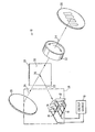
- the test target 10 comprises a heated "hot" target 12 comprised of a plurality of bar elements 14 to provide the test signals.
- a heated "hot" target 12 comprised of a plurality of bar elements 14 to provide the test signals.
- bar elements 14 are provided in the exemplary embodiment, although any convenient number may be used.
- Each of the bar elements 14 is made of a suitable material that can be electrically heated to a high temperature and which has a high emissivity constant.
- An example of such a material is oxidized nickel-chromium alloy. Typical temperatures are in the range of 30 degrees centigrade to 50 degrees centigrade.
- the bar elements 14 are physically supported and electrically connected by means such as wire grids 16, 18 and are in turn supported on a target enclosure (not shown in the drawings) and connected to a controlled source 19 of electrical energy.
- a temperature control maintains the bar elements 14 at a desired temperature above ambient. Only the bar elements 14 need to be heated.
- the bar elements 14 have very small masses, and the power consumption is low.
- the wire grids 16, 18 are positioned behind the elements 14 as will be discussed below.
- a uniform plate or target field 20 which serves as a background and is comprised of a generally planar body and is also made of a material having a high emissivity coefficient such as oxidized nickel-chromium alloy.
- the target field 20 is physically supported within an enclosure (not shown) and is in direct contact with the ambience, thus it is maintained at the ambient temperature.
- the target bar elements 14 and the field 20 are kept at different temperatures.
- the hot target 12 and target field 20 are physically displaced one from the other and are located along orthogonally disposed axes 22, 24 respectively.
- the axes 22, 24 intersect at a point 26.
- An infrared beamsplitter 28 having a partially reflecting surface 30 is disposed at the point 26 and is disposed at an angle of about 45 degrees with respect to the axes 22, 24.
- the partially reflecting surface 30 is typically provided by depositing a thin film of metal (e.g. aluminum) on the surface 30, this being a material suited for reflecting infrared energy.
- the splitting ratio of the beamsplitter 28 determines the proportional constant for the temperature difference between the bar elements 14 and the field 20.
- a typical beamsplitter 28 splitting ratio is 50/50.
- a lens assembly 32 serves as a collimator and is positioned with its optical axis 34 aligned and intersecting the point 26.
- the hot target 12 and the target field 20 are typically located equal distances from the lens assembly 32.
- the lens assembly 32 forms a composite image 36 comprised of an image of the hot target 12 and the target field 20 at an image plane.
- the bar elements 14 and the target field 20 are optically combined to form a four-bar target.
- An infrared equipment to be tested (not shown in the figure) is positioned at the image plane, or at a position to focus the image 36 on its detector elements if the equipment is provided with a lens of its own.
- Equipment to be tested such as a forward looking infrared system, for example, sees this test target 10 as a regular four-bar target with a temperature difference between the field 20 and the bar elements 14 proportional to the true temperature difference.
- the proportional constant is determined by the splitting ratio of the beamsplitter 28.
- the hot target 12, the target field 20, the beamsplitter 28, and the lens assembly 32 are typically disposed within a suitable enclosure (not shown in the figure).
- the test target 10 has dimensions of 1 inch, 1 inch, by 2 inches. It should also be observed that the hot target 12 and the target field 20 may be positioned close to the beamsplitter 28 if the beamsplitter 28 provides a thermal and radiation barrier between the hot target 12 and the target field 20 so as to minimize the thermal gradient therebetween. Alternatively, a suitable thermal shield 38, shown by dashed lines may be positioned between the hot target 12 and the target field 20 to decrease the thermal gradient between the hot target 12 and the field 20.
- the test target 10 of the present invention provides a physical separation of the hot target 12 and the field 20.
- the target field 20 and the target bar elements 14 are physically separated and are kept at different temperatures. Because the target bar elements 14 are separated far apart from the target field 20, the bar elements 14 can be heated to a significantly higher temperature. This creates a higher contrast.
- the hot target 12 and the field 20 may also be made of suitable materials that provide surfaces that substantially approximate a blackbody. Since blackbodies substantially emit or absorb all radiation, the blackbody characteristics of the hot target 12 and the field 20 significantly reduces or eliminates the Narcissus effect and effects due to complicated environmental changes. Positioning of the wire grids 16, 18, behind the heated bar elements 14 shields them from view of a detector under test. Further, because the bar elements 14 are the only elements to be heated and have only small masses, the target 10 has low power consumption.
- the target of the present invention overcomes the difficulty of maintaining an extremely high temperature gradient in the target.
- the target of the present invention provides a greater contrast range than that provided by conventional miniature targets.
- Another feature of the invention is the provision of a miniature infrared test target that is made with surfaces approximating a blackbody, thereby providing immunity from the Narcissus problem and the effects of complicated environmental changes.
Landscapes
- Physics & Mathematics (AREA)
- Electromagnetism (AREA)
- Engineering & Computer Science (AREA)
- General Physics & Mathematics (AREA)
- Radar, Positioning & Navigation (AREA)
- Remote Sensing (AREA)
- Radiation Pyrometers (AREA)
- Photometry And Measurement Of Optical Pulse Characteristics (AREA)
Applications Claiming Priority (2)
| Application Number | Priority Date | Filing Date | Title |
|---|---|---|---|
| US07/475,574 US5041735A (en) | 1990-02-06 | 1990-02-06 | Miniature infrared test target |
| US475574 | 1995-06-07 |
Publications (2)
| Publication Number | Publication Date |
|---|---|
| EP0441534A2 true EP0441534A2 (de) | 1991-08-14 |
| EP0441534A3 EP0441534A3 (en) | 1992-12-16 |
Family
ID=23888179
Family Applications (1)
| Application Number | Title | Priority Date | Filing Date |
|---|---|---|---|
| EP19910300776 Withdrawn EP0441534A3 (en) | 1990-02-06 | 1991-01-31 | Miniature infrared test target |
Country Status (2)
| Country | Link |
|---|---|
| US (1) | US5041735A (de) |
| EP (1) | EP0441534A3 (de) |
Cited By (2)
| Publication number | Priority date | Publication date | Assignee | Title |
|---|---|---|---|---|
| FR2877098A1 (fr) * | 2004-10-22 | 2006-04-28 | Thales Sa | Cible pour systemes de reception a infrarouge |
| FR3147475A1 (fr) * | 2023-03-30 | 2024-10-04 | Safran Electronics & Defense | Mire thermique pour la validation des performances de détecteurs infra-rouge |
Families Citing this family (9)
| Publication number | Priority date | Publication date | Assignee | Title |
|---|---|---|---|---|
| US5523579A (en) * | 1994-04-19 | 1996-06-04 | Northrop Grumman Corporation | Infrared line source projector |
| FR2829344B1 (fr) * | 2001-08-29 | 2004-10-01 | Oreal | Dispositif d'acquisition d'au moins une image d'au moins une partie du visage ou de la chevelure d'une personne |
| DE60121439T2 (de) * | 2001-08-30 | 2007-01-11 | Instrumentarium Corp. | Geometrischer Strahlteiler und Sensor mit einem Detektor aus mehreren Elementen |
| US8368760B1 (en) | 2008-10-16 | 2013-02-05 | Raytheon Company | System and method to generate and display target patterns |
| RU2387969C1 (ru) * | 2008-11-26 | 2010-04-27 | Федеральное государственное унитарное предприятие "Летно-исследовательский институт имени М.М. Громова" | Пассивная инфракрасная мира с системой автоматического регулирования |
| RU2507494C2 (ru) * | 2012-04-18 | 2014-02-20 | Открытое акционерное общество Центральный научно-исследовательский институт "ЦИКЛОН" | Мира для настройки и определения параметров оптико-электронных систем с матричными фотоприемными устройствами и способ ее использования |
| US10907938B2 (en) | 2012-08-17 | 2021-02-02 | Raytheon Company | Infrared camouflage textile |
| CN103308185B (zh) * | 2013-05-31 | 2015-04-01 | 西安应用光学研究所 | 用于四杆靶标扫描的红外辐射计 |
| US10679475B1 (en) | 2019-07-15 | 2020-06-09 | William C. Parlin | System, device, and method for triggering motion detector |
Family Cites Families (11)
| Publication number | Priority date | Publication date | Assignee | Title |
|---|---|---|---|---|
| US3227879A (en) * | 1963-10-21 | 1966-01-04 | Gen Precision Inc | Infrared simulator |
| GB1605241A (en) * | 1968-07-04 | 1985-10-23 | Emi Ltd | Vehicle guidance systems |
| US4173777A (en) * | 1977-06-01 | 1979-11-06 | Cincinnati Electronics Corporation | Jet aircraft and/or missile plume simulator |
| US4299451A (en) * | 1980-04-15 | 1981-11-10 | The United States Of America As Represented By The Secretary Of The Air Force | Minimum resolvable contrast measurement device |
| NO149679C (no) * | 1982-02-22 | 1984-05-30 | Nordal Per Erik | Anordning ved infraroed straalingskilde |
| US4446363A (en) * | 1982-03-01 | 1984-05-01 | The United States Of America As Represented By The Secretary Of The Navy | Target for optically activated seekers and trackers |
| US4598206A (en) * | 1983-07-06 | 1986-07-01 | The Gillette Company | Infrared radiation reference |
| US4647783A (en) * | 1985-05-03 | 1987-03-03 | The United States Of America As Represented By The Secretary Of The Army | Measurement of temporal response of electro-optical systems |
| GB8521931D0 (en) * | 1985-09-04 | 1985-10-09 | British Aerospace | Thermal image producing device |
| US4859080A (en) * | 1988-07-22 | 1989-08-22 | Ssg, Inc. | Dynamic thermal display simulator |
| US4883971A (en) * | 1988-12-19 | 1989-11-28 | The Boeing Company | Method and apparatus for determining infrared signature of objects |
-
1990
- 1990-02-06 US US07/475,574 patent/US5041735A/en not_active Expired - Lifetime
-
1991
- 1991-01-31 EP EP19910300776 patent/EP0441534A3/en not_active Withdrawn
Cited By (2)
| Publication number | Priority date | Publication date | Assignee | Title |
|---|---|---|---|---|
| FR2877098A1 (fr) * | 2004-10-22 | 2006-04-28 | Thales Sa | Cible pour systemes de reception a infrarouge |
| FR3147475A1 (fr) * | 2023-03-30 | 2024-10-04 | Safran Electronics & Defense | Mire thermique pour la validation des performances de détecteurs infra-rouge |
Also Published As
| Publication number | Publication date |
|---|---|
| US5041735A (en) | 1991-08-20 |
| EP0441534A3 (en) | 1992-12-16 |
Similar Documents
| Publication | Publication Date | Title |
|---|---|---|
| US5041735A (en) | Miniature infrared test target | |
| US8164037B2 (en) | Co-boresighted dual-mode SAL/IR seeker including a SAL spreader | |
| US4422758A (en) | Boresighting of airborne laser designation systems | |
| US3989947A (en) | Telescope cluster | |
| US7777207B2 (en) | Methods and apparatus for presenting images | |
| US4811061A (en) | Polychromatic mutual alignment device for an aiming apparatus | |
| KR20020065481A (ko) | 멀티컬러 주시 센서 시스템 | |
| GB2203537A (en) | Measuring radiation from articles | |
| US3745347A (en) | Telescope including an imaging system for radiation in the visible range | |
| US4788428A (en) | Thermodynamics infrared imaging sensor | |
| US4446363A (en) | Target for optically activated seekers and trackers | |
| US5214292A (en) | Dynamic infrared scene display | |
| EP0348437B1 (de) | Messmarkeneinrichtung | |
| US7247852B2 (en) | Methods and apparatus for sensor systems | |
| RU2406056C2 (ru) | Многоканальное оптико-электронное устройство корабельного зенитного комплекса для обнаружения и сопровождения воздушных и надводных целей (варианты) | |
| US5264913A (en) | Reduced combiner helicopter sight system | |
| Laszlo | Temperature and flux vs. geometrical perfection | |
| EP0766124A1 (de) | Haltbares Infrarot-Ziel mit kurzer Antwortzeit | |
| Bender et al. | Design of large pupil relief broadband collimator for use in a MMW/IR HWIL facility | |
| Holt et al. | Scene simulation for passive IR systems | |
| Meier | Novel concept of scene generation and comprehensive dynamic sensor test | |
| US3878393A (en) | Selective emitter offset radiation source for compensating radiation detectors for selective radiation emitted therefrom | |
| RU2722974C1 (ru) | Оптическая система формирования инфракрасного изображения | |
| CN221571243U (zh) | 一种离轴红点瞄准系统 | |
| US6018163A (en) | Lab devices to simulate infrared scenes with hot point targets against given temperature backgrounds |
Legal Events
| Date | Code | Title | Description |
|---|---|---|---|
| PUAI | Public reference made under article 153(3) epc to a published international application that has entered the european phase |
Free format text: ORIGINAL CODE: 0009012 |
|
| AK | Designated contracting states |
Kind code of ref document: A2 Designated state(s): DE FR GB |
|
| PUAL | Search report despatched |
Free format text: ORIGINAL CODE: 0009013 |
|
| AK | Designated contracting states |
Kind code of ref document: A3 Designated state(s): DE FR GB |
|
| 17P | Request for examination filed |
Effective date: 19930525 |
|
| 17Q | First examination report despatched |
Effective date: 19950405 |
|
| STAA | Information on the status of an ep patent application or granted ep patent |
Free format text: STATUS: THE APPLICATION IS DEEMED TO BE WITHDRAWN |
|
| 18D | Application deemed to be withdrawn |
Effective date: 19950817 |