EP0441215A1 - Method for the determination of the calibration factors of a gamma-thermometer and its application - Google Patents
Method for the determination of the calibration factors of a gamma-thermometer and its application Download PDFInfo
- Publication number
- EP0441215A1 EP0441215A1 EP91101067A EP91101067A EP0441215A1 EP 0441215 A1 EP0441215 A1 EP 0441215A1 EP 91101067 A EP91101067 A EP 91101067A EP 91101067 A EP91101067 A EP 91101067A EP 0441215 A1 EP0441215 A1 EP 0441215A1
- Authority
- EP
- European Patent Office
- Prior art keywords
- calibration factor
- gamma
- gamma thermometer
- time
- thermometer
- Prior art date
- Legal status (The legal status is an assumption and is not a legal conclusion. Google has not performed a legal analysis and makes no representation as to the accuracy of the status listed.)
- Ceased
Links
- 238000000034 method Methods 0.000 title claims abstract description 72
- 238000004458 analytical method Methods 0.000 claims abstract description 27
- 230000008569 process Effects 0.000 claims abstract description 18
- 238000012545 processing Methods 0.000 claims abstract description 4
- 230000001788 irregular Effects 0.000 claims abstract description 3
- 238000010438 heat treatment Methods 0.000 claims description 43
- BASFCYQUMIYNBI-UHFFFAOYSA-N platinum Chemical compound [Pt] BASFCYQUMIYNBI-UHFFFAOYSA-N 0.000 claims description 28
- 238000005259 measurement Methods 0.000 claims description 20
- 239000002826 coolant Substances 0.000 claims description 16
- 229910052697 platinum Inorganic materials 0.000 claims description 14
- 230000004044 response Effects 0.000 claims description 11
- 229910052751 metal Inorganic materials 0.000 claims description 7
- 239000002184 metal Substances 0.000 claims description 7
- 230000009257 reactivity Effects 0.000 claims description 6
- 238000012546 transfer Methods 0.000 claims description 6
- 230000015572 biosynthetic process Effects 0.000 claims description 2
- 238000004422 calculation algorithm Methods 0.000 claims description 2
- 238000004364 calculation method Methods 0.000 claims description 2
- 238000001514 detection method Methods 0.000 claims description 2
- 238000013461 design Methods 0.000 abstract description 3
- 230000004907 flux Effects 0.000 abstract 3
- 230000005284 excitation Effects 0.000 description 17
- 238000005253 cladding Methods 0.000 description 11
- 230000006870 function Effects 0.000 description 10
- 229910000679 solder Inorganic materials 0.000 description 9
- 238000001228 spectrum Methods 0.000 description 7
- XKRFYHLGVUSROY-UHFFFAOYSA-N Argon Chemical compound [Ar] XKRFYHLGVUSROY-UHFFFAOYSA-N 0.000 description 6
- 239000006096 absorbing agent Substances 0.000 description 6
- 238000012544 monitoring process Methods 0.000 description 6
- 230000000694 effects Effects 0.000 description 5
- 238000005070 sampling Methods 0.000 description 5
- XEEYBQQBJWHFJM-UHFFFAOYSA-N Iron Chemical compound [Fe] XEEYBQQBJWHFJM-UHFFFAOYSA-N 0.000 description 4
- 230000008859 change Effects 0.000 description 4
- 239000000463 material Substances 0.000 description 4
- 230000035945 sensitivity Effects 0.000 description 4
- 229910000831 Steel Inorganic materials 0.000 description 3
- 229910052786 argon Inorganic materials 0.000 description 3
- 230000006399 behavior Effects 0.000 description 3
- 238000010586 diagram Methods 0.000 description 3
- 238000005516 engineering process Methods 0.000 description 3
- 238000009413 insulation Methods 0.000 description 3
- 230000007774 longterm Effects 0.000 description 3
- 230000005855 radiation Effects 0.000 description 3
- 239000010959 steel Substances 0.000 description 3
- 239000004020 conductor Substances 0.000 description 2
- 238000001816 cooling Methods 0.000 description 2
- 238000011156 evaluation Methods 0.000 description 2
- 239000007789 gas Substances 0.000 description 2
- 230000003993 interaction Effects 0.000 description 2
- 229910052742 iron Inorganic materials 0.000 description 2
- 238000002955 isolation Methods 0.000 description 2
- 239000000523 sample Substances 0.000 description 2
- 238000005476 soldering Methods 0.000 description 2
- 239000011343 solid material Substances 0.000 description 2
- 230000009466 transformation Effects 0.000 description 2
- XLYOFNOQVPJJNP-UHFFFAOYSA-N water Substances O XLYOFNOQVPJJNP-UHFFFAOYSA-N 0.000 description 2
- 229910018072 Al 2 O 3 Inorganic materials 0.000 description 1
- 108010074506 Transfer Factor Proteins 0.000 description 1
- 230000003321 amplification Effects 0.000 description 1
- 230000000052 comparative effect Effects 0.000 description 1
- 125000004122 cyclic group Chemical group 0.000 description 1
- 238000011161 development Methods 0.000 description 1
- 230000018109 developmental process Effects 0.000 description 1
- 238000002474 experimental method Methods 0.000 description 1
- 230000017525 heat dissipation Effects 0.000 description 1
- 230000001771 impaired effect Effects 0.000 description 1
- 238000009434 installation Methods 0.000 description 1
- 239000011810 insulating material Substances 0.000 description 1
- 238000003199 nucleic acid amplification method Methods 0.000 description 1
- 239000010935 stainless steel Substances 0.000 description 1
- 238000005309 stochastic process Methods 0.000 description 1
- 238000012795 verification Methods 0.000 description 1
Images
Classifications
-
- G—PHYSICS
- G21—NUCLEAR PHYSICS; NUCLEAR ENGINEERING
- G21C—NUCLEAR REACTORS
- G21C17/00—Monitoring; Testing ; Maintaining
- G21C17/10—Structural combination of fuel element, control rod, reactor core, or moderator structure with sensitive instruments, e.g. for measuring radioactivity, strain
- G21C17/112—Measuring temperature
-
- G—PHYSICS
- G01—MEASURING; TESTING
- G01J—MEASUREMENT OF INTENSITY, VELOCITY, SPECTRAL CONTENT, POLARISATION, PHASE OR PULSE CHARACTERISTICS OF INFRARED, VISIBLE OR ULTRAVIOLET LIGHT; COLORIMETRY; RADIATION PYROMETRY
- G01J5/00—Radiation pyrometry, e.g. infrared or optical thermometry
- G01J5/10—Radiation pyrometry, e.g. infrared or optical thermometry using electric radiation detectors
- G01J5/12—Radiation pyrometry, e.g. infrared or optical thermometry using electric radiation detectors using thermoelectric elements, e.g. thermocouples
-
- Y—GENERAL TAGGING OF NEW TECHNOLOGICAL DEVELOPMENTS; GENERAL TAGGING OF CROSS-SECTIONAL TECHNOLOGIES SPANNING OVER SEVERAL SECTIONS OF THE IPC; TECHNICAL SUBJECTS COVERED BY FORMER USPC CROSS-REFERENCE ART COLLECTIONS [XRACs] AND DIGESTS
- Y02—TECHNOLOGIES OR APPLICATIONS FOR MITIGATION OR ADAPTATION AGAINST CLIMATE CHANGE
- Y02E—REDUCTION OF GREENHOUSE GAS [GHG] EMISSIONS, RELATED TO ENERGY GENERATION, TRANSMISSION OR DISTRIBUTION
- Y02E30/00—Energy generation of nuclear origin
- Y02E30/30—Nuclear fission reactors
Definitions
- the invention relates to a method for calibrating a gamma thermometer which is in a measuring position on or in the core of a nuclear reactor.
- a gamma thermometer is understood here as follows, as it is e.g. is described in EP-A1-0 243 579.
- thermocouple This consists of a rod surrounded by a cladding tube. At least one thermocouple is arranged in the rod in at least one cavity. In the area of the thermocouple, a rod part is arranged as a gamma absorber and as a thermal bridge.
- thermometers for the purpose of calibrating gamma thermometers, only the heating element method is used, namely outside and inside the reactor core.
- an artificial heating current noise is generated, so that shortened time constants can be obtained due to a special transformation process and so the relevant measured values (reactor flow) can be obtained much faster during the reactor operation using a "speed-up process". So here the heating current noise is used to determine time constants, whereas the noise of reactivity, coolant temperature, an analog / digital converter and an amplifier are only considered as disturbance variables and are not exploited will.
- thermal and nuclear transfer factors K i and K 2 of a gamma thermometer are determined using the heating current method in order to be able to make statements about its thermal and nuclear sensitivity. For this purpose, calibrations are carried out outside and inside the reactor core.
- the object of the invention is to provide a method for calibrating gamma thermometers with which the difficulties described can be avoided and with which the calibration of one or more gamma thermometers can also be carried out while a nuclear reactor, in particular a light water nuclear reactor, is in operation can be carried out in a precise manner - even without the use of electrical heating by means of a heating element, so that the values of the gamma flow or the proportional measured values measured with the gamma thermometer are a reliable image of the real conditions in the core.
- the claims 2 to 5 relate to the basic process feature and its configurations that fluctuations in the process variables 'reactivity' are recorded.
- the fluctuations of the thermohydraulic process variables, in particular the process variables 'coolant temperature', and the fluctuations due to vapor bubble formation in the primary coolant are closely linked to these fluctuations.
- Claims 6 and 7 relate to a calibration method which can be used both outside the operation of a nuclear reactor and during the operation of a nuclear reactor and which consists in that the time constant T * is approximately determined on the basis of artificially generated temperature fluctuations in the gamma thermometer by applying a fluctuating heating current to a heating element located on or in the heating element.
- the heating current is preferably subjected to random fluctuations.
- Such a fluctuation is also known under the term stochastic fluctuation or "pseudo random”. This heating current fluctuation method is only used for rough control or verification of the K * and T * values determined on the basis of the noise analysis of fluctuating process variables.
- the constancy of the calibration or the calibration factor K * can advantageously also be monitored.
- the Fourier analysis is generally suitable as a noise analysis.
- the method is preferred the autoregressive (AR) signal analysis applied, the configurations of which are described in claims 9 to 12.
- the cable bundle 1 consists of six Ni-Cr-Ni thermocouples 2 in the form of two-wire thermoelectric cables, each with the two signal lines 2.1 and 2.2 insulated from one another and to the outside, and a central heating cable 3 with a heating conductor 3.1.
- the cables 2, 3 are gas and watertight in a cladding tube 4 made of corrosion-resistant steel.
- the cable insulation KI envelops the conductors 2.1, 2.2 and 3.1 and consists, for example, of Al 2 O 3 .
- One of the thermocouples 2 is shown schematically with its "hot" solder joint 2a and with its "cold” solder joint 2b; the axes of the other thermocouples 4 are indicated by dash-dotted lines.
- a hollow cylindrical platinum body 5 is soldered or welded to the outer circumference of the cladding tube 4 above the hot soldering point 2a of the respective thermocouple 2.
- An outer envelope 6 encloses a gas space 7 filled with, for example, 1 bar argon.
- a part of this enveloping body 6 is also soldered or welded to the outer circumference of the enveloping tube 4 or the cable bundle 1 over the cold solder joint 2b.
- the connection points of the enveloping body 6 and the enveloping tube 1, which come into contact with the reactor water, are welded, as shown at points 8 and 9.
- the gamma radiation When operating in the reactor core, the gamma radiation is absorbed in the platinum body 5 (the illustration is not to scale, but only in principle) and heats it up.
- the heat flows mainly in the axial direction via the cable bundle 1 and then radially via the cladding tube 4 and the cladding body 6 to the cooling medium. Due to the axially asymmetrical structure of the gamma thermometer, the heat essentially only flows in the direction of the cold solder joint 2b. It is thereby achieved that the influence of the heat transfer from the detector surface into the cooling medium on the temperature at both solder joints is the same or that this heat transfer has no influence on the differential temperature between (2a) and (2b).
- the signal of the gamma thermometer (detector) is therefore independent of cooling conditions as well as heat and temperature gradients.
- the two solder joints 2a, 2b can be constructed as differential thermocouples in one cable, as shown, or as two absolute thermocouples in two cables.
- the absolute thermocouples in addition to the differential temperatures, the absolute temperatures can also be determined (as a level measurement in the event of loss of coolant).
- the gamma thermometer according to FIG. 2 essentially consists of a rod 10, which is surrounded by a cladding tube 4.
- a differential thermocouple 2 with hot and cold soldering points 2a, 2b is arranged in a channel 11 inside the gamma thermometer in addition to a heating cable 3, which is used for calibration with heating current.
- the rod 10 consists of platinum in the region of the thermocouple 2 and steel for the rest.
- the platinum rod part is surrounded as a platinum gamma absorber thermal bridge 12 within the cladding tube 4 by a tubular heat-insulating chamber 7 '. Both measuring points 2a, 2b of the differential thermocouple 2 can be located in the inner region of the chamber 7 '.
- External gamma radiation mainly causes part 12 to heat up through interactions. Since the atomic number and the density of platinum are significantly greater than the values of iron, the amount of heat introduced into platinum is also very large compared to the amount of heat introduced into iron or steel greater.
- platinum at least in the area of the differential thermocouple 2 the sensitivity of the gamma thermometer is greatly increased. The high sensitivity due to the choice of material makes it possible to change the design of the gamma thermometer or to reduce the longitudinal expansion in order to reduce the effects of power and temperature gradients in the reactor core, without reducing the sensitivity to known gamma thermometers. A heat flow to the surface forms in the heated part 12.
- the heat-insulating chamber 7 ' allows an axial flow to arise in part 12, which only bends outside the chamber 7' towards the cladding tube 4. From the temperature difference between the measuring point 2a and the comparative measuring point 2b of the differential thermocouple 2, the heat flow in the gamma-absorber thermal bridge 12 and from it the radiated gamma intensity with a small error range can be determined.
- the heat-insulating material in the chamber 7 ' is either, as explained in FIG. 1, argon or a solid material with low thermal conductivity.
- a platinum-gamma absorber thermal bridge 13 and a heat-insulating chamber 7 ′′ are arranged axially one behind the other, partially overlapping.
- the platinum-gamma absorber thermal bridge 13 touches the cladding tube 4 and thus the tube only at one point Outer skin of the gamma thermometer.
- the chamber 7 "can, like the chamber 7 'according to FIG. 2, contain argon or a solid material with low thermal conductivity.
- thermocouples hot and cold measuring point
- the thermocouples measure temperatures that correspond to the "flowing amounts of heat", which are the sum of all amounts of heat and corresponding to the paths.
- the heating current is selected as a pseudo-random telegraph signal.
- the temperature of the filament then also has a pseudo-random course - neglecting the time constant of the filament, see FIG. 4.
- the dimension of x is 1 / sec.
- the always existing excitation by fluctuations in the coolant temperature can also be used. If the coolant temperature fluctuations are almost uncorrelated in time compared to the sensor bandwidth, the requirement for a white excitation is met sufficiently well. What has been said above applies to the selection of the sampling time and the recording duration.
- the fluctuations in the sensor output signal can then also be analyzed again with AR analysis and the sensor time constant can be estimated.
- the prerequisite for an approximate white excitation due to coolant temperature fluctuations in one of the gamma thermometers is fulfilled.
- the excitation of the gamma thermometer by fluctuation of the gamma flow can also be evaluated for the AR analysis.
- This excitation must meet the requirement of a power density spectrum that is approximately white within the sensor bandwidth, and its power (amplitude) must be sufficient to lead to evaluable fluctuations in the sensor output signal. If the hot measuring point provides sufficient evidence of gamma flow fluctuations - possibly during part-load operation - a good direct calibration results from the determination of the associated time constant.
- the small amplitude of the fluctuations can be compensated for by measuring for a very long time. This is easier possible with the method proposed here because the function of the sensors is not impaired at all by the calibration measurement (without heating current).
- the performance and its influence on the calibration method can be increased by producing measuring elements and parts of the thermal bridge from platinum, because this increases the interactions with the gamma radiation.
- influences of the vapor bubble content can also have an effect on the cooling, in particular on the cold measuring point, and can therefore be measured by an analysis of the time constants.
- thermocouples with corresponding fluctuation analyzes
- the effects can also be separated and can thus be taken into account more easily in the end.
- a gamma thermometer as was explained with reference to FIGS. 1 to 3, or another suitable gamma thermometer is used and generally designated GT.
- the associated gamma thermometer measuring point which is important in the present case, is designated GT1.
- the voltage signal of the gamma thermometer measuring point GT1 is faded out of the signal path relevant for the control system via the isolation and compensation amplifier (a).
- (a) has three functions: galvanic isolation of the control technology (possibly safety-relevant) from the calibration device, compensation of the DC component of the measurement signal by adding a constant, adjustable compensation voltage and amplification of the remaining AC component for optimal control of the subsequent devices.
- the remaining alternating component is due to gamma flow and / or coolant fluctuations.
- the low-pass filter (b) serves to limit the band of the signal in order to avoid errors due to convolutions in the frequency domain during the subsequent digitization.
- the cut-off frequency of the low-pass filter should be selected to be less than half the sampling frequency.
- the measurement signal acquisition and analysis device (c) first digitizes the analog signal u (t) over a certain period of time and stores the data in a storage medium, e.g. Main computer memory, hard disk or diskette d. The data can then be analyzed and the calibration factor determined for the measuring point. Keyboard, monitor and printer e are provided for display and operation. If the calibration is to be monitored, a message is issued when the calibration factor changes, e.g. via a lamp f in the control room, or by hiding the measurement signal from the reactor monitoring system or by automatically adapting the gain factor of the gamma thermometer useful signal in accordance with the new calibration factor.
- a storage medium e.g. Main computer memory, hard disk or diskette d.
- Keyboard, monitor and printer e are provided for display and operation. If the calibration is to be monitored, a message is issued when the calibration factor changes, e.g. via a lamp f in the control room, or by hiding the measurement signal from the reactor monitoring system or by automatically adapting the gain
- the signal processing in the measurement signal detection and analysis device c takes place according to the diagram according to FIG. 6 in the following steps:
- the analog signal u (t) is first digitized by an analog-digital converter cl at cyclic time intervals of T A.
- the sampling time T A is about 1/40 to 1/10 of the smallest time constant of the measuring point.
- the data are read from the memory and an AR analysis is carried out (c3).
- the data x (k) are modeled by an auto-regressive model of order N:
- the time constants can be determined from the frequency response.
- the magnitude-frequency response of the measuring point - apart from a multiplicative constant - is determined from the AR parameters (c6):
- the kinks and thus the time constants can then be determined from the absolute frequency response in (c7).
- the calibration factor of the gamma thermometer or the measuring channel is then determined in (c10) using the relationship already given above.
- This calibration factor can now be used for a corresponding setting of the measuring amplifier for the measuring channel under consideration be det. If the calibration device is to monitor the constancy of the calibration factor, a comparison of the currently determined calibration factor with one or more previously determined calibration factors is carried out in (c11). If there is an impermissibly large difference between these values, a message is generated which is displayed at a suitable point, for example in the control room.
Abstract
Description
Die Erfindung bezieht sich auf ein Verfahren zum Kalibrieren eines Gammathermometers, das sich in einer Meßposition am oder im Kern eines Kernreaktors befindet.The invention relates to a method for calibrating a gamma thermometer which is in a measuring position on or in the core of a nuclear reactor.
Solche Gammathermometer bestehen im allgemeinen aus einer länglichen Meßsonde mit Metallmasse einschließlich Wärmebrücke, Wärmeisolierung, Wärmesenke und aus Einfach- oder Differenzthermoelementen, wobei aufgrund eines der Reaktorleistung proportionalen Gammaflusses eine Wärmemenge pro Zeiteinheit in die Meßsonde eingebracht und ein Wärmefluß von der Metallmasse über die Wärmebrücke zur Wärmesenke hervorgerufen wird und wobei die von den Thermoelementen erfaßten Größen für Temperatur bzw. Temperaturgefälle ein Maß für die eingebrachte Wärmemenge pro Zeiteinheit sind. Es besteht ein Zusammenhang zwischen der pro Zeiteinheit eingebrachten Wärmemenge Q, der mit dem Gammathermometer gemessenen Signalamplitude A U der Meßspannung und T*, der Zeitkonstanten des Responses auf Änderungen von Q, wobei für eine einfache Geometrie eines Gammathermometers mit einer Zeitkonstanten T* gilt:
- C,p = Wärmekapazität bzw. Dichte von Metallmasse einschließlich Wärmebrücke (bekannt),
- F = dimensionsloser Umrechnungsfaktor (bekannt),
- K* = Kalibrierfaktor, wobei bei realen Gammathermometern auch kompliziertere Zusammenhänge zwischen A U und Q mit mehreren Zeitkonstanten T* feststellbar sind.
- C, p = heat capacity or density of metal mass including thermal bridge (known),
- F = dimensionless conversion factor (known),
- K * = calibration factor, with real gamma thermometers also more complicated relationships between AU and Q with several time constants T * can be determined.
Unter Gammathermometer wird hier wie im folgenden ein solches verstanden, wie es z.B. in der EP-A1-0 243 579 beschrieben ist.A gamma thermometer is understood here as follows, as it is e.g. is described in EP-A1-0 243 579.
Dieses besteht aus einem von einem Hüllrohr umgebenen Stab. Im Stab ist in mindestens einem Hohlraum mindestens ein Thermoelement angeordnet. Im Bereich des Thermoelements ist ein Stabteil als Gamma-Absorber und als Wärmebrücke angeordnet.This consists of a rod surrounded by a cladding tube. At least one thermocouple is arranged in the rod in at least one cavity. In the area of the thermocouple, a rod part is arranged as a gamma absorber and as a thermal bridge.
Ein anderes bekanntes Gammathermometer ist in der DE-A1-32 02 560 zusammen mit einem Kalibrierverfahren beschrieben.Another known gamma thermometer is described in DE-A1-32 02 560 together with a calibration method.
Bei einem solchen Gammathermometer, wie auch bei anderen Typen, ist versucht worden, mit Hilfe von elektrischen Strömen durch ein Heizelement, welches an oder im Gammathermometer befestigt ist, eine Kalibrierung des Gammathermometers nicht nur bei Reaktorstillstand, sondern sogar beim Reaktorbetrieb zu ermöglichen.With such a gamma thermometer, as with other types, attempts have been made to enable the gamma thermometer to be calibrated not only when the reactor is at a standstill but also when the reactor is in operation, using electrical currents through a heating element which is attached to or in the gamma thermometer.
Zum Stand der Technik der Kalibrierung von Gammathermometern im einzelnen sei auf den Tagungsband "Proceedings of a Specialist's Meeting on In Core Instrumentation and Reactor Assessment" (Tagung in Cadarache, FR, vom 07. bis 10.06.1988), herausgegeben von der Agence pour l'Energie Nucleaire, verwiesen, insbesondere die Arbeiten
- - "Technology and Use of Gamma Thermometers" von F. Loisy, M. Huver und M. Janvier, S. 271 - 277 (A);
- - "Speeded up Gamma Thermometer Signals for Reactor Protection Systems" von B. Sarnes, L. Magnusson, W. Puhl, K. Siegel und U. Wolff, S. 205 - 212 (B);
- - "Long-term Behavior of Gamma Thermometers in a BWR" von W.O. Oosterkamp und W.H.M. Nissen, S. 278 - 284 (C).
- - "Technology and Use of Gamma Thermometers" by F. Loisy, M. Huver and M. Janvier, pp. 271 - 277 (A);
- - "Speeded up gamma thermometer signals for reactor protection systems" by B. Sarnes, L. Magnusson, W. Puhl, K. Siegel and U. Wolff, pp. 205-212 (B);
- - "Long-term Behavior of Gamma Thermometers in a BWR" by WO Oosterkamp and WHM Nissen, pp. 278 - 284 (C).
Ferner wird verwiesen auf den Tagungsband "Nuclear Power Plant Control and Instrumentation 1982" (Tagung in München vom 11. bis 15.10.1982), herausgegeben von der IAEA, Wien 1983, und zwar die Arbeit "Le Thermometre Gamma" von M. Barbet, G. Beraud und P. Guillery, S. 547 - 561 (D).Reference is also made to the conference volume "Nuclear Power Plant Control and Instrumentation 1982" (conference in Munich from October 11 to 15, 1982), published by the IAEA, Vienna 1983, namely the work "Le Thermometer Gamma" by M. Barbet, G. Beraud and P. Guillery, pp. 547-561 (D).
Bei (A) wird zum Zwecke der Kalibrierung von Gammathermometern nur mit der Heizelement-Methode gearbeitet, und zwar außerhalb und innerhalb des Reaktorkerns.In (A), for the purpose of calibrating gamma thermometers, only the heating element method is used, namely outside and inside the reactor core.
Bei (B) wird ein künstliches Heizstromrauschen erzeugt, damit aufgrund eines besonderen Transformations-Verfahrens verkürzte Zeitkonstanten gewonnen und so während des Reaktorbetriebs mit den Gammathermometern die relevanten Meßwerte (Reaktorfluß) wesentlich schneller im Rahmen eines "Speed up-Verfahrens" gewonnen werden können. Hier wird also mit dem Heizstromrauschen zur Ermittlung von Zeitkonstanten gearbeitet, wogegen das Rauschen von Reaktivität, Kühlmitteltemperatur, eines Analog/Digital-Konverters und eines Verstärkers lediglich als Störgrößen betrachtet und nicht ausgenutzt werden.At (B) an artificial heating current noise is generated, so that shortened time constants can be obtained due to a special transformation process and so the relevant measured values (reactor flow) can be obtained much faster during the reactor operation using a "speed-up process". So here the heating current noise is used to determine time constants, whereas the noise of reactivity, coolant temperature, an analog / digital converter and an amplifier are only considered as disturbance variables and are not exploited will.
In (C) findet sich - ebenso wie in (A) und (B) - die Erkenntnis des Auftretens einer Langzeit-Drift der Zeitkonstanten von Gammathermometern. In (C) wird deshalb von der Notwendigkeit der Kalibrierung in regelmäßigen Intervallen gesprochen. In dieser Arbeit werden indessen nur die Probleme angesprochen; eine während des normalen Reaktorbetriebs ausführbare Kalibriermethode wird nicht angegeben. Eine Berechnung der dreidimensionalen Flußverteilung im Reaktorkem sei, so wird dort festgestellt, zu ungenau. Es würden experimentelle Ergebnisse zu deren Überprüfung benötigt, die Experimente seien verhältnismäßig aufwendig.In (C) - just like in (A) and (B) - the knowledge of the occurrence of a long-term drift of the time constants of gamma thermometers can be found. Therefore (C) speaks of the need for calibration at regular intervals. However, only the problems are addressed in this work; a calibration method that can be carried out during normal reactor operation is not specified. A calculation of the three-dimensional flow distribution in the reactor core is, it is found there, too imprecise. Experimental results would be needed to check them, and the experiments would be relatively expensive.
Bei (D) werden thermische und nukleare Transferfaktoren Ki und K2 eines Gammathermometers mittels der Heizstrommethode ermittelt, um Aussagen über seine thermische und nukleare Empfindlichkeit machen zu können. Hierzu werden Kalibrierungen außerhalb und innerhalb des Reaktorkerns durchgeführt.At (D), thermal and nuclear transfer factors K i and K 2 of a gamma thermometer are determined using the heating current method in order to be able to make statements about its thermal and nuclear sensitivity. For this purpose, calibrations are carried out outside and inside the reactor core.
Wenn man die Zusammenhänge von Heizung und Signal-Amplitude und die damit verbundenen Konsequenzen näher analysiert, gelangt man zu folgenden Erkenntnissen: Die Kalibrierung ist nicht immer vollständig möglich; es ergeben sich eventuell Ungenauigkeiten. Wenn eine Kalibrierung nur auf einer Heizelement-Anregung basiert, so hat das zur Folge, daß bei Ausfall des Heizelements im Grunde das Gammathermometer als Ganzes unbrauchbar wird. Daraus ergeben sich entsprechende Folgekosten, die durch den Ersatz des Gammathermometers im Reaktor bedingt sind.If you analyze the relationships between heating and signal amplitude and the associated consequences in more detail, you will come to the following findings: Calibration is not always completely possible; there may be inaccuracies. If a calibration is based only on a heating element excitation, this means that if the heating element fails, the gamma thermometer as a whole becomes unusable. This results in corresponding follow-up costs, which are due to the replacement of the gamma thermometer in the reactor.
Die Informationen über die Zuverlässigkeit der Kalibrierung mittels Heizstromanregung sind stark begrenzt. Eine Überwachung der Konstanz der Kalibrierung bei Reaktorbetrieb ist nur mit hohem Aufwand und deshalb nur eingeschränkt möglich.The information about the reliability of the calibration using heating current excitation is very limited. Monitoring the constancy of the calibration during reactor operation is only possible with great effort and therefore only to a limited extent.
Ausgehend von diesen Erkenntnissen liegt der Erfindung die Aufgabe zugrunde, ein Verfahren zum Kalibrieren von Gammathermometern anzugeben, mit welchem sich die geschilderten Schwierigkeiten vermeiden lassen und mit welchem auch während des Betriebs eines Kernreaktors, insbesondere eines Leichtwasser-Kernreaktors, sich die Kalibrierung eines oder mehrerer Gammathermometer auf genaue Weise - auch ohne Anwendung einer elektrischen Aufheizung mittels Heizelements - durchführen läßt, so daß die mit dem Gammathermometer gemessenen Werte des Gammaflusses oder der proportionalen Meßwerte ein zuverlässiges Abbild der realen Verhältnisse im Kern sind.Based on these findings, the object of the invention is to provide a method for calibrating gamma thermometers with which the difficulties described can be avoided and with which the calibration of one or more gamma thermometers can also be carried out while a nuclear reactor, in particular a light water nuclear reactor, is in operation can be carried out in a precise manner - even without the use of electrical heating by means of a heating element, so that the values of the gamma flow or the proportional measured values measured with the gamma thermometer are a reliable image of the real conditions in the core.
Zur Lösung der gestellten Aufgabe ist die Erfindung dadurch gekennzeichnet,
- - daß mit auch während des Reaktorbetriebs stets fluktuierenden Prozeßvariablen, wobei das Fluktuieren als ein dem Signalmittelwert der Prozeßvariablen überlagertes Signalrauschen definiert wird, im Gammathermometer ein dem Gammafluß proportionaler und ebenfalls fluktuierender Wärmestrom Ô erzeugt wird,
- - daß mit dem fluktuierenden Wärmestrom Ô im Gammathermometer mit Hilfe von Thermoelementen eine ebenfalls fluktuierende Meßspannung A U(t) erzeugt wird, welche eine Funktion des Produktes aus fluktuierendem Wärmestrom Ô und einem Kalibrierfaktor K* des Gammathermometers ist, wobei der Kalibrierfaktor K* seinerseits je nach Bauart des Gammathermometers mit einer oder mehreren Zeitkonstanten T* des Gammathermometers zusammenhängt, so daß eine Bestimmung der Zeitkonstanten T* der Bestimmung des Kalibrierfaktors K* äquivalent ist,
- - und daß zur Ermittlung des Kalibrierfaktors K* die regellosen und von der Amplitude her unbekannten Fluktuationen der Prozeßvariablen ausgenutzt werden, um in einer Verarbeitungsstufe den Kalibrierfaktor K* durch Bestimmung der Zeitkonstanten T* des Gammathermometers zu ermitteln, wobei letztere durch Methoden der Rauschanalyse, angewendet auf die Meßspannung A U(t), erhalten werden.
- that with fluctuating process variables even during reactor operation, the fluctuation being defined as a signal noise superimposed on the mean signal value of the process variables, a gamma flow proportional and also fluctuating heat flow Ô is generated in the gamma thermometer,
- - That with the fluctuating heat flow Ô in the gamma thermometer with the help of thermocouples, also a fluctuating measurement voltage AU (t) is generated, which is a function of the product of the fluctuating heat flow Ô and a calibration factor K * of the gamma thermometer, the calibration factor K * in turn depending on Design of the gamma thermometer is related to one or more time constants T * of the gamma thermometer, so that a determination of the time constant T * is equivalent to the determination of the calibration factor K * ,
- - And that the irregular fluctuations of the process variables, which are unknown in terms of amplitude, are used to determine the calibration factor K * in order to determine the calibration factor K * in one processing stage by determining the time constant T * of the gamma thermometer, the latter being applied by methods of noise analysis to the measuring voltage AU (t).
Vorteilhafte Weiterbildungen dieses Verfahrens sind in den Patentansprüchen 2 bis 15 angegeben. Dabei beziehen sich die Ansprüche 2 bis 5 auf das grundsätzliche Verfahrensmerkmal und seine Ausgestaltungen, daß Fluktuationen der Prozeßvariablen 'Reaktivität' erfaßt werden. Eng mit diesen Fluktuationen verknüpft sind die Fluktuationen der thermohydraulischen Prozeßvariablen, insbesondere der Prozeßvariablen 'Kühlmitteltemperatur', und die Fluktuationen aufgrund von Dampfblasenbildung im Primärkühlmittel.Advantageous developments of this method are given in
Die Ansprüche 6 und 7 beziehen sich auf eine Kalibriermethode, die sowohl außerhalb des Betriebs eines Kernreaktors als auch während des Betriebs eines Kernreaktors angewendet werden kann, und die darin besteht, daß die Zeitkonstante T* näherungsweise ermittelt wird auf der Grundlage künstlich erzeugter Temperaturfluktuationen im Gammathermometer, indem ein an oder in diesem befindliches Heizelement mit fluktuierendem Heizstrom beaufschlagt wird. Vorzugsweise wird der Heizstrom regellosen Fluktuationen unterworfen. Eine solche Fluktuation ist auch unter dem Begriff stochastische Fluktuation oder "Pseudo Random" bekannt. Diese Heizstrom-Fluktuationsmethode dient nur zur groben Kontrolle oder Verifikation der aufgrund der Rauschanalyse fluktuierender Prozeßvariabler ermittelten K*- und T*-Werte.
Gemäß Anspruch 8 kann vorteilhafterweise auch die Konstanz der Kalibrierung bzw. des Kalibrierfaktors K* überwacht werden.According to
Als Rauschanalyse eignet sich grundsätzlich die Fourier-Analyse. Bevorzugt wird indessen die Methode der autoregressiven (AR-) Signalanalyse angewendet, deren Ausgestaltungen in den Patentansprüchen 9 bis 12 beschrieben sind.The Fourier analysis is generally suitable as a noise analysis. However, the method is preferred the autoregressive (AR) signal analysis applied, the configurations of which are described in claims 9 to 12.
Eine weitere Anspruchsgruppe (Ansprüche 13 und 14) befaßt sich damit, wie die ermittelten Kalibrierfaktoren zur Kalibrierung der Meßsignale verwertet werden können.Another group of claims (
Gemäß Anspruch 15 wird zum selektiven Erfassen des Reaktivitätsrauschens und damit zur Erleichterung und Verbesserung der Analyse der Zeitkonstanten T* und der Bestimmung des Kalibrierfaktors K* Platin (Z = 78) als Metallmasse und gegebenenfalls Wärmebrücke im Gammathermometer verwendet.According to claim 15 is used to selectively detect the reactivity noise and thus to facilitate and improve the analysis of the time constant T * and the determination of the calibration factor K * platinum (Z = 78) as a metal mass and optionally thermal bridge in the gamma thermometer.
Gegenstand der Erfindung ist auch die Verwendung des vorbeschriebenen Verfahrens, soweit dieses die während des Reaktorbetriebs auftretenden Fluktuationen zur Ermittlung der Zeitkonstanten oder des Kalibrierfaktors ausnutzt, wie dies in einem der Ansprüche 1 bis 5 oder 9 bis 15 beschrieben ist, zur kontinuierlichen Ermittlung der Zeitkonstanten während des Reaktorbetriebs für ein Speed up-Verfahren, bei dem durch Anwendung eines Transfer-Funktions-Algorithmus auf das Zeitverhalten des jeweiligen Gamma- thermometers aufgrund der ermittelten Zeitkonstanten T, des Ausgangssignals xa (t) sowie der ersten Ableitung xa(t) und eventuell zweiten Ableitung des Ausgangssignals des Gammathermometers ein "Speeded up-Signal" xs(t) gewonnen wird, welches z.B. durch die folgenden Gleichungen definiert ist:
- a) bei einem einfachen Gammathermometer durch xs(t) = xa(t) + T* . xa(t) und
- b) bei einem speziellen Gammathermometer mit erstem und zweitem Thermoelement bzw. Differenzthermoelement und den beiden Zeitkonstanten T; und T; und mit der zweiten Ableitung Xa(t) des Ausgangssignals xa(t) durch

- a) with a simple gamma thermometer by x s (t) = x a (t) + T *. x a (t) and
- b) in a special gamma thermometer with first and second thermocouple or differential thermocouple and the two time constants T; and T; and with the second derivative X a (t) of the output signal x a (t)
Ein solches Speed up-Verfahren ist in der weiter oben zitierten Literaturstelle (B) beschrieben, wobei jedoch zur kontinuierlichen Ermittlung der Zeitkonstanten lediglich das durch Heizelemente hervorgerufene Heizstromrauschen verwendet wird; das Reaktivitätsrauschen, die Kühlmitteltemperatur-Fluktuationen und so weiter werden lediglich als Störgrößen betrachtet. Gemäß der vorliegenden Erfindung kann das sogenannte Speed up-Verfahren, hinsichtlich dessen näherer Funktion ausdrücklich auf die vorgenannte Literaturstelle (B) verwiesen wird, genauer verwirklicht werden, wenn die erforderlichen Zeitkonstanten der Gammathermometer nicht durch ein Näherungsverfahren wie es nun einmal die Heizstromrausch-Methode darstellt, ermittelt werden, sondern durch die Ausnutzung des Reaktorkenngrößen-Rauschens gemäß der vorliegenden Erfindung während des normalen Reaktorbetriebs.Such a speed-up method is described in reference (B) cited above, but only the heating current noise caused by heating elements is used for the continuous determination of the time constant; the reactivity noise, the coolant temperature fluctuations and so on are only considered as disturbances. According to the present invention, the so-called speed-up method, with regard to the more detailed function of which reference is expressly made to the aforementioned reference (B), can be implemented more precisely if the required time constants of the gamma thermometers are not achieved by an approximation method such as the heating current noise method , but by utilizing the reactor characteristic noise according to the present invention during normal reactor operation.
Im folgenden wird der Gegenstand der Erfindung anhand mehrerer, in der Zeichnung dargestellter Ausführungsbeispiele noch näher erläutert, und zwar anhand dreier Ausführungsbeispiele für ein Gamma- thermometer, anhand eines Diagramms für eine Pseudo-Zufalls-Heizstromanregung und anhand eines Ausführungsbeispiels für eine Kalibriereinrichtung mit einem Analyse-Gerät.The subject matter of the invention is explained in more detail below with the aid of a number of exemplary embodiments shown in the drawing, namely with three exemplary embodiments for a gamma thermometer, with a diagram for pseudo-random heating current excitation and with an exemplary embodiment for a calibration device with an analysis -Device.
In der beiliegenden Zeichnung zeigen im einzelnen in teils schematischer, vereinfachter Darstellung:
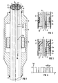
- FIG 1 ein Platin-Gammathermometer im Ausschnitt, wie es zum Einbau in einen Meßkanal eines Kernreaktors dient,
- FIG 2 eine Variante zum Gamma-
Thermometer nach Figur 1 in einem weiter verkleinerten Ausschnitt, - FIG 3 eine weitere Ausführungsform eines Gammathermometers im Ausschnitt,
- FIG 4 ein Diagramm, in welchem Heizstrom-Intervalle i(t) mit einer Intervallbreite A t; und den Maxima A über der Zeitachse t aufgetragen sind, welche zur Pseudo-Zufalls-Heizstromanregung eines zu kalibrierenden Gammathermometers dienen;
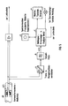
- FIG 5 eine Kalibriereinrichtung für das von einem Gammathermometer abgegebene Meßsignal in Funktionsblock-Darstellung und
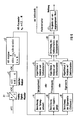
- FIG 6 das Analyse-
Gerät nach Figur 5 vergrößert im Detail, ebenfalls in Funktionsblock-Darstellung.
- 1 shows a cutout of a platinum gamma thermometer as it is used for installation in a measuring channel of a nuclear reactor,
- 2 shows a variant of the gamma thermometer according to FIG. 1 in a further reduced detail,
- 3 shows a further embodiment of a gamma thermometer in a cutout,
- 4 shows a diagram in which heating current intervals i (t) with an interval width A t; and the maxima A are plotted over the time axis t, which are used for pseudo-random heating current excitation of a gamma thermometer to be calibrated;
- 5 shows a calibration device for the measurement signal emitted by a gamma thermometer in a functional block representation and
- 6 shows the analysis device according to FIG. 5 enlarged in detail, likewise in a functional block representation.
Gemäß Figur 1 besteht das Kabelbündel 1 aus sechs Ni-Cr-Ni-Thermoelementen 2 in Form zweiadriger thermoelektrischer Kabel, jeweils mit den beiden gegeneinander und nach außen isolierten Signalleitungen 2.1 und 2.2, und einem zentralen Heizkabel 3 mit Heizleiter 3.1. Die Kabel 2, 3 sind gas- und wasserdicht in einem Hüllrohr 4 aus korrosionsbeständigem Stahl untergebracht. Die Kabel-Isolierung KI umhüllt die Leiter 2.1, 2.2 und 3.1 und besteht z.B. aus Al2O3. Eines der Thermoelemente 2 ist mit seiner "heißen" Lötstelle 2a und mit seiner "kalten" Lötstelle 2b schematisch dargestellt; die Achsen der übrigen Thermoelemente 4 sind durch strichpunktierte Linien angedeutet. Über der heißen Lötstelle 2a des jeweiligen Thermoelements 2 ist ein hohlzylindrischer Platinkörper 5 auf den Außenumfangs des Hüllrohrs 4 aufgelötet oder an diesen angeschweißt. Ein äußerer Hüllkörper 6 schließt einen Gasraum 7, gefüllt mit z.B. 1 bar Argon, ein. Ein Teil dieses Hüllkörpers 6 ist über der kalten Lötstelle 2b ebenfalls auf den Außenumfang des Hüllrohrs 4 bzw. des Kabelbündels 1 aufgelötet oder an diesen angeschweißt. Die Verbindungsstellen von Hüllkörper 6 und Hüllrohr 1, welche mit dem Reaktorwasser in Berührung kommen, sind geschweißt, wie es an den Stellen 8 und 9 dargestellt ist.According to FIG. 1, the
Bei Betrieb im Reaktorkern wird die Gammastrahlung im Platinkörper 5 (die Darstellung ist nicht maßstabsgerecht, sondern nur prinzipiell) absorbiert und heizt diesen auf. Die Wärme fließt hauptsächlich in axialer Richtung über das Kabelbündel 1 und dann radial über das Hüllrohr 4 und den Hüllkörper 6 an das Kühlmedium ab. Durch den axial unsymmetrischen Aufbau des Gammathermometers fließt die Wärme im wesentlichen nur in Richtung der kalten Lötstelle 2b. Dadurch wird erreicht, daß der Einfluß des Wärmeübergangs von der Detektoroberfläche ins Kühlmedium auf die Temperatur an beiden Lötstellen gleich ist bzw. daß dieser Wärmeübergang auf die Differenztemperatur zwischen (2a) und (2b) keinen Einfluß hat. Das Signal des Gammathermometers (Detektors) ist deshalb unabhängig von Kühlbedingungen sowie Wärme-und Temperaturgradienten.When operating in the reactor core, the gamma radiation is absorbed in the platinum body 5 (the illustration is not to scale, but only in principle) and heats it up. The heat flows mainly in the axial direction via the
Die beiden Lötstellen 2a, 2b (und entsprechende Lötstellen bei den anderen Thermoelementen) können als Differenzthermoelement in einem Kabel, wie dargestellt, oder aber als zwei absolute Thermoelemente in zwei Kabeln aufgebaut sein. Mit den absoluten Thermoelementen lassen sich neben den Differenztemperaturen auch noch die Absoluttemperaturen bestimmen (als Füllstandsmessung bei Kühlmittelverlust).The two
Das Gammathermometer nach Figur 2 besteht im wesentlichen aus einem Stab 10, der von einem Hüllrohr 4 umgeben ist. In einem Kanal 11 im Inneren des Gammathermometers ist neben einem Heizkabel 3, das der Kalibrierung mit Heizstrom dient, ein Differenzthermoelement 2 mit heißer und kalter Lötstelle 2a, 2b angeordnet. Der Stab 10 besteht im Bereich des Thermoelements 2 aus Platin und im übrigen aus Stahl. Der Platinstabteil ist als Platin-Gammaabsorber-Wärmebrücke 12 innerhalb des Hüllrohrs 4 teilweise von einer rohrförmigen wärmeisolierenden Kammer 7' umgeben. Beide Meßstellen 2a, 2b des Differenzthermoelements 2 können sich im inneren Bereich der Kammer 7' befinden. Von außen einfallende Gammastrahlung bewirkt über Wechselwirkungen hauptsächlich eine Erwärmung des Teils 12. Da die Kernladungszahl und die Dichte von Platin deutlich größer sind als die Werte von Eisen, ist auch die in Platin eingebrachte Wärmemenge im Vergleich zu der in Eisen oder Stahl eingebrachten Wärmemenge sehr viel größer. Durch die Verwendung von Platin zumindest im Bereich des Differenzthermoelements 2 wird also die Empfindlichkeit des Gammathermometers stark erhöht. Die hohe Empfindlichkeit aufgrund der Materialwahl gestattet es, zur Reduzierung der Einflüsse von Leistungs- und Temperaturgradienten im Reaktorkern die Konstruktion des Gammathermometers zu ändern bzw. die Längsausdehnung zu reduzieren, ohne daß die Empfindlichkeit gegenüber bekannten Gammathermometern sinkt. Im erwärmten Teil 12 bildet sich ein Wärmefluß zur Oberfläche hin aus. Die wärmeisolierende Kammer 7' läßt im Teil 12 eine axiale Strömung entstehen, die erst außerhalb der Kammer 7' zum Hüllrohr 4 hin abbiegt. Aus der Temperaturdifferenz zwischen der Meßstelle 2a und der Vergleichsmeßstelle 2b des Differenzthermoelements 2 läßt sich der Wärmefluß in der Gamma-Absorber-Wärmebrücke 12 und daraus die eingestrahlte Gammaintensität mit geringer Fehlerbreite bestimmen. Das wärmeisolierende Material in der Kammer 7' ist entweder, wie bei Figur 1 erläutert, Argon oder ein festes Material mit kleiner Wärmeleitfähigkeit.The gamma thermometer according to FIG. 2 essentially consists of a
Im Gammathermometer nach Figur 3 sind eine Platin-Gamma-Absorber-Wärmebrücke 13 und eine wärmeisolierende Kammer 7" axial hintereinander, teilweise überlappend, angeordnet. Die Platin-Gamma- Absorber-Wärmebrücke 13 berührt dabei nur an einer Stelle das Hüllrohr 4 und damit die Außenhaut des Gammathermometers.3, a platinum-gamma absorber
Folglich fließt die durch die Gammaquanten eingebrachte-Wärmemenge in einer Richtung, in Figur 3 nach unten, zum Hüllrohr 4 hin ab. Da die Platin-Gamma-Absorber-Wärmebrücke 13 und das Hüllrohr 4 nur an einer Stelle in Kontakt stehen, wird die Abhängigkeit der Meßwerte von Temperaturgradienten eliminiert. Die Kammer 7" kann wie die Kammer 7' nach Figur 2 Argon oder ein festes Material kleiner Wärmeleitfähigkeit enthalten.Consequently, the amount of heat introduced by the gamma quanta flows in one direction, downwards in FIG. 3, towards the
Im folgenden werden zunächst allgemeine Erläuterungen zum besseren Verständnis des Verfahrens nach der Erfindung gegeben, welches mit Gammathermometern nach Figuren 1 bis 3 ausführbar ist, und sodann werden die Pseudo-Zufalls-Heizstromanregung, eine Einrichtung zur Kalibrierung der von einem Gammathermometer abgeleiteten Meßsignale und die in letzterer enthaltene Einrichtung zur autoregressiven Signalanalyse, die zur Ableitung der Zeitkonstanten und der Kalibrierfaktoren dient, näher erläutert. Der Text ist zur besseren Übersicht in einzelne Kapitel untergliedert. Als Hintergrund-Information werden zunächst die Zusammenhänge zwischen den Signal-Amplituden und den Zeitkonstanten aufgezeigt.In the following, general explanations are given for a better understanding of the method according to the invention, which can be carried out with gamma thermometers according to Figures 1 to 3, and then the pseudo-random heating current excitation, a device for calibrating the measurement signals derived from a gamma thermometer and the in the latter contained device for autoregressive signal analysis, which is used to derive the time constants and the calibration factors, explained in more detail. For a better overview, the text is divided into individual chapters. The background information shows the relationships between the signal amplitudes and the time constants.
Das Funktionsprinzip einer Gammathermometers ist bekanntlich:
- Eine (durch Gammafluß eingebrachte oder durch Heizstrom erzeugte oder anders) in einem Materiestück gesammelte Wärmemenge fließt über eine Wärmebrücke zur Wärmesenke. Dabei werden Wärmeverluste (Wärmemengen, die nicht über die Brücke, sondern anders abfließen) durch geeignete Isolationen möglichst gering gehalten. Aufgrund des Wärmeflusses längst der Brücke entsteht ein Temperaturgefälle, das ein Maß für die eingebrachte Wärmemenge ist.
- A quantity of heat (brought in by gamma flow or generated by heating current or otherwise) in a piece of material flows over a thermal bridge to the heat sink. In this way, heat losses (amounts of heat that do not flow over the bridge, but flow out differently) are kept as low as possible by means of suitable insulation. Due to the heat flow along the bridge, there is a temperature gradient that is a measure of the amount of heat introduced.
Aufgrund dieser Funktionsweise ist eine enge Korrelation der Zeitkonstanten, mit der Sprünge in der Wärmezufuhr meßbar sind, mit den resultierenden Veränderungen der Signal-Amplituden plausibel, z. B.: Ist die Brücke geometrisch lang und schmal, so wird ein großer Temperaturgradient entstehen (= Amplitude des Signals groß), aber es wird auch eine entsprechend lange Zeit dauern, bis sich ein neues Gleichgewicht zwischen Wärmezufuhr und Wärmeabfuhr eingestellt hat (= große Zeitkonstante).Because of this mode of operation, a close correlation of the time constant with which jumps in the heat supply can be measured is plausible with the resulting changes in the signal amplitudes, e.g. E.g .: If the bridge is geometrically long and narrow, there will be a large temperature gradient (= amplitude of the signal large), but it will also take a correspondingly long time until a new balance between heat supply and heat dissipation has been established (= large time constant ).
Genauere Überlegungen für ein spezielles Gamma-Thermometer (J. S. Stutheit, "Fast-Response Gamma Thermometers", Nuclear Instruments and Methods 63 (1968), pp. 300-306) zeigen:
- A U = L2 Q/(2q K) und
- T* = 0.466 CL2 p /(q K) mit:
- U = Signal-Amplitude
- L = Länge der Wärmebrücke
- Ô = pro Zeiteinheit eingebrachte Wärmemenge
- q = Querschnitt der Wärmebrücke (Faktor in Originalliteratur nicht berücksichtigt)
- K = Wärmeleitfähigkeit
- T* = Zeitkonstante
- C = Wärme-Kapazität der Metallmasse
- p = Dichte der Metallmasse
- AU = L 2 Q / (2q K) and
- T * = 0.466 CL 2 p / (q K) with:
- U = signal amplitude
- L = length of the thermal bridge
- Ô = amount of heat introduced per unit of time
- q = cross section of the thermal bridge (factor not taken into account in the original literature)
- K = thermal conductivity
- T * = time constant
- C = heat capacity of the metal mass
- p = density of the metal mass
Es folgt damit auch: A U ist unabhängig von der Geometrie proportional zu T:
Oder anders ausgedrückt:
- Eine Messung von T* ist äquivalent zur Bestimmung des Kalibrierfaktors bzw.
- eine Überwachung der Konstanz von T* entspricht einer Überwachung der Kalibrierung.
- A measurement of T * is equivalent to determining the calibration factor or
- monitoring the constancy of T * corresponds to monitoring the calibration.
Bei den Betrachtungen des Zusammenhangs von Signal-Amplitude und Zeitkonstante im vorigen Kapitel wurden ideale Voraussetzungen und eine stark vereinfachte Geometrie angenommen. Bei einem realen Gammathermometer (siehe Beschreibung des Gammathermometers zu Figur 1 bis 3) liegen sehr viel komplexere Verhältnisse vor:
- - verschiedene Materialien an verschiedenen Stellen (Platin, Stahl, Kabel, Lot)
- - verschlungenere Wege für die an verschiedenen Stellen eingebrachten Wärmemengen.
- - different materials in different places (platinum, steel, cable, solder)
- - more tortuous paths for the amounts of heat introduced at different points.
Infolgedessen messen die Thermoelemente (heiße und kalte Meßstelle) Temperaturen, die den "vorbeifließenden Wärmemengen" entsprechen, die sich als Summe aller Wärmemengen und entsprechend den Wegen ergeben. Man kann sich zu den verschiedenen Wärmemengen und Wärmewegen aber auch Zeitkonstanten zugehörig denken. Man darf allerdings nicht den Fehler machen, die Meßsignalamplituden und die Zeitkonstanten als völlig entkoppelt (insbesondere in ihrem zeitlichen Verlauf) anzunehmen. So kann sich nach einer Änderung der eingebrachten Wärmemenge durch einen eventuellen Wärmestau an einer engen Wegstrecke zur Wärmesenke dies durchaus durch eine Änderung des Signals an der heißen Meßstelle (also up-stream) vorübergehend bemerkbar machen. Unter Beachtung dieser Zusammenhänge kann man aber durchaus im Gammathermometer ablaufenden Teilprozessen auch entsprechende Zeitkonstanten zuordnen. Bei erfindungsgemäß untersuchten Gammathermometern wurde außer den zwei mit der heißen Meßstelle und der kalten Meßstelle in Zusammenhang gebrachten Zeitkonstanten eine dritte Zeitkonstante zur Erklärung der experimentellen Ergebnisse in Erwägung gezogen.As a result, the thermocouples (hot and cold measuring point) measure temperatures that correspond to the "flowing amounts of heat", which are the sum of all amounts of heat and corresponding to the paths. One can think of the different heat quantities and heat paths as belonging to time constants. However, one must not make the mistake of assuming the measurement signal amplitudes and the time constants as completely decoupled (in particular in terms of their timing). After a change in the amount of heat introduced due to a possible heat build-up on a narrow path to the heat sink, this may well be due to a change in the signal at the hot Make the measuring point (i.e. up-stream) temporarily noticeable. Taking these interrelationships into account, one can certainly also assign corresponding time constants to sub-processes running in the gamma thermometer. In the case of gamma thermometers investigated according to the invention, in addition to the two time constants associated with the hot measuring point and the cold measuring point, a third time constant was considered to explain the experimental results.
Fazit: Obwohl die Zusammenhänge zwischen den Signal-Amplituden und den Zeitkonstanten bei komplexen Instrumenten z.Z. nicht genau bekannt sind, gibt es Zusammenhänge ähnlich wie beim einfachen Modell, die zu Kalibrierzwecken herangezogen werden können.Conclusion: Although the relationships between the signal amplitudes and the time constants for complex instruments are currently are not exactly known, there are relationships similar to the simple model that can be used for calibration purposes.
Deshalb ist es sinnvoll, Methoden zur Bestimmung der Zeitkonstanten zu erörtern, wobei von den im folgenden diskutierten Meßmethoden die Methoden 3.2 und 3.3 deshalb besonders interessant sind, weil sie sogar ohne Heizfaden auskommen und deshalb grundsätzlich auch bei Gammathermometern anwendbar sind (d.h. Kalibrierung ermöglichen), wo die Heizmöglichkeit ausgefallen oder gar nicht erst vorgesehen ist.Therefore, it makes sense to discuss methods for determining the time constant, whereby of the measuring methods discussed below, methods 3.2 and 3.3 are particularly interesting because they do not require a filament and can therefore also be used with gamma thermometers (ie enable calibration), where the heating option has failed or is not provided at all.
Alle drei hier vorgeschlagenen Methoden basieren auf dem Prinzip der Noise-Analysis mit Hilfe der autoregressiven Analyse (AR-Analyse). Allen Methoden gemeinsam ist, daß sie sich während des Leistungsbetriebs der Anlage und, ohne die Funktion des Meßkanals zu beeinträchtigen, durchführen lassen. Stellte bisher das Signalrauschen für den Betrieb des Reaktors eine unerwünschte Störung dar, so wird bei der Methode nach der Erfindung gerade das Signalrauschen zu Kalibrierzwecken ausgenutzt.All three methods proposed here are based on the principle of noise analysis with the help of autoregressive analysis (AR analysis). All methods have in common that they can be carried out while the system is operating and without impairing the function of the measuring channel. So far, the signal noise has been an undesirable disturbance for the operation of the reactor, but in the method according to the invention the signal noise is used for calibration purposes.
Der Heizstrom wird als pseudo-zufälliges Telegrafen-Signal gewählt. Die Temperatur des Heizfadens hat dann - unter Vernachlässigung der Zeitkonstante des Heizfadens - ebenfalls einen pseudo-zufälligen Verlauf, vergl. Figur 4.The heating current is selected as a pseudo-random telegraph signal. The temperature of the filament then also has a pseudo-random course - neglecting the time constant of the filament, see FIG. 4.
Die Zufallsvariable A ti ist exponential-verteilt mit der Wahrscheinlichkeitsdichtefunktion p Δt (Δ ti) = e-λ Δ ti wobei der Mittelwert der Δ ti, E{ Δ ti} = 1/λ ist. Die Dimension von x ist 1/sec. Der Mittelwert von i(t) ergibt sich sofort zu E {i (t)} = A/2 ;The random variable A t i is exponentially distributed with the probability density function p Δt (Δ t i ) = e -λ Δ t i , the mean value being Δ t i , E {Δ t i } = 1 / λ. The dimension of x is 1 / sec. The mean of i (t) is immediately given by E {i (t)} = A / 2;
Für die Autokorrelierte von i(t) erhält man (vergl. Papoulis, "Probability, Random Variables, and Stochastic Processes, Second Edition, 1985, S. 212):
- φii (r) = E {i(t) i(t-τ)} = A2/4 + A2/2 e-2λ |τ|
- und damit für das Leistungs-Dichtespektrum von i(t):

- ii φ (r) = E {i (t) i (t-τ)} = A2 / 4 + A 2/2 e -2λ | τ |
- and thus for the power density spectrum of i (t):
Die Übertragungsfunktion des Sensor-Elements von der Heizstrom-Anregung zum Anzeigesignal u(t) wird durch ein System 1. Ordnung beschrieben:
- φii (T) = A2/4 + A2/2 δ0 (T)
- ii φ (T) = A 2/4 + A 2/2 δ 0 (T)
Unter Berücksichtigung der Tatsache, daß gilt:
![]()
![]()
Das Leistungs-Dichte-Spektrum des durch das Heizsignal verursachten Anteils des Anzeigesignals u(t) ergibt sich damit zu:The power-density spectrum of the portion of the display signal u (t) caused by the heating signal thus results in:
Die Gesamtleistung des durch das Heizsignal im Anzeigesignal verursachten Anteils ergibt sich dann als Integral über das Leistungs-Dichte-Spektrum von u(t) zu:

Der Mittelwert von i(t) bewirkt einen konstanten, aber bekannten, Temperaturbeitrag zum Meßsignal des Gamma-Thermometers, und damit einen Anzeige-Offset µu, der aber nachträglich wieder subtrahiert werden kann. Die durch das Heizsignal im Anzeigesignal erzeugte Varianz ist ![]()
- A = 10 Ampere

- A = 10 amps
Damit ist gezeigt, daß man unter realistischen Annahmen auf diese Weise einen auswertbaren Meßeffekt erreicht. Die durch die Heizstromanregung bewirkte Fluktuation des Sensor-Signals kann nun verwendet werden, um mit Hilfe von AR-Analyse die Sensor-Zeitkonstante T* zu bestimmen. Erfahrungen mit der AR-Analyse verschiedener Temperatur-Signale zeigen, daß ein Datensatz von ca. 4000 Werten benötigt wird. Die Abtastzeit TA muß dabei ca. 1/10 bis 1/40 der Sensor-Zeitkonstante betragen. Die Sensor-Zeitkonstante T beträgt hier typisch 15 s. Damit ergibt sich eine gesamte Meßdauer von ca.
- 4000 TA
- = 4000'( 1/10 ... 1/40)* T*
- = 4000'( 1/10 ... 1/40 15 s = 100 .. 25 min.
- 4000 T A
- = 4000 '(1/10 ... 1/40) * T *
- = 4000 '(1/10 ... 1/40 15 s = 100 .. 25 min.
Statt einer künstlichen Anregung durch einen Heizstrom kann auch die immer vorhandene Anregung durch Schwankungen der Kühlmitteltemperatur ausgenutzt werden. Wenn die Kühlmittel-Temperatur-Schwankungen im Vergleich zur Sensor-Bandbreite nahezu zeitlich unkorreliert sind, ist die Voraussetzung einer weißen Anregung hinreichend gut erfüllt. Für die Wahl der Abtastzeit und die Aufzeichnungsdauer gilt das oben Gesagte.Instead of an artificial excitation by a heating current, the always existing excitation by fluctuations in the coolant temperature can also be used. If the coolant temperature fluctuations are almost uncorrelated in time compared to the sensor bandwidth, the requirement for a white excitation is met sufficiently well. What has been said above applies to the selection of the sampling time and the recording duration.
Die Fluktuationen im Sensor-Ausgangssignal können dann ebenfalls wieder mit AR-Analyse analysiert werden und die Sensor-Zeitkonstante geschätzt werden. Die Voraussetzung einer näherungsweisen weißen Anregung durch Kühlmittel-Temperatur-Schwankungen bei einem des Gamma-Thermometer sind erfüllt.The fluctuations in the sensor output signal can then also be analyzed again with AR analysis and the sensor time constant can be estimated. The prerequisite for an approximate white excitation due to coolant temperature fluctuations in one of the gamma thermometers is fulfilled.
Diese Methode funktioniert besonders gut bei der kalten Meßstelle des Gamma-Thermometers, die dem Kühlmittel am stärksten ausgesetzt ist.This method works particularly well with the cold measuring point of the gamma thermometer that is most exposed to the coolant.
Prinzipiell ist auch die Anregung des Gamma-Thermometers durch Fluktuation des Gamma-Flusses für die AR-Analyse auswertbar. Diese Anregung muß die Voraussetzung eines innerhalb der Sensor-Bandbreite näherungsweise weißen Leistungsdichtespektrums erfüllen, und von ihrer Leistung (Amplitude) her ausreichen, um zu auswertbaren Fluktuationen des Sensor-Ausgangssignals zu führen. Wenn die heiße Meßstelle Gammafluß-Fluktuationen - eventuell bei Teillastbetrieb - ausreichend nachweist, ergibt sich eine gute direkte Kalibrierung durch die Bestimmung der damit assoziierten Zeitkonstante.In principle, the excitation of the gamma thermometer by fluctuation of the gamma flow can also be evaluated for the AR analysis. This excitation must meet the requirement of a power density spectrum that is approximately white within the sensor bandwidth, and its power (amplitude) must be sufficient to lead to evaluable fluctuations in the sensor output signal. If the hot measuring point provides sufficient evidence of gamma flow fluctuations - possibly during part-load operation - a good direct calibration results from the determination of the associated time constant.
Die kleine Amplitude der Fluktuationen kann dadurch gut ausgeglichen werden, daß man sehr lange mißt. Dies ist bei der hier vorgeschlagenen Methode deshalb leichter möglich, weil die Funktion der Sensoren durch die Kalibrierungsmessung (ohne Heizstrom) überhaupt nicht beeinträchtigt wird.The small amplitude of the fluctuations can be compensated for by measuring for a very long time. This is easier possible with the method proposed here because the function of the sensors is not impaired at all by the calibration measurement (without heating current).
Wünscht man eine Kalibrierung speziell durch Schwankungen des Gammaflusses, so lassen sich die Leistung und ihr Einfluß auf das Kalibrierverfahren verstärken, indem man Meßkörper und Teile der Wärmebrücke aus Platin fertigt, weil dadurch die Wechselwirkungen mit der Gammastrahlung verstärkt werden.If calibration is specifically desired due to fluctuations in the gamma flow, the performance and its influence on the calibration method can be increased by producing measuring elements and parts of the thermal bridge from platinum, because this increases the interactions with the gamma radiation.
Für die Wahl der Abtastzeit und der Aufzeichnungsdauer gilt dasselbe wie in den vorangegangenen Abschnitten.The same applies to the selection of the sampling time and the recording duration as in the previous sections.
Die Problematik des Einflusses der Positionierung der Lötstellen oder der Veränderung der Eigenschaften im Betrieb sollte mit den drei Methoden der Bestimmung der Zeitkonstanten gut überwacht werden können. Für diese Überwachung und um Effekte (Zeitkonstanten) besser zuordnen zu können (siehe auch unten), sollten einfache Thermoelemente und nicht Differenzthermoelemente benutzt werden, also mindestens je eines für die "heiße" und die "kalte" Meßstelle.The problem of the influence of the positioning of the solder joints or the change in properties in operation should be able to be monitored well with the three methods of determining the time constant. For this monitoring and to be able to better assign effects (time constants) (see also below), simple thermocouples and not differential thermocouples should be used, ie at least one each for the "hot" and the "cold" measuring point.
Insbesondere für eine online-Überwachung ohne Störung des Reaktorbetriebs bieten sich die Analysemethoden des Rauschens nach 3.2 und 3.3 anThe analysis methods for noise according to 3.2 and 3.3 are particularly useful for online monitoring without disturbing reactor operation
Was die Problematik des Gammaspektrums in Abhängigkeit vom Dampfblasengehalt und Abbrand angeht, so können sich Einflüsse des Dampfblasengehalts auch auf die Kühlung, insbesondere der kalten Meßstelle, bemerkbar machen und daher durch eine Analyse der Zeitkonstanten meßbar werden.As far as the problem of the gamma spectrum as a function of the vapor bubble content and burn-up is concerned, influences of the vapor bubble content can also have an effect on the cooling, in particular on the cold measuring point, and can therefore be measured by an analysis of the time constants.
Das bedeutet, daß bei Verwendung getrennter Thermoelemente mit entsprechenden Fluktuationsanalysen auch die Effekte separierbar sind und damit im Endeffekt leichter berücksichtigt werden können.This means that when using separate thermocouples with corresponding fluctuation analyzes, the effects can also be separated and can thus be taken into account more easily in the end.
Die Messung von Zeitkonstanten mit Hilfe der Fluktuationen an der heißen Meßstelle (Ausnutzung von Schwankungen des Gammaflusses) ergibt eine wirkliche, direkte Kalibriermöglichkeit gerade on-line, insbesondere auch ohne die Notwendigkeit des Heizelementes.The measurement of time constants with the help of fluctuations at the hot measuring point (utilization of fluctuations in the gamma flow) results in a real, direct calibration possibility, especially on-line, especially without the need for the heating element.
Im Beispiel nach Figur 5 ist ein Gammathermometer, wie es anhand der Figuren 1 bis 3 erläutert wurde, oder ein anderes geeignetes Gammathermometer verwendet und generell mit GT bezeichnet. Die zugehörige Gammathermometer-Meßstelle, auf die es im vorliegenden Fall ankommt, ist mit GT1 bezeichnet.In the example according to FIG. 5, a gamma thermometer, as was explained with reference to FIGS. 1 to 3, or another suitable gamma thermometer is used and generally designated GT. The associated gamma thermometer measuring point, which is important in the present case, is designated GT1.
Das Spannungssignal der Gammathermometer-Meßstelle GT1 wird über den Trenn- und Kompensationsverstärker (a) aus dem für die Leittechnik relevanten Signalpfad ausgeblendet. (a) hat drei Funktionen: Galvanische Trennung der Leittechnik (evtl. sicherheitsrelevant) von der Kalibriereinrichtung, Kompensation des Gleichanteils des Meßsignals durch Addition einer konstanten, einstellbaren Kompensationsspannung und Verstärkung des verbleibenden Wechselanteils für eine optimale Aussteuerung der nachfolgenden Geräte. Der verbleibende Wechselanteil ist durch Gammafluß- und/oder Kühlmittelfluktuationen bedingt. Das Tiefpaß-Filter (b) dient zur Bandbegrenzung des Signals, um bei der nachfolgenden Digitalisierung Fehler durch Überfaltungen im Frequenzbereich zu vermeiden. Die Grenzfrequenz des Tiefpaß-Filters ist dazu kleiner als die halbe Abtastfrequenz zu wählen. Das Meßsignal-Erfassungs- und Analyse-Gerät (c) führt zunächst eine Digitalisierung des analogen Signals u(t) über einen bestimmten Zeitraum durch und speichert die Daten in einem Speichermedium, z.B. Rechner-Hauptspeicher, Festplatte oder Diskette d. Anschließend kann die Analyse der Daten durchgeführt und der Kalibrierfaktor für die Meßstelle bestimmt werden. Für die Anzeige und Bedienung sind Tastatur, Monitor und ein Drucker e vorgesehen. Wird eine Überwachung der Kalibrierung vorgesehen, so erfolgt bei Veränderung des Kalibrierfaktors die Ausgabe einer Meldung, z.B. über eine Lampe f in der Warte, oder das Ausblenden des Meßsignals aus der Reaktor- Überwachung oder auch eine automatische Anpassung des Verstärkungsfaktors des Gammathermometer-Nutzsignals entsprechend dem neuen Kalibrierfaktor.The voltage signal of the gamma thermometer measuring point GT1 is faded out of the signal path relevant for the control system via the isolation and compensation amplifier (a). (a) has three functions: galvanic isolation of the control technology (possibly safety-relevant) from the calibration device, compensation of the DC component of the measurement signal by adding a constant, adjustable compensation voltage and amplification of the remaining AC component for optimal control of the subsequent devices. The remaining alternating component is due to gamma flow and / or coolant fluctuations. The low-pass filter (b) serves to limit the band of the signal in order to avoid errors due to convolutions in the frequency domain during the subsequent digitization. For this purpose, the cut-off frequency of the low-pass filter should be selected to be less than half the sampling frequency. The measurement signal acquisition and analysis device (c) first digitizes the analog signal u (t) over a certain period of time and stores the data in a storage medium, e.g. Main computer memory, hard disk or diskette d. The data can then be analyzed and the calibration factor determined for the measuring point. Keyboard, monitor and printer e are provided for display and operation. If the calibration is to be monitored, a message is issued when the calibration factor changes, e.g. via a lamp f in the control room, or by hiding the measurement signal from the reactor monitoring system or by automatically adapting the gain factor of the gamma thermometer useful signal in accordance with the new calibration factor.
Die Signalverarbeitung im Meßsignal-Erfassungs- und -Analysegerät c erfolgt gemäß Diagramm nach Figur 6 in folgenden Schritten: Das analoge Signal u(t) wird zunächst über einen Analog-Digital-Wandler cl in zyklischen Zeitabständen von TA digitalisiert.The signal processing in the measurement signal detection and analysis device c takes place according to the diagram according to FIG. 6 in the following steps: The analog signal u (t) is first digitized by an analog-digital converter cl at cyclic time intervals of T A.
Die Abtastzeit TA beträgt dabei etwa 1/40 bis 1/10 der kleinsten Zeitkonstanten der Meßstelle. Es wird eine Anzahl von K Datenpunkten x(k), k = 0,1, ... , K digitalisiert und in einem Speicher c2 gespeichert. K ist dabei ca. 4000. Nach Abschluß der Datenerfassung werden die Daten aus dem Speicher gelesen und eine AR-Analyse durchgeführt (c3). Dazu werden die Daten x(k) durch ein auto-regressives Modell der Ordnung N modelliert:
Die AR-Parameter an, n=1, 2, ..., N sind so zu bestimmen, daß die Leistung des Prädiktionsfehlers e(k) minimiert wird:
Die Modellordnung N ist sehr viel kleiner als die Anzahl der Datenpunkte K zu wählen. Um aus den AR-Parametern die Zeitkonstanten der Meßstelle zu bestimmen, bestehen drei alternative Möglichkeiten:
- Aus den AR-Parametern an, n = 1, 2, ..., N kann die Sprungantwort der Meßstelle h-1 (k) mit der Beziehung:

- From the AR parameters an, n = 1, 2, ..., N, the step response of the measuring point h- 1 (k) can be related to:
Alternativ können die Zeitkonstanten aus dem Frequenzgang bestimmt werden. Dazu wird zunächst der Betrags-Frequenzgang der Meßstelle - bis auf eine multiplikative Konstante - aus den AR-Parametern bestimmt (c6):
Aus dem Betragsfrequenzgang können dann in (c7) die Knickstellen und damit die Zeitkonstanten ermittelt werden.The kinks and thus the time constants can then be determined from the absolute frequency response in (c7).
Die eleganteste Methode besteht darin, zunächst die Eigenwerte der Meßstelle im zeitdiskreten Frequenzbereich zu bestimmen. Dazu werden die Nullstellen in z des Polynoms
Mit Kenntnis der Zeitkonstanten wird dann in (c10) der Kalibrierfaktor des Gammathermometers oder des Meßkanals mit Hilfe der bereits weiter vorne angegebenen Beziehung bestimmt. Dieser Kalibrierfaktor kann nun zu einer entsprechenden Einstellung des Meßverstärkers für den betrachteten Meßkanal verwendet werden. Soll die Kalibriereinrichtung eine Überwachung auf Konstanz des Kalbrierfaktors durchführen, so wird in (c11) ein Vergleich des aktuell ermittelten Kalibrierfaktors mit einem oder mehreren früher ermittelten Kalibrierfaktoren durchgeführt. Bei einer unzulässig großen Abweichung zwischen diesen Werten wird dann eine Meldung erzeugt, die an geeigneter Stelle, z.B. in der Warte, angezeigt wird.With knowledge of the time constant, the calibration factor of the gamma thermometer or the measuring channel is then determined in (c10) using the relationship already given above. This calibration factor can now be used for a corresponding setting of the measuring amplifier for the measuring channel under consideration be det. If the calibration device is to monitor the constancy of the calibration factor, a comparison of the currently determined calibration factor with one or more previously determined calibration factors is carried out in (c11). If there is an impermissibly large difference between these values, a message is generated which is displayed at a suitable point, for example in the control room.
Claims (16)


Applications Claiming Priority (2)
| Application Number | Priority Date | Filing Date | Title |
|---|---|---|---|
| DE4003997 | 1990-02-09 | ||
| DE4003997 | 1990-02-09 |
Publications (1)
| Publication Number | Publication Date |
|---|---|
| EP0441215A1 true EP0441215A1 (en) | 1991-08-14 |
Family
ID=6399810
Family Applications (1)
| Application Number | Title | Priority Date | Filing Date |
|---|---|---|---|
| EP91101067A Ceased EP0441215A1 (en) | 1990-02-09 | 1991-01-28 | Method for the determination of the calibration factors of a gamma-thermometer and its application |
Country Status (1)
| Country | Link |
|---|---|
| EP (1) | EP0441215A1 (en) |
Citations (5)
| Publication number | Priority date | Publication date | Assignee | Title |
|---|---|---|---|---|
| GB2092300A (en) * | 1981-01-30 | 1982-08-11 | Electricite De France | In-situ calibration of local power measuring devices for nuclear reactors |
| US4393025A (en) * | 1978-06-07 | 1983-07-12 | Leyse Robert H | Method of and apparatus for measuring the power distribution in nuclear reactor cores |
| US4634570A (en) * | 1983-07-05 | 1987-01-06 | Scandpower, Inc. | Process and device for measuring the local thermal power in a nuclear reactor |
| EP0243579A1 (en) * | 1986-02-03 | 1987-11-04 | Siemens Aktiengesellschaft | Gamma thermometer |
| EP0322541A2 (en) * | 1987-12-25 | 1989-07-05 | Mitsubishi Denki Kabushiki Kaisha | Apparatus for measuring nuclear reactor power distribution |
-
1991
- 1991-01-28 EP EP91101067A patent/EP0441215A1/en not_active Ceased
Patent Citations (5)
| Publication number | Priority date | Publication date | Assignee | Title |
|---|---|---|---|---|
| US4393025A (en) * | 1978-06-07 | 1983-07-12 | Leyse Robert H | Method of and apparatus for measuring the power distribution in nuclear reactor cores |
| GB2092300A (en) * | 1981-01-30 | 1982-08-11 | Electricite De France | In-situ calibration of local power measuring devices for nuclear reactors |
| US4634570A (en) * | 1983-07-05 | 1987-01-06 | Scandpower, Inc. | Process and device for measuring the local thermal power in a nuclear reactor |
| EP0243579A1 (en) * | 1986-02-03 | 1987-11-04 | Siemens Aktiengesellschaft | Gamma thermometer |
| EP0322541A2 (en) * | 1987-12-25 | 1989-07-05 | Mitsubishi Denki Kabushiki Kaisha | Apparatus for measuring nuclear reactor power distribution |
Similar Documents
| Publication | Publication Date | Title |
|---|---|---|
| EP2027441B1 (en) | Liquid measurement device | |
| EP3551981B1 (en) | Method for the in-situ calibration of a thermometer | |
| DE3605501C2 (en) | ||
| DE3104177A1 (en) | CORROSION MEASUREMENT WITH SECONDARY TEMPERATURE COMPENSATION | |
| EP3234515B1 (en) | Thermal flowmeter with a diagnostic function | |
| DE3148611C2 (en) | Hydrogen sensor | |
| EP0713580B1 (en) | Process and device for monitoring the temperature of an electric generator | |
| DE2515281A1 (en) | DEVICE FOR MEASURING POLLUTION OF METAL SURFACES | |
| EP2791629B1 (en) | Device and method for determining the mass-flow of a fluid | |
| DE102013108819A1 (en) | Radiation analyzer and method for radiation analysis | |
| EP1182438B1 (en) | Method of operating a temperature sensing device | |
| DE3202560C2 (en) | Method for the in-situ calibration of a device for local performance control in a nuclear reactor | |
| DE2758994A1 (en) | SENSOR FOR DETERMINING HEAT FLOWS THROUGH A SOLID MEDIUM | |
| DE3623473A1 (en) | ARRANGEMENT AND METHOD FOR CALIBRATING A TEMPERATURE MEASURING DEVICE | |
| DE2910927A1 (en) | DEVICE FOR MEASURING LOCAL POWER IN A FUEL ARRANGEMENT OF A NUCLEAR REACTOR | |
| DE3443720A1 (en) | NEUTRON SENSOR BASED ON THERMOCOUPLE HEATED BY CORE FISSION | |
| DE3132057A1 (en) | X-RAY GENERATOR WITH AUTONOMOUS CORRECTION OF THE DOSE-DETERMINING INTAKE PARAMETERS | |
| DE69837314T2 (en) | Fast thermal analysis device | |
| DE2731381A1 (en) | MEASURING CONVERTER | |
| EP0441215A1 (en) | Method for the determination of the calibration factors of a gamma-thermometer and its application | |
| DE3713643A1 (en) | Method for determining the time constants of elements such as sensors, measurement value pickups and the like, and device for carrying out the method | |
| WO1993012418A2 (en) | Equipment and process for detecting water traces in solid and liquid substances | |
| DE10003676B4 (en) | Method and device for determining the concentrations of a H2 / He gas mixture | |
| DE10253905A1 (en) | Instrument for measuring the power emitted by a source of coherent or incoherent radiation, in particular by a laser radiation source, and associated method | |
| DE3118535C2 (en) | Saturation temperature detector for a heated liquid and circuit arrangement for monitoring the distance to the saturation temperature |
Legal Events
| Date | Code | Title | Description |
|---|---|---|---|
| PUAI | Public reference made under article 153(3) epc to a published international application that has entered the european phase |
Free format text: ORIGINAL CODE: 0009012 |
|
| 17P | Request for examination filed |
Effective date: 19910610 |
|
| AK | Designated contracting states |
Kind code of ref document: A1 Designated state(s): DE ES FR SE |
|
| 17Q | First examination report despatched |
Effective date: 19940603 |
|
| STAA | Information on the status of an ep patent application or granted ep patent |
Free format text: STATUS: THE APPLICATION HAS BEEN REFUSED |
|
| 18R | Application refused |
Effective date: 19950807 |
|
| K1C1 | Correction of patent application (title page) published |
Effective date: 19910814 |