EP0440793A1 - Cassette loading apparatus - Google Patents
Cassette loading apparatus Download PDFInfo
- Publication number
- EP0440793A1 EP0440793A1 EP88909827A EP88909827A EP0440793A1 EP 0440793 A1 EP0440793 A1 EP 0440793A1 EP 88909827 A EP88909827 A EP 88909827A EP 88909827 A EP88909827 A EP 88909827A EP 0440793 A1 EP0440793 A1 EP 0440793A1
- Authority
- EP
- European Patent Office
- Prior art keywords
- cassette
- arm
- drive
- driving
- gear
- Prior art date
- Legal status (The legal status is an assumption and is not a legal conclusion. Google has not performed a legal analysis and makes no representation as to the accuracy of the status listed.)
- Granted
Links
Images


Classifications
-
- G—PHYSICS
- G11—INFORMATION STORAGE
- G11B—INFORMATION STORAGE BASED ON RELATIVE MOVEMENT BETWEEN RECORD CARRIER AND TRANSDUCER
- G11B15/00—Driving, starting or stopping record carriers of filamentary or web form; Driving both such record carriers and heads; Guiding such record carriers or containers therefor; Control thereof; Control of operating function
- G11B15/60—Guiding record carrier
- G11B15/66—Threading; Loading; Automatic self-loading
-
- G—PHYSICS
- G11—INFORMATION STORAGE
- G11B—INFORMATION STORAGE BASED ON RELATIVE MOVEMENT BETWEEN RECORD CARRIER AND TRANSDUCER
- G11B15/00—Driving, starting or stopping record carriers of filamentary or web form; Driving both such record carriers and heads; Guiding such record carriers or containers therefor; Control thereof; Control of operating function
- G11B15/675—Guiding containers, e.g. loading, ejecting cassettes
- G11B15/67544—Guiding containers, e.g. loading, ejecting cassettes with movement of the cassette parallel to its main side and subsequent movement perpendicular thereto, i.e. front loading
- G11B15/67547—Guiding containers, e.g. loading, ejecting cassettes with movement of the cassette parallel to its main side and subsequent movement perpendicular thereto, i.e. front loading the two movements being made by the cassette holder
- G11B15/67549—Guiding containers, e.g. loading, ejecting cassettes with movement of the cassette parallel to its main side and subsequent movement perpendicular thereto, i.e. front loading the two movements being made by the cassette holder with servo control
-
- G—PHYSICS
- G11—INFORMATION STORAGE
- G11B—INFORMATION STORAGE BASED ON RELATIVE MOVEMENT BETWEEN RECORD CARRIER AND TRANSDUCER
- G11B15/00—Driving, starting or stopping record carriers of filamentary or web form; Driving both such record carriers and heads; Guiding such record carriers or containers therefor; Control thereof; Control of operating function
- G11B15/675—Guiding containers, e.g. loading, ejecting cassettes
-
- Y—GENERAL TAGGING OF NEW TECHNOLOGICAL DEVELOPMENTS; GENERAL TAGGING OF CROSS-SECTIONAL TECHNOLOGIES SPANNING OVER SEVERAL SECTIONS OF THE IPC; TECHNICAL SUBJECTS COVERED BY FORMER USPC CROSS-REFERENCE ART COLLECTIONS [XRACs] AND DIGESTS
- Y10—TECHNICAL SUBJECTS COVERED BY FORMER USPC
- Y10S—TECHNICAL SUBJECTS COVERED BY FORMER USPC CROSS-REFERENCE ART COLLECTIONS [XRACs] AND DIGESTS
- Y10S360/00—Dynamic magnetic information storage or retrieval
- Y10S360/90—Disk drive packaging
- Y10S360/902—Storage density, e.g. bpi, tpi
-
- Y—GENERAL TAGGING OF NEW TECHNOLOGICAL DEVELOPMENTS; GENERAL TAGGING OF CROSS-SECTIONAL TECHNOLOGIES SPANNING OVER SEVERAL SECTIONS OF THE IPC; TECHNICAL SUBJECTS COVERED BY FORMER USPC CROSS-REFERENCE ART COLLECTIONS [XRACs] AND DIGESTS
- Y10—TECHNICAL SUBJECTS COVERED BY FORMER USPC
- Y10S—TECHNICAL SUBJECTS COVERED BY FORMER USPC CROSS-REFERENCE ART COLLECTIONS [XRACs] AND DIGESTS
- Y10S360/00—Dynamic magnetic information storage or retrieval
- Y10S360/90—Disk drive packaging
- Y10S360/903—Physical parameter, e.g. form factor
Definitions
- the present invention relates to a cassette loading apparatus for use in a magnetic tape recording/ reproducing apparatus, for example, and more particularly, to a front loading apparatus for loading a cassette from the front side of a video tape recorder (hereinafter referred to as VTR).
- VTR video tape recorder
- VTRs use a front operational type cassette loading apparatus which loads (inserts) a cassette into a VTR at a predetermined position (where a tape is pulled out from the cassette) from the front side for tape recording/reproducing, and unloads (ejects) the cassette to the front side of the VTR after its use is finished.
- this type of front loading apparatus (hereinafter referred to as FL) generally has a power mechanism coupled to a cassette holder for receiving a horizontally loaded cassette.
- a drive gear is disposed on one side of the cassette holder and a driven gear on the other side. That is, the driven gear interlocks with the drive gear via a transmission mechanism.
- the above conventional FL causes a phase shift in view of the operational time between the drive gear and driven gear located at both ends of the cassette holder, at the times of cassette loading and unloading. This deviates the parallelism between the right and left edges of the cassette during operation, so that smooth loading and unloading cannot be provided.
- This invention has been devised to cope with such problem, and aims at providing an FL type cassette loading apparatus which can eliminate a operational phase shift between a cassette holder and the right and left edges of a cassette at the time of loading and unloading the cassette to thereby keep the cassette holder and cassette parallel to each other over the entire operational process.
- a front type cassette loading apparatus comprising a cassette holder for holding a cassette horizontally, drive posts secured symmetrical at both sides of the cassette holder, a pair of arm gears with arm levers having slide grooves formed therein for engagement with the drive posts, an interlocking mechanism for interlocking the arm gears, a drive source for rotationally driving one of the arm gears and a pair of frames, having guide grooves formed therein for engagement with the pair of drive posts, the width of the slide groove formed in that of the pair of arm levers which is located on the drive side is set greater than the width of the slide groove formed in the arm lever on the driven side.
- Figs. 1 through 7 This FL type cassette loading apparatus is structured as illustrated in Figs. 1 through 7.
- Fig. 1 is an external perspective view
- Figs. 2 to 5 are a top view, a right side view, a left side view and a front view, respectively.
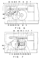
- Figs. 6 and 7 are diagrams, with the essential section taken from the right side view of Fig. 3 and simplified, for easy explanation of the operation.
- a cassette holder 3 for loading and holding a cassette 2 is movably provided between a pair of body frames 1a and 1b of a VTR, for example.
- Drive posts 4a and 4b are secured to both sides of the cassette holder 3 at symmetrical positions.
- Guide rollers are mounted rotatable on these drive posts 4a, 4b.
- the drive posts 4a, 4b are guide to and engaged, via guide rollers 5a and 5b, with L-shaped guide grooves formed symmetrical in a pair of films 1a and 1b.
- a loading motor (hereinafter referred to as FL motor) 7 is secured to one side (1a) of the frame pair 1a, 1b.
- a worm gear 8 coupled to the drive shaft of this FL motor 7 is engaged with a worm wheel 9 supported rotatable on the frame 1a.
- a middle gear 10 is secured coaxial on this worm wheel 9, and is engaged with an arm gear 11a supported rotatable by the frame 1a.
- One end of an arm lever 13a protruding from the arm gear 11a in the radial direction is supported rotatable on a support shaft 12a of the arm gear 11a.
- the aforementioned guide roller 5a is engaged in a slide groove 14a formed in the arm gear 13a in the radial direction.
- a pin 15a is embedded in the proximity of the base section of the arm lever 13a, and is engaged with a groove section 16a formed concentrical in the arm gear 11.
- a pre-load spring 17a which has one end secured to the arm gear 11a, is engaged at the other end with this pin 15a, so that a pre-load will be given to the cassette holder 3 when the cassette 2 is loaded at a predetermined position.
- An arm gear 11b and an arm lever 13b having the same relation with the arm gear 11a and arm lever 13a, are provided on the side of the frame 1b at symmetrical positions.
- the pair of arm gears 11a and 11b will have power transmitted by a shaft 19 through drive gears 18a and 18b, engaged with the arm gears.
- Fig. 6 illustrates the state in which the cassette 2 is at the initial position where it mounted on the cassette holder 3.
- Fig. 7 illustrates the state in which the cassette holder 3 being driven is at the loading position where a tape is pulled from the cassette.
- the slide grooves 16a, 16b formed in the arm levers 13a, 13b have a symmetrical shape.
- the rotation of the FL motor 7 is transmitted to the arm gear 11a on the driven side through the worm gear 8, worm wheel 9 and middle gear 10.
- This rotation of the arm gear 11a is transmitted to the arm lever 13a by making the pin 15b embedded in the arm lever 13a abut on one end of the groove section 16a formed in the arm gear 11a.
- the drive post 4a secured to the cassette holder 3 is moved in the direction of the arrow D via the guide roller 5a engaging the slide groove 14a formed in the arm lever 13 and is guided to the guide groove 6a, thereby moving the cassette holder 3 in the direction of the arrow D.
- the center line B-B on the driven side should be shifted with respect to the center line A-A on the drive side in the cassette unloading direction indicated by the arrow E by the backlash of the aforementioned two pairs of gears 11a, 18a and 11b and 18b.
- the center line B-B will be further delayed at the time of loading the cassette as indicated by the arrow D, as compared with the case where the center lines A-A and are set in phase, and the right and left unbalance tends to increase at the time the cassette is set down or mounted with pressure.
- the center line B-B should be shifted in the direction of the arrow D with respect to the center line A-A by the backlash.
- the parallelism of the right and left of the cassette is deteriorated at the time of unloading the cassette as indicated by the arrow E.
- the center lines of the pair of arm levers do not coincide with each other due to the backlash caused by the engagement of the arm gears with the drive gears. Further, if adjustment is made to set the center lines in phase at the time of loading or unloading the cassette, the phase shift will become greater at the time of the reverse operation.
- Figs. 10 and 11 are side views illustrating in contrast the drive side and driven side of one embodiment of this invention.
- the same reference numerals are given to identical or equivalent sections of the basic example shown in Figs. 1 through 7 25 and Figs. 8 and 9, thereby omitting their description.
- the feature of this embodiment lies in the shapes of slide grooves 14a and 14b formed in the arm levers 13a and 13b, and the other sections are the same as those of the basic example.
- the width Wa of the slide groove 14a formed in the arm lever 13a on the drive side shown in Fig. 11 is greater than the width Wb of the slide groove 14b formed in the arm lever 13b on the driven side.
- the width Wb of the slide groove 14b on the driven side is nearly equal to the diameter of the guide roller 5b, and the width Wa of the slide groove 14a is formed in such a way as to make the amount of the phase shift of the guide rollers 5a, 5b, caused by the backlash resulting from the engagement of the gears 11a, 18a and 11b, 18b, equal to (Wa - Wb).
- the feeding phase shift of the right and left sides of the cassette holder resulting from the backlash between two pairs of gears 11a, 18a and 11b, 18b can be eliminated and the parallelism of the cassette at the slot out time of the cassette can be made equal to the pressure on the right and left of the cassette at the slot down time.
- Figs. 13 and 14 illustrate other embodiments of this invention. According to the embodiment shown in Fig. 13, that portion, indicated by the slant lines, of the peripheral side of a slide groove 14a formed in the arm lever 13a on the drive side on which the guide roller 5a abuts at the unloading time is removed. According to this embodiment, since the phase delay of the guide roller 5a occurs in the operation at the position P8 in Fig. 12, the phase shift can be eliminated.
- the width of drive side one of the slide grooves, which are formed in a pair of arm levers for driving a cassette holder and engaged with drive posts secured to the cassette holder is set greater than that of the driven side slide groove, the phase shift of the right and left of the cassette holder caused by the backlash of the gears that interlockingly drive the pair of arm levers can be eliminated, the cassette holder and cassette can be held in parallel over the entire operational process, and the cassette mounting pressures on the right and left of the cassette at the time of mounting it can be made uniform.
- This invention can be utilized in a system for loading a cassette by front operation, and is particularly suitable as a front loading apparatus in a VTR.
Abstract
Description
- The present invention relates to a cassette loading apparatus for use in a magnetic tape recording/ reproducing apparatus, for example, and more particularly, to a front loading apparatus for loading a cassette from the front side of a video tape recorder (hereinafter referred to as VTR).
- Recently, home VTRs use a front operational type cassette loading apparatus which loads (inserts) a cassette into a VTR at a predetermined position (where a tape is pulled out from the cassette) from the front side for tape recording/reproducing, and unloads (ejects) the cassette to the front side of the VTR after its use is finished.
- Conventionally, this type of front loading apparatus (hereinafter referred to as FL) generally has a power mechanism coupled to a cassette holder for receiving a horizontally loaded cassette. In this case a drive gear is disposed on one side of the cassette holder and a driven gear on the other side. That is, the driven gear interlocks with the drive gear via a transmission mechanism.
- Due to the backlash inevitable to a mechanism using gears, however, the above conventional FL causes a phase shift in view of the operational time between the drive gear and driven gear located at both ends of the cassette holder, at the times of cassette loading and unloading. This deviates the parallelism between the right and left edges of the cassette during operation, so that smooth loading and unloading cannot be provided.
- This invention has been devised to cope with such problem, and aims at providing an FL type cassette loading apparatus which can eliminate a operational phase shift between a cassette holder and the right and left edges of a cassette at the time of loading and unloading the cassette to thereby keep the cassette holder and cassette parallel to each other over the entire operational process.
- To achieve the above object, in a front type cassette loading apparatus comprising a cassette holder for holding a cassette horizontally, drive posts secured symmetrical at both sides of the cassette holder, a pair of arm gears with arm levers having slide grooves formed therein for engagement with the drive posts, an interlocking mechanism for interlocking the arm gears, a drive source for rotationally driving one of the arm gears and a pair of frames, having guide grooves formed therein for engagement with the pair of drive posts, the width of the slide groove formed in that of the pair of arm levers which is located on the drive side is set greater than the width of the slide groove formed in the arm lever on the driven side.
- The aforementioned object of this invention and other objects and features will become apparent in the following description of some embodiments given referring to the accompanying drawings in which:
- Figs. 1 through 9 illustrate the basic example of a cassette loading apparatus according to this invention, Fig. 1 being an external perspective view of a front loading apparatus,
- Figs. 2 to 5 being a top view, a right side view, a left side view and a front view, respectively, Figs. 6 and 7 being diagrams, with the essential section taken from the right side view of Fig. 3 and simplified, for easy explanation of the operation, and
- Figs. 8 and 9 being diagrams, with the essential sections taken from the right side view of Fig. 3 and the left side view of Fig. 4 and simplified, for easy explanation of the operation;
- Figs. 10 and 11 are side views illustrating the drive side and driven side of a cassette loading apparatus according to one embodiment of this invention;
- Fig. 12 is a diagram illustrating the operation of the same embodiment;
- Figs. 13 and 14 are plan views illustrating slide grooves according to other embodiments of this invention; and
- Figs. 15 and 16 are detailed diagrams of the essential sections of Figs. 10 and 11.
- First, a description will be given of the basic example of an FL type cassette loading apparatus according to this invention.
- This FL type cassette loading apparatus is structured as illustrated in Figs. 1 through 7. Fig. 1 is an external perspective view, and Figs. 2 to 5 are a top view, a right side view, a left side view and a front view, respectively. Figs. 6 and 7 are diagrams, with the essential section taken from the right side view of Fig. 3 and simplified, for easy explanation of the operation.
- The following describes only those common in the individual diagrams and essential to this invention.
- Referring to the individual diagrams, a
cassette holder 3 for loading and holding acassette 2 is movably provided between a pair ofbody frames 1a and 1b of a VTR, for example.Drive posts 4a and 4b are secured to both sides of thecassette holder 3 at symmetrical positions. Guide rollers are mounted rotatable on thesedrive posts 4a, 4b. Thedrive posts 4a, 4b are guide to and engaged, viaguide rollers films 1a and 1b. A loading motor (hereinafter referred to as FL motor) 7 is secured to one side (1a) of theframe pair 1a, 1b. Aworm gear 8 coupled to the drive shaft of thisFL motor 7 is engaged with aworm wheel 9 supported rotatable on theframe 1a. Amiddle gear 10 is secured coaxial on thisworm wheel 9, and is engaged with an arm gear 11a supported rotatable by theframe 1a. One end of anarm lever 13a protruding from the arm gear 11a in the radial direction is supported rotatable on a support shaft 12a of the arm gear 11a. Theaforementioned guide roller 5a is engaged in a slide groove 14a formed in thearm gear 13a in the radial direction. A pin 15a is embedded in the proximity of the base section of thearm lever 13a, and is engaged with agroove section 16a formed concentrical in the arm gear 11. A pre-load spring 17a, which has one end secured to the arm gear 11a, is engaged at the other end with this pin 15a, so that a pre-load will be given to thecassette holder 3 when thecassette 2 is loaded at a predetermined position. Anarm gear 11b and anarm lever 13b, having the same relation with the arm gear 11a andarm lever 13a, are provided on the side of the frame 1b at symmetrical positions. The pair ofarm gears 11a and 11b will have power transmitted by ashaft 19 throughdrive gears 18a and 18b, engaged with the arm gears. Fig. 6 illustrates the state in which thecassette 2 is at the initial position where it mounted on thecassette holder 3. Fig. 7 illustrates the state in which thecassette holder 3 being driven is at the loading position where a tape is pulled from the cassette. In this basic example, theslide grooves arm levers - The operation of the FL constructed as above will be described referring to Figs. 8 and 9. As shown in Fig. 8, the rotation of the
FL motor 7 is transmitted to the arm gear 11a on the driven side through theworm gear 8,worm wheel 9 andmiddle gear 10. This rotation of the arm gear 11a is transmitted to thearm lever 13a by making thepin 15b embedded in thearm lever 13a abut on one end of thegroove section 16a formed in the arm gear 11a. Further, the drive post 4a secured to thecassette holder 3 is moved in the direction of the arrow D via theguide roller 5a engaging the slide groove 14a formed in the arm lever 13 and is guided to theguide groove 6a, thereby moving thecassette holder 3 in the direction of the arrow D. Meanwhile, power is transmitted to thearm gear 11b on the driven side shown in Fig. 9 through the drive gear 18a engaged with the arm gear 11a on the drive side, theshaft 19 and the drive gear18b engaged with thearm gear 11b on the driven side, and thecassette holder 3 will be moved in the same manner. - If the improvement of this invention as described later is not made in such an operation, however, there exists a backlash between the
arm gears 11a, 11b anddrive gears 18a, 18b on the drive and driven sides. This causes a phase shift between the center lines A-A and B-B respectively connecting the centers of the right andleft arm gears 11a, 11b to thedrive posts 4. Since the pair ofguide rollers guide roller 5b on the driven side always moves later than theguide roller 5a on the drive side at the operation time even if the center lines A-A and B-B are first set in phase. - In order to provide the parallelism of the right and left of the cassette when unloading it, the center line B-B on the driven side should be shifted with respect to the center line A-A on the drive side in the cassette unloading direction indicated by the arrow E by the backlash of the aforementioned two pairs of
gears - As described above, according to the FL of the basic example, when the pair of arm gears are rotated interlockingly via the drive gears and the cassette holder is moved by the arm levers that rotate together with the arm gears, the center lines of the pair of arm levers do not coincide with each other due to the backlash caused by the engagement of the arm gears with the drive gears. Further, if adjustment is made to set the center lines in phase at the time of loading or unloading the cassette, the phase shift will become greater at the time of the reverse operation.
- Referring to the diagrams, a description will now be given of an FL type cassette loading apparatus according to one embodiment of this invention which solves the above problems.
- Figs. 10 and 11 are side views illustrating in contrast the drive side and driven side of one embodiment of this invention. In these diagrams, the same reference numerals are given to identical or equivalent sections of the basic example shown in Figs. 1 through 7 25 and Figs. 8 and 9, thereby omitting their description. The feature of this embodiment lies in the shapes of
slide grooves 14a and 14b formed in the arm levers 13a and 13b, and the other sections are the same as those of the basic example. The width Wa of the slide groove 14a formed in thearm lever 13a on the drive side shown in Fig. 11 is greater than the width Wb of theslide groove 14b formed in thearm lever 13b on the driven side. The width Wb of theslide groove 14b on the driven side is nearly equal to the diameter of theguide roller 5b, and the width Wa of the slide groove 14a is formed in such a way as to make the amount of the phase shift of theguide rollers gears - The operation of the present embodiment will be described referring to Fig. 12. As the
guide roller 5b on the driven side is engaged almost without a gap, with theslide groove 14b formed in thearm lever 13b on the driven side, the phase of theguide roller 5b always coincides with the center line B-B of thearm lever 13b. Assume that theguide rollers cassette 2 is mounted to and detached from thecassette holder 3, the loading positions P₄ and P₅ where the tape is pulled out from the cassette, and the middle positions P₂, P₃, P₆ and P₇ there between. In the operation at P₁, since theguide rollers arm lever 13a on the drive side. Since theguide roller 5a is also at the phase delay position with respect to the center line A-A of thearm lever 13a, however, the center line A-A coincides with the center line B-B of thearm lever 13b on the driven side. The same applies to the operations at the positions P₃ to P₇. In the operation at P₈, theguide roller 5a on the drive side tends to be slightly advancing; however, this does not raise any problem in consideration of the safety of the cassette holder in slot out status. - According to this embodiment, the feeding phase shift of the right and left sides of the cassette holder resulting from the backlash between two pairs of
gears - Figs. 13 and 14 illustrate other embodiments of this invention. According to the embodiment shown in Fig. 13, that portion, indicated by the slant lines, of the peripheral side of a slide groove 14a formed in the
arm lever 13a on the drive side on which theguide roller 5a abuts at the unloading time is removed. According to this embodiment, since the phase delay of theguide roller 5a occurs in the operation at the position P₈ in Fig. 12, the phase shift can be eliminated. - According to the embodiment shown in Fig. 14, that portion, indicated by the slant lines, of the peripheral side of a slide groove 14a formed in the
arm lever 13a on the drive side on which theguide roller 5a abuts at the loading time is removed. According to this embodiment, it is possible to eliminate the phase shift caused in a case where thecassette 2 is driven from the beginning at the position P₁ in Fig. 13. - Although the foregoing description has been given with reference to the arm gear 11a on the drive side being directly engaged with the drive gear 18a, the engagement is actually made via an
intermediate gear 20 as shown in Fig. 15. The arm gear 11a on the drive side has a smaller diameter than thearm gear 11b on the driven side shown in Fig. 16 by the intervention of theintermediate gear 20. These contribute to providing synchronization of the right and left ends of thecassette holder 3. - As describe above, according to this invention, since the width of drive side one of the slide grooves, which are formed in a pair of arm levers for driving a cassette holder and engaged with drive posts secured to the cassette holder, is set greater than that of the driven side slide groove, the phase shift of the right and left of the cassette holder caused by the backlash of the gears that interlockingly drive the pair of arm levers can be eliminated, the cassette holder and cassette can be held in parallel over the entire operational process, and the cassette mounting pressures on the right and left of the cassette at the time of mounting it can be made uniform.
- This invention can be utilized in a system for loading a cassette by front operation, and is particularly suitable as a front loading apparatus in a VTR.
Claims (3)
- A cassette loading apparatus comprising:
a cassette holder for holding a cassette horizontally;
drive posts secured symmetrical at both sides of said cassette holder;
a pair of arm gears with arm levers having slide grooves formed therein for engagement with said drive posts;
an interlocking mechanism for interlocking said arm gears; and
a drive source for rotationally driving one of said arm gears and a pair of frames, having guide grooves formed therein for engagement with said pair of drive posts, characterized in that
the width of said slide groove formed in that of said pair of arm levers which is located on said drive side is set greater than the width of said slide groove formed in said arm lever on said driven side. - A cassette loading apparatus according to claim 1, characterized in that portion of a peripheral side of said slide groove formed in said arm lever on said drive side on which said drive post abuts at an unloading time is removed.
- A cassette loading apparatus according to claim 1, characterized in that portion of a peripheral side of said slide groove formed in said arm lever on said drive side on which said drive post abuts at a loading time is removed.
Applications Claiming Priority (3)
| Application Number | Priority Date | Filing Date | Title |
|---|---|---|---|
| JP62283014A JPH01125756A (en) | 1987-11-11 | 1987-11-11 | Front loading device |
| JP283014/87 | 1987-11-11 | ||
| PCT/JP1988/001134 WO1989004538A1 (en) | 1987-11-11 | 1988-11-11 | Cassette loading apparatus |
Publications (3)
| Publication Number | Publication Date |
|---|---|
| EP0440793A1 true EP0440793A1 (en) | 1991-08-14 |
| EP0440793A4 EP0440793A4 (en) | 1992-02-26 |
| EP0440793B1 EP0440793B1 (en) | 1994-08-17 |
Family
ID=17660108
Family Applications (1)
| Application Number | Title | Priority Date | Filing Date |
|---|---|---|---|
| EP88909827A Expired - Lifetime EP0440793B1 (en) | 1987-11-11 | 1988-11-11 | Cassette loading apparatus |
Country Status (6)
| Country | Link |
|---|---|
| US (1) | US5034834A (en) |
| EP (1) | EP0440793B1 (en) |
| JP (1) | JPH01125756A (en) |
| KR (1) | KR930001102B1 (en) |
| DE (1) | DE3851156T2 (en) |
| WO (1) | WO1989004538A1 (en) |
Families Citing this family (3)
| Publication number | Priority date | Publication date | Assignee | Title |
|---|---|---|---|---|
| KR940000860Y1 (en) * | 1991-06-24 | 1994-02-18 | 섬성전자 주식회사 | Tape loading apparatus for vtr |
| JPH0744967A (en) * | 1993-07-30 | 1995-02-14 | Olympus Optical Co Ltd | Loading/ejecting mechanism for recording medium |
| JP4922384B2 (en) * | 2009-12-08 | 2012-04-25 | 関東自動車工業株式会社 | Car seat belt equipment |
Citations (2)
| Publication number | Priority date | Publication date | Assignee | Title |
|---|---|---|---|---|
| US4319292A (en) * | 1978-12-28 | 1982-03-09 | Victor Company Of Japan, Ltd. | Cassette loading and ejecting apparatus |
| JPS6364666A (en) * | 1986-09-05 | 1988-03-23 | Matsushita Electric Ind Co Ltd | Cassette loader |
Family Cites Families (6)
| Publication number | Priority date | Publication date | Assignee | Title |
|---|---|---|---|---|
| DE3235835A1 (en) * | 1982-09-28 | 1984-03-29 | Siemens AG, 1000 Berlin und 8000 München | SEMICONDUCTOR STORAGE CELL |
| JPS61130057A (en) * | 1984-11-30 | 1986-06-17 | Mita Ind Co Ltd | Electrostatic image output device |
| JPH0619885B2 (en) * | 1984-12-20 | 1994-03-16 | 三洋電機株式会社 | Cassette loading mechanism |
| JPH0627388B2 (en) * | 1985-09-07 | 1994-04-13 | 株式会社豊田自動織機製作所 | Rough bobbin improper mating detection device |
| EP0260437B1 (en) * | 1986-08-19 | 1991-03-06 | Matsushita Electric Industrial Co., Ltd. | Cassette loading apparatus |
| JPS6349643A (en) * | 1986-08-20 | 1988-03-02 | Matsushita Seiko Co Ltd | Air conditioner |
-
1987
- 1987-11-11 JP JP62283014A patent/JPH01125756A/en active Pending
-
1988
- 1988-11-07 KR KR1019880014585A patent/KR930001102B1/en not_active IP Right Cessation
- 1988-11-11 EP EP88909827A patent/EP0440793B1/en not_active Expired - Lifetime
- 1988-11-11 DE DE3851156T patent/DE3851156T2/en not_active Expired - Fee Related
- 1988-11-11 WO PCT/JP1988/001134 patent/WO1989004538A1/en active IP Right Grant
- 1988-11-11 US US07/392,989 patent/US5034834A/en not_active Expired - Fee Related
Patent Citations (2)
| Publication number | Priority date | Publication date | Assignee | Title |
|---|---|---|---|---|
| US4319292A (en) * | 1978-12-28 | 1982-03-09 | Victor Company Of Japan, Ltd. | Cassette loading and ejecting apparatus |
| JPS6364666A (en) * | 1986-09-05 | 1988-03-23 | Matsushita Electric Ind Co Ltd | Cassette loader |
Non-Patent Citations (2)
| Title |
|---|
| PATENT ABSTRACTS OF JAPAN vol. 12, no. 288 (P-741)(3135) 8 August 1988 & JP-A-63 064 666 ( MATSUSHITA ELECTRIC IND. CO. LTD. ) 23 March 1988 * |
| See also references of WO8904538A1 * |
Also Published As
| Publication number | Publication date |
|---|---|
| DE3851156D1 (en) | 1994-09-22 |
| EP0440793B1 (en) | 1994-08-17 |
| KR930001102B1 (en) | 1993-02-15 |
| DE3851156T2 (en) | 1995-01-12 |
| WO1989004538A1 (en) | 1989-05-18 |
| US5034834A (en) | 1991-07-23 |
| KR890008785A (en) | 1989-07-12 |
| EP0440793A4 (en) | 1992-02-26 |
| JPH01125756A (en) | 1989-05-18 |
Similar Documents
| Publication | Publication Date | Title |
|---|---|---|
| US4701899A (en) | Swinging record changer | |
| US4879615A (en) | Cartridge transfer mechanism for a disk file apparatus | |
| JPS61187156A (en) | Tape recorder | |
| US4868693A (en) | Magnetic recording and/or reproducing apparatus | |
| EP0440793B1 (en) | Cassette loading apparatus | |
| US4752845A (en) | Positive motion cam mechanism for performing tape loading functions in cassette tape recorder | |
| US4527264A (en) | Compact disc loading and unloading device with rotationally actuated movable disc support | |
| US4191979A (en) | Device for extracting and positioning video tape from a cassette to around a slit head drum | |
| US4803574A (en) | Arrangement of recording and/or reproducing apparatus | |
| EP0628961A2 (en) | A tape tensioning mechanism | |
| US4734800A (en) | Changeover mechanism for selectively driving tape loading and cassette loading in a tape recorder | |
| US4757398A (en) | Tape withdrawing device for a magnetic recording and/or reproducing apparatus | |
| EP0412808B1 (en) | Tape cartridge loading/unloading apparatus | |
| US4731684A (en) | Pivotable changeover mechanism for loading and ejecting functions in cassette tape recorder | |
| US5381283A (en) | Tape loading apparatus | |
| KR100207688B1 (en) | Deck mechanism of tape recorder | |
| US4918547A (en) | Door opening and closing mechanism for an automatic charger for recording media | |
| GB1475388A (en) | Recording and/or reproducing apparatus and record assembly for use therein | |
| US5041930A (en) | Apparatus having a single capstan motor for recording/reproducing data on a magnetic tape | |
| JPH0762932B2 (en) | Cassette and tape processing equipment | |
| US5031057A (en) | Tape moving mechanism for automatic time cassette changer | |
| JPH04268247A (en) | Device and for method carrying disk cartridge | |
| US6076415A (en) | Bi-directional, dual speed film transport gear drive apparatus with an open loop control gear mesh routine | |
| JP2537974B2 (en) | Cassette loading device | |
| JPH0695418B2 (en) | Cassette type recording / reproducing device |
Legal Events
| Date | Code | Title | Description |
|---|---|---|---|
| PUAI | Public reference made under article 153(3) epc to a published international application that has entered the european phase |
Free format text: ORIGINAL CODE: 0009012 |
|
| 17P | Request for examination filed |
Effective date: 19890803 |
|
| AK | Designated contracting states |
Kind code of ref document: A1 Designated state(s): DE FR GB |
|
| A4 | Supplementary search report drawn up and despatched |
Effective date: 19920106 |
|
| AK | Designated contracting states |
Kind code of ref document: A4 Designated state(s): DE FR GB |
|
| RAP1 | Party data changed (applicant data changed or rights of an application transferred) |
Owner name: TOSHIBA AVE CO., LTD Owner name: KABUSHIKI KAISHA TOSHIBA |
|
| 17Q | First examination report despatched |
Effective date: 19931021 |
|
| GRAA | (expected) grant |
Free format text: ORIGINAL CODE: 0009210 |
|
| AK | Designated contracting states |
Kind code of ref document: B1 Designated state(s): DE FR GB |
|
| REF | Corresponds to: |
Ref document number: 3851156 Country of ref document: DE Date of ref document: 19940922 |
|
| ET | Fr: translation filed | ||
| PLBE | No opposition filed within time limit |
Free format text: ORIGINAL CODE: 0009261 |
|
| STAA | Information on the status of an ep patent application or granted ep patent |
Free format text: STATUS: NO OPPOSITION FILED WITHIN TIME LIMIT |
|
| 26N | No opposition filed | ||
| PGFP | Annual fee paid to national office [announced via postgrant information from national office to epo] |
Ref country code: GB Payment date: 19961104 Year of fee payment: 9 |
|
| PGFP | Annual fee paid to national office [announced via postgrant information from national office to epo] |
Ref country code: FR Payment date: 19961111 Year of fee payment: 9 |
|
| PGFP | Annual fee paid to national office [announced via postgrant information from national office to epo] |
Ref country code: DE Payment date: 19961115 Year of fee payment: 9 |
|
| PG25 | Lapsed in a contracting state [announced via postgrant information from national office to epo] |
Ref country code: GB Free format text: LAPSE BECAUSE OF NON-PAYMENT OF DUE FEES Effective date: 19971111 |
|
| PG25 | Lapsed in a contracting state [announced via postgrant information from national office to epo] |
Ref country code: FR Free format text: THE PATENT HAS BEEN ANNULLED BY A DECISION OF A NATIONAL AUTHORITY Effective date: 19971130 |
|
| GBPC | Gb: european patent ceased through non-payment of renewal fee |
Effective date: 19971111 |
|
| PG25 | Lapsed in a contracting state [announced via postgrant information from national office to epo] |
Ref country code: DE Free format text: LAPSE BECAUSE OF NON-PAYMENT OF DUE FEES Effective date: 19980801 |
|
| REG | Reference to a national code |
Ref country code: FR Ref legal event code: ST |