EP0440113B1 - Jet road of high convection gas for plate-like materials transported by rolls - Google Patents
Jet road of high convection gas for plate-like materials transported by rolls Download PDFInfo
- Publication number
- EP0440113B1 EP0440113B1 EP91100999A EP91100999A EP0440113B1 EP 0440113 B1 EP0440113 B1 EP 0440113B1 EP 91100999 A EP91100999 A EP 91100999A EP 91100999 A EP91100999 A EP 91100999A EP 0440113 B1 EP0440113 B1 EP 0440113B1
- Authority
- EP
- European Patent Office
- Prior art keywords
- nozzle
- ribs
- set forth
- gas jet
- jet section
- Prior art date
- Legal status (The legal status is an assumption and is not a legal conclusion. Google has not performed a legal analysis and makes no representation as to the accuracy of the status listed.)
- Expired - Lifetime
Links
Images


Classifications
-
- C—CHEMISTRY; METALLURGY
- C03—GLASS; MINERAL OR SLAG WOOL
- C03B—MANUFACTURE, SHAPING, OR SUPPLEMENTARY PROCESSES
- C03B27/00—Tempering or quenching glass products
- C03B27/04—Tempering or quenching glass products using gas
- C03B27/0404—Nozzles, blow heads, blowing units or their arrangements, specially adapted for flat or bent glass sheets
-
- C—CHEMISTRY; METALLURGY
- C03—GLASS; MINERAL OR SLAG WOOL
- C03B—MANUFACTURE, SHAPING, OR SUPPLEMENTARY PROCESSES
- C03B27/00—Tempering or quenching glass products
- C03B27/04—Tempering or quenching glass products using gas
- C03B27/0417—Controlling or regulating for flat or bent glass sheets
-
- C—CHEMISTRY; METALLURGY
- C03—GLASS; MINERAL OR SLAG WOOL
- C03B—MANUFACTURE, SHAPING, OR SUPPLEMENTARY PROCESSES
- C03B27/00—Tempering or quenching glass products
- C03B27/04—Tempering or quenching glass products using gas
- C03B27/044—Tempering or quenching glass products using gas for flat or bent glass sheets being in a horizontal position
-
- C—CHEMISTRY; METALLURGY
- C03—GLASS; MINERAL OR SLAG WOOL
- C03B—MANUFACTURE, SHAPING, OR SUPPLEMENTARY PROCESSES
- C03B40/00—Preventing adhesion between glass and glass or between glass and the means used to shape it, hold it or support it
- C03B40/005—Fabrics, felts or loose covers
Definitions
- the invention relates to a high-convection gas jet nozzle section for flat material guided over rollers, in particular for the thermal tempering of thin flat glass panes, with a lower nozzle array with centrically and parallel to one another or to the rollers between the rollers, provided with nozzle openings, and with one Upper nozzle field, the nozzle ribs provided with nozzle openings are arranged symmetrically to the vertical axis of the opposite, lower nozzle ribs.
- Such high-convection gas jet nozzle sections can be used to heat or cool the sheet-like material guided over rollers, for example a metal plate, a band of metal, plastic, fibers, textiles, and sections of such materials.
- the heat transfer coefficient to be achieved in a cooling section for the thermal tempering of glass is approximately inversely proportional to the glass thickness.
- the heat transfer is usually achieved by blowing the glass pane heated to its softening temperature with air from a nozzle system which is supplied by a fan.
- the heat transfer coefficient only increases with the 0.7th power of the nozzle outlet speed.
- the flow rate required for this increases with the third power of the nozzle outlet speed. So for example tempered in a cooling section of glass with a thickness of 3 mm instead of a thickness of 5 mm, the nozzle outlet speed would have to be increased approximately 2.1 times and the flow rate by 9 times in order to achieve the same heat transfer .
- such an increase in performance is the usual way of expanding the area of application of a cooling section for tempering glass to thin glass thicknesses.
- nozzle pressures of 20,000 to 22,000 pa are used in industrially operated cooling sections to temper flat 3 mm thick glass panes.
- the pressure on the underside must be increased compared to the pressure on the top of the disc in order to compensate for the heat transfer difference caused thereby.
- this pressure difference can be compensated for by the comparatively high weight of the disk so that, despite a pressure difference, there is still sufficient guidance of the disk through the rollers.
- the significantly higher nozzle pressure required on the underside leads to this generated, from bottom to top pressure differential force to lift the panes from the roller hearth and thus to significant production problems, if the tempering of thin glass is possible with such a system.
- roll dummies e.g. B. cylindrical tubes are used, which produce a similar accumulation effect for the bias air applied to the disc, as is caused by the rollers below the disc.
- these dummy rolls unlike the rollers, do not touch the surface of the pane, but must be kept at a certain minimum distance above the glass surface, the flow field and consequently also the pressure field differ, and with it, ultimately, the heat transfer at the top and on the underside of the glass pane is so considerable that a pane safety glass with a thickness of less than 3.2 mm can be produced with such systems only with considerable restrictions with regard to the requirements for the optical quality and the fracture pattern.
- the nozzle system without exception, it generates rays that hit the web at an angle; the blow-out direction of each row of nozzle holes, starting from the center of the nozzle box and relative to the web, is arranged from row of holes to row of holes in each case at a lower blow-out angle; in addition, the clear distance from the web is progressively larger for each row of nozzle holes - progressively progressing from the center of the nozzle box to the two edges of the nozzle box - than in the previous row of nozzle holes.
- This nozzle which was developed for drying technology, is specially designed so that thin, relatively sensitive webs of material to be dried cannot stand out from the surface on which they are guided. A beam angle of 15 ° to 45 ° can therefore also be accepted. With such large beam inclination angles, however, it is not possible to generate the extremely high heat transfer that is required, for example, for toughening thin safety glass panes.
- the invention has for its object to provide a high convection gas jet nozzle section of the type specified in which the above-mentioned disadvantages do not occur.
- a nozzle section is to be proposed in which the same heat transfer and the same pressurization result on the top and on the bottom of the material even without the use of roller dummy.
- the nozzle bottoms of the upper nozzle ribs have the cross section of a letter "M" extended by a median strip, that the width of the nozzle bottoms of the upper nozzle ribs is greater than the horizontal distance between the rollers and smaller than the roller pitch that the median strip and the two inner legs of the expanded M cross section of the nozzle bottoms which are folded upward are provided with nozzle openings, and that the smallest distance between the upper nozzle ribs and the top of the product is greater than the smallest distance between the lower nozzle ribs and the underside of the product.
- the advantages achieved by the invention are based on the fact that the desired high heat transfer is achieved by a nozzle field which is considerably finer and more delicate compared to conventional pre-stressing nozzle systems while the entire glass surface is applied as uniformly as possible.
- the nozzle ribs on the top of the goods are shaped such that they produce the same heat transfer and the same pressure on the goods as the nozzle ribs provided on the underside of the goods, their flow behavior and ultimately also the heat transfer influenced by the rollers arranged between them becomes.
- This uniform heat transfer on the top and bottom of the goods is achieved in that the jet streams all strike the surface of the goods at approximately the same arrival speed.
- inclined beams the beam path of which is larger up to the point of impact on the surface of the material, must be provided with a larger diameter. This larger diameter and the associated larger volume flow make it necessary to change the nozzle pitch for these larger diameter jet streams.
- the jamming effect of the rollers on the underside of the goods is compensated for by the shape of the nozzle ribs on the top of the goods without having to use the otherwise usual roller dummy on the top of the goods.
- the downward-facing, outer legs of the M-shaped cross section of the nozzle bottoms of the upper nozzle ribs contribute to this, narrowing the outflow area for the gas escaping from the nozzle bores of the upper nozzle ribs on both sides of the upper nozzle ribs and thereby for a defined impact pattern on the upper side care of the good.
- Fig. 1 shows a longitudinal section of a section of a high convection gas jet nozzle section as a cooling and thus tempering section for flat glass panes 7 guided over rollers 1.
- the nozzle ribs 2a of the lower nozzle array 2 are arranged between the rollers 1; H. these nozzle ribs 2a of the lower nozzle field 2 blow the free underside of the glass pane 7 between the rollers 1.
- the nozzle ribs 3b of the upper nozzle array 3, which blow on the upper side of the glass pane 7, are arranged exactly above the lower nozzle ribs 2a.
- the distance of the lower nozzle ribs 2a from the glass surface is preferably between 4 mm and 12 mm, while the distance of the upper nozzle ribs 3b from the surface of the glass can be approximately twice as large, that is to say should be in the range between 8 mm and 24 mm.
- the rollers 1 have the core shown in the drawing, usually a metal core or a metal tube, which is wrapped ("bandaged") with a band of a material that withstands the comparatively high temperature of the glass pane 7. That comes as a material, for example aromatic polyamide sold under the trademark "Kevlar”, but also other high-temperature resistant materials from which strips or tapes can be produced.
- the solid cores of the rollers 1 can also be provided with rings.
- rings In particular, the mounting of O-rings from the fluororubbers marketed under the name "Viton" or the use of rings made of silicate fiber material, for example calcium silicate fiber material, has proven successful.
- nozzle cap shape with a parallel to the transport plane central area 2a1, on each side of which a beveled area 2a2 connects ("hipped roof").
- the size of the nozzle openings is distributed over the three areas, the largest nozzle openings 2b being located at the outer edge of the chamfered areas 2a2; As can be seen in FIG. 2, a row of nozzle openings 2b with a relatively large diameter is arranged in this edge region.
- the next, inward row of nozzle openings 2c has a smaller diameter, while in the central region 2a1 there are only nozzle openings 2c with the smallest diameter of the three different nozzle opening sizes.
- the side view of the nozzle bottom of the upper nozzle ribs 3b has the shape of an elongated letter "M" with an additional central strip 4a; starting from this median strip 4a, which runs approximately parallel to the transport plane of the glass pane 7, the two adjoining legs 4b1 and 4b2 of the nozzle base 4 extend somewhat upwards to the edge at which the nozzle base is closed by downward-pointing, outer legs 4c. These legs 4c narrow the outflow area for the gas emerging from the nozzle bores of the upper nozzle ribs 3b on both sides of the upper nozzle ribs 3b, so that the gas flowing back is deflected there, as indicated by the flow arrows in FIG. 1.
- nozzle openings 4d there is a row of nozzle openings 4d with the largest diameter of all nozzle openings in the upper nozzle ribs 3b in the chamfered areas 4b1 and 4b2, and approximately in the middle of these areas.
- a second row of nozzle openings 4e with a smaller diameter is located on the inner edge of the chamfered areas 4b1 or 4b2, while nozzle openings 4f with the smallest diameter are formed in the median strip 4a.
- FIG. 1 also shows the jet directions of the gas jets emerging from the various nozzle openings; It can be seen that the gas jets emerging from the respective central regions of the nozzle ribs strike the glass pane 7 approximately perpendicularly, while the gas jets coming from the edge regions are inclined to different degrees, namely the gas jets coming from the lower nozzle ribs 2a more than those from the lateral ones Legs of the upper nozzle ribs 3b coming gas jets.
- the nozzle ribs are not designed as a welded construction from one piece, but rather the nozzle caps 2d of the lower nozzle ribs 2a are slidably attached to the base parts 2f of the nozzle ribs 2a with the aid of the screw connection 2e shown in FIG. 1, so that manufacturing inaccuracies can still be compensated for; this contributes to the fact that the exposure images of the upper nozzle field 3 and the lower nozzle field 2 can be brought very closely to cover.
- FIG. 2 A development of those surfaces of the nozzle ribs 2a or 2b in which the nozzle openings are formed, namely the nozzle bottoms 4 on the one hand and the nozzle caps 2d on the other hand, can be seen in FIG. 2. It can be seen that the diameter of the nozzle openings 2b, 2c and 2d or 4d, 4e and 4f and the division of the rows of nozzle openings each from the Increase outwards in the middle of a nozzle rib. The inner rows of nozzle openings are each offset by half a division. The division of the outer rows of nozzle openings is chosen larger in accordance with the larger diameter of the nozzle openings due to the larger jet path.
- the distance between the individual rows of nozzle openings is greater for the nozzle bottom 4 of the upper nozzle rib 3b shown on the left in FIG. 2, in accordance with the shape of the nozzle bottom different from the lower nozzle rib 2a, than for the lower nozzle rib 2a.
- the width of the nozzle bottom 4 of the upper nozzle ribs 3b is greater than the horizontal distance between the rollers 1 and smaller than the roller pitch, so that the downward legs 4b1 and 4b2 are above the rollers 1 , while the central areas 2a1 and 4a of the respective nozzle bottoms are directly opposite one another.
- the smallest distance of the upper nozzle ribs 3b from the top of the glass pane, indicated by the reference symbol 5 in FIG. 1, is greater than the smallest distance of the lower nozzle ribs 2e from the underside of the glass pane 7, indicated by the reference symbol 6 in FIG. 1.
- the following dimensions should be used for the nozzle ribs 2a and 3b:
- the width BP of the essentially flat central strip 4a of the upper nozzle bottoms 4 should lie within the following limits: 0.5 BU ⁇ BP ⁇ 0.75 BU
- the edging angle of the two legs 4b1 and 4b2 of the upper nozzle bases 4, that is, the angle at which the two legs 4b1 and 4b2 extend from the horizontal median strip 4a upwards, should be in the range from 5 ° to 10 °.
- the width BK of the two inner flared legs 4b1 and 4b2 of the nozzle bottoms 4 of the upper nozzle ribs 3b should be within the following limits: 0.6 BU ⁇ BK ⁇ 0.9 BU.
- the inclination of the two downward bent outer legs 4c of the nozzle bases 4 of the upper nozzle ribs 3b against the horizontal should be between 40 ° and 50 °, in particular approximately 45 °.
- the width BR of the two outer legs of the nozzle bottoms 4 bent downward should be within the following limits: 0.1 BU ⁇ BR ⁇ 0.25 BU.
- the flat central strip 4a of the upper nozzle bases 4 has an odd number of rows of nozzle openings 4f with comparatively small hole divisions; the rows of nozzle openings are spaced from one another by approximately one hole pitch and are offset from one another in the longitudinal direction by half the hole pitch.
- the upwardly inclined areas 4b1 and 4b2 of the nozzle bases 4 have further rows of nozzle openings with a larger diameter and with a larger hole division, the diameter and / or the hole division increasing with the atomic number of the rows of nozzle openings from the inside to the outside.
- the middle strips 4a of the upper nozzle bases 4 have three rows of nozzle openings and the two adjacent, upwardly inclined regions 4b 1 and 4b 2 each have two rows of nozzle openings with the double hole division.
- the width BP of the central strip 4a is 0.67 times the total width BU of the lower nozzle ribs 2a; the edging angle of the two legs 4b1 and 4b2 is 8 °; the width BK of the two legs 4b1 and 4b2 is 0.8 times the total width BU; and the width BR corresponds to 0.14 times the total width BU.
- the upper nozzle bases 4 have a central strip 4a with three rows of nozzle openings 4f and adjacent, upwardly inclined legs 4b1 and 4b2, each with two rows of nozzle openings 4d and 4e, each with a decreasing diameter and with the double hole pitch.
- an exposure image can be generated on the underside of the glass pane 7, which is a mirror image of that on the upper side of the glass pane 7.
- the geometric exit area of the nozzle openings which is one-sided with respect to the blown area, is approximately 2% to approximately 5%; the exit area of the nozzle openings for the upper and lower nozzle ribs 3b and 2a should be the same.
- the pitch of rollers 1 and nozzle ribs 2a and 3b should be in the range from 60 mm to 150 mm.
- the nozzle caps 2d of the lower nozzle ribs 2a are chamfered in the manner of a hipped roof and screwed to the base part 2f (2e), both the horizontal central region 2a1 and the two chamfered edge regions 2a2 having nozzle openings .
- FIG. 3 A cross-section through a high-convection gas jet nozzle section for the thermal tempering of flat glass panes is shown in FIG. 3. Particularly in the case of larger working widths, it is expedient to supply the upper and lower nozzle ribs 3b and 2a via air channels 18o and 18u so that the air heated by the glass surface is without Obstruction can flow vertically upward from the glass sheet between the respective nozzle ribs 2a and 3b.
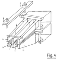
- This large free space for outflow of the air blown onto the glass pane 7 for cooling is also shown in the perspective illustration according to FIG. 4, in which the corresponding flow arrows are entered.
- the upper nozzle hearth 19o or its nozzle ribs 3b are pivotally mounted on a frame 11 about an axis of rotation 10.
- the height of the frame 11 can be finely adjusted by means of lifting elements 12 which are fastened to a stationary frame and are actuated by spindles, which are indicated in FIG. 3 by the rotating arrows, by means of an electric motor 13.
- the entire upper nozzle range 3 can be swiveled out rapidly about the axis of rotation 10 by means of a compressed air cylinder 14.
- This double-acting compressed air cylinder 14 causes this pivoting movement during normal operation of the nozzle hearth.
- a special locking mechanism can also be provided, which is triggered by the lifting movement of the compressed air cylinder 14. Such locking is particularly useful when the nozzle section must be operated at high pressures.
- the lower nozzle hearth 19u or nozzle ribs 2a is pivoted away by means of a compressed air cylinder 17 about a swivel joint 15 possible, which is also designed to be adjustable in height, as indicated by the double arrow in FIG. 3.
- a swivel joint 15 which is also designed to be adjustable in height, as indicated by the double arrow in FIG. 3.
- only a fine adjustment of the height by means of a stop 16 and the height-adjustable swivel joint 15 is necessary, since the distance of the lower nozzles from the underside of the glass pane 7 depends only on the position of the lower nozzle ribs 2a with respect to the rollers 1 and for all glass thicknesses is equal to.
- the route shown in FIG. 3 is suitable for automation if appropriate computer-controlled motors and displacement sensors are installed.
- the distance 5.6 of the upper nozzle field 19o and the lower nozzle field 19u from the roller hearth surface can be set in the manner described depending on the respective operating condition requirements. As a rule, it can be assumed that the distance of the upper nozzle ribs 3b from the top of the glass pane 7 should be approximately twice as large as the distance of the lower nozzle ribs 2a from the underside of the glass pane.
- thermally toughened single-pane safety glass is, in addition to the satisfactory appearance, guaranteed by good flatness and a damage-free surface, also the achievement of a fracture pattern that complies with the relevant regulations and, on the one hand, from the height of the rugged ones Cooling process achieved prestress and on the other hand depends on the distribution of this prestress, since the spread of fracture lines is based on the stress distribution in the glass, see German Patent No. 28 27 754, according to which the formation of splinters can be influenced favorably by appropriate gradation of the stress.
- Such an influence on the voltage is possible, for example, by changing the cooling, as has been practiced for a long time for coarse crumb fields of view of windshields made from single-pane safety glass for passenger cars through a coarser nozzle field.
- the disc length and thus the position of the front edge of the disc at the beginning of the first reversing stroke are indicated under the X axis.
- the disk 7 is first moved very quickly into the cooling section until its front edge has reached the indicated position.
- the disc is held in this position for a short time before the first reversing stroke begins, in which the disc is pushed back a little against the original direction of movement.
- This reversing stroke is a multiple of the nozzle pitch T, whereby the prestress in the glass changes in accordance with the nozzle or roller pitch T.
- the glass pane then remains in this position for a short time before the second reversing stroke begins in the opposite direction, namely over the distance 2.5 T.
- the pane then remains in this new position for a short time before the third reversing stroke with the length 3.5 T against the entry direction begins. If necessary, further reversing strokes can follow this.
- the length of the skewers can be shortened in that the strip-like cooling which is produced during reversing is refined by reversing with strokes of an odd multiple of half the division. This can also be combined with the change in the size of the reversing path from stroke to stroke shown in FIG. 5.
- the heat transfer for. B. reduced by reducing the nozzle area, in the direction of passage of the pretensioning section or reduced in total synchronously with the running-in of the disc, the nozzle pressure.
- This reduction in nozzle pressure can be achieved, for example, by reducing the speed of the fan (s) supplying the nozzle fields (not shown).
- the flow can be individually throttled when entering the nozzle ribs, thereby reducing the nozzle pressure.
- the gas pressure in both the upper and lower nozzle ribs of the two nozzle fields can be reduced in the direction of passage of the glass pane from nozzle rib to nozzle rib.
Abstract
Description
Die Erfindung betrifft eine Hochkonvektions-Gasstrahldüsenstrecke für über Rollen geführtes, flächenhaftes Gut, insbesondere zum thermischen Vorspannen von dünnen Flachglasscheiben, mit einem unteren Düsenfeld mit zentrisch und parallel zueinander bzw. zu den Rollen zwischen den Rollen angeordneten, mit Düsenöffnungen versehenen Düsenrippen, und mit einem oberen Düsenfeld, dessen mit Düsenöffnungen versehene Düsenrippen symmetrisch zur vertikalen Achse der gegenüberliegenden, unteren Düsenrippen angeordnet sind.The invention relates to a high-convection gas jet nozzle section for flat material guided over rollers, in particular for the thermal tempering of thin flat glass panes, with a lower nozzle array with centrically and parallel to one another or to the rollers between the rollers, provided with nozzle openings, and with one Upper nozzle field, the nozzle ribs provided with nozzle openings are arranged symmetrically to the vertical axis of the opposite, lower nozzle ribs.
Durch solche Hochkonvektions-Gasstrahldüsenstrecken kann das über Rollen geführte, flächenhafte Gut, so beispielsweise eine Metallplatte, ein Band aus Metall, Kunststoff, Fasern, Textilien, sowie von Abschnitten derartiger Materialien, erwärmt oder auch abgekühlt werden.Such high-convection gas jet nozzle sections can be used to heat or cool the sheet-like material guided over rollers, for example a metal plate, a band of metal, plastic, fibers, textiles, and sections of such materials.
Besonders vorteilhaft ist die Anwendung einer solchen Hochkonvektions-Gasstrahldüsenstrecke als Abkühlstrecke zum thermischen Vorspannen von über Rollen geführten, dünnen Flachglasscheiben, da hier einerseits besonders hohe Wärmeübergänge erzielt werden müssen und andererseits die Glasscheiben nicht von dem Rollengang abgehoben werden dürfen, sich also trotz der die Strömung an der Glasscheibe beeinflussenden Rollen an der Glasunterseite auch bei intensivster Beblasung der Glasscheibe an Glasoberseite und -unterseite nahezu ausgleichende Druckverteilungen einstellen müssen.The use of such a high-convection gas jet nozzle section as a cooling section for the thermal tempering of thin flat glass panes guided over rollers is particularly advantageous, since on the one hand particularly high heat transfers must be achieved and on the other hand the glass panes must not be lifted off the roller conveyor, i.e. despite the flow Rollers influencing the glass pane on the underside of the glass have to set almost equalizing pressure distributions even when the glass pane is intensively blown on the top and bottom of the glass.
Der in einer Abkühlstrecke zum thermischen Vorspannen von Glas zu erzielende Wärmeübergangskoeffizient ist näherungsweise der Glasstärke umgekehrt proportional. Üblicherweise wird der Wärmeübergang durch Beblasen der auf ihre Erweichungstemperatur erwärmten Glasscheibe mit Luft aus einem Düsensystem erreicht, das von einem Ventilator versorgt wird. Bei dieser Art der Wärmeübertragung wächst der Wärmeübergangskoeffizient lediglich etwa mit der 0,7-ten Potenz der Düsenaustrittsgeschwindigkeit. Die dazu erforderliche Strömungsleistung steigt aber mit der dritten Potenz der Düsenaustrittsgeschwindigkeit an. Wird also beispielsweise in einer Abkühlstrecke Glas mit einer Stärke von 3 mm statt mit einer Stärke von 5 mm vorgespannt, so müßte dazu näherungsweise die Düsenaustrittsgeschwindigkeit etwa um das 2,1-fache und die Strömungsleistung um das 9-fache gesteigert werden, um den gleichen Wärmeübergang zu erreichen.The heat transfer coefficient to be achieved in a cooling section for the thermal tempering of glass is approximately inversely proportional to the glass thickness. The heat transfer is usually achieved by blowing the glass pane heated to its softening temperature with air from a nozzle system which is supplied by a fan. With this type of heat transfer, the heat transfer coefficient only increases with the 0.7th power of the nozzle outlet speed. However, the flow rate required for this increases with the third power of the nozzle outlet speed. So for example tempered in a cooling section of glass with a thickness of 3 mm instead of a thickness of 5 mm, the nozzle outlet speed would have to be increased approximately 2.1 times and the flow rate by 9 times in order to achieve the same heat transfer .
Eine solche Steigerung der Leistung ist nach dem heutigen Stand der Technik der übliche Weg, den Anwendungsbereich einer Abkühlstrecke zum Vorspannen von Glas zu dünnen Glasstärken hin zu erweitern. So werden in industriell betriebenen Abkühlstrecken zum Vorspannen von planen 3 mm dicken Glasscheiben Düsendrücke von 20 000 bis 22 000 pa verwendet.According to the current state of the art, such an increase in performance is the usual way of expanding the area of application of a cooling section for tempering glass to thin glass thicknesses. For example, nozzle pressures of 20,000 to 22,000 pa are used in industrially operated cooling sections to temper flat 3 mm thick glass panes.
Durch diese hohen Drücke ergeben sich für dünne Glasscheiben, deren Gewicht linear mit der Dicke und deren Steifigkeit mit der dritten Potenz der Dicke abnimmt, bei der Führung der Glasscheibe über Rollen jedoch weitere Schwierigkeiten. Zur Erzielung einer hinreichenden Planität wäre nämlich erforderlich, daß sowohl der hohe Wärmeübergang als auch die Druckkräfte an der Ober- und an der Unterseite der über Rollen geführten Glasscheiben gleich groß sind. An der Unterseite werden jedoch die Druckbeaufschlagung und der Wärmeübergang durch die Rollen beeinträchtigt. Dem Stand der Technik entsprechend wird dennoch an der Ober- und an der Unterseite das gleiche Düsenfeld für die Beblasung der Glasscheiben verwendet, wobei die erforderliche Differenz im Wärmeübergang durch unterschiedliche Betriebsdrücke für das obere und das untere Düsenfeld ausgeglichen wird. Da die Rollen die Strömung an der Unterseite stauen, muß der Druck an der Unterseite gegenüber dem Druck an der Scheibenoberseite erhöht werden, um den dadurch hervorgerufenen Wärmeübergangsunterschied auszugleichen. Bei dicken Scheiben kann diese Druckdifferenz durch das vergleichsweise hohe Gewicht der Scheibe kompensiert so daß trotz einer Druckdifferenz noch eine ausreichende Führung der Scheibe durch die Rollen gegeben ist. Bei dünnen Scheiben dagegen führen der erforderliche, wesentlich höhere Düsendruck an der Unterseite und die dadurch erzeugte, von unten nach oben gerichtete Druckdifferenzkraft zu einem Abheben der Scheiben vom Rollenherd und damit zu erheblichen Produktionsstörungen, falls überhaupt das Vorspannen von dünnen Glas mit einer solchen Anlage möglich ist.These high pressures result in further difficulties for thin glass panes, the weight of which decreases linearly with the thickness and the stiffness with the third power of the thickness, when guiding the glass pane over rollers. To achieve sufficient flatness, it would be necessary that both the high heat transfer and the pressure forces on the top and on the bottom of the glass panes guided over rollers are the same size. At the bottom, however, the pressurization and heat transfer from the rollers are impaired. According to the state of the art, the same nozzle field is still used on the top and bottom for blowing the glass panes, the required difference in heat transfer being compensated for by different operating pressures for the upper and lower nozzle fields. Since the rollers block the flow on the underside, the pressure on the underside must be increased compared to the pressure on the top of the disc in order to compensate for the heat transfer difference caused thereby. In the case of thick disks, this pressure difference can be compensated for by the comparatively high weight of the disk so that, despite a pressure difference, there is still sufficient guidance of the disk through the rollers. In the case of thin panes, on the other hand, the significantly higher nozzle pressure required on the underside leads to this generated, from bottom to top pressure differential force to lift the panes from the roller hearth and thus to significant production problems, if the tempering of thin glass is possible with such a system.
Als Abhilfe für dieses Problem werden zwischen den oberen DüsenrippenRollenattrappen, z. B. zylindrische Rohre,eingesetz die eine ähnliche Stauwirkung für die auf die Scheibe aufgebrachte Vorspannluft erzeugen, wie sie unterhalb der Scheibe durch die Rollen hervorgerufen wird. Da aber diese Rollenattrappen, anders als die Rollen, nicht die Oberfläche der Scheibe berühren, sondern in einem gewissen Mindestabstand über der Glasoberfläche gehalten werden müssen, unterscheiden sich das Strömungsfeld und folglich auch das Druckfeld, und damit schließlich der Wärmeübergang an der Ober- und an der Unterseite der Glasscheibe doch derart erheblich, daß mit solchen Anlagen ein Scheibensicherheitsglas mit Stärken unterhalb von 3,2 mm nur mit erheblichen Einschränkungen in bezug auf die Anforderungen an die optische Qualität und das Bruchbild hergestellt werden kann.As a remedy for this problem, roll dummies, e.g. B. cylindrical tubes are used, which produce a similar accumulation effect for the bias air applied to the disc, as is caused by the rollers below the disc. However, since these dummy rolls, unlike the rollers, do not touch the surface of the pane, but must be kept at a certain minimum distance above the glass surface, the flow field and consequently also the pressure field differ, and with it, ultimately, the heat transfer at the top and on the underside of the glass pane is so considerable that a pane safety glass with a thickness of less than 3.2 mm can be produced with such systems only with considerable restrictions with regard to the requirements for the optical quality and the fracture pattern.
Aus der deutschen Patentschrift Nr. 31 50 859 (entsprechend der amerikanischen Patentschrift Nr. 4 586 946) ist ein Düsensystem mit der Form einer gewölbten Glasscheibe angepaßten Düsenrippen bekannt, aus denen Gasstrahlen sowohl senkrecht als auch schräg auf die gewölbte Glasscheibe auftreffen. Dabei finden unterhalb und oberhalb der Glasscheiben die gleichen Düsenrippen Verwendung, wobei der oben beschriebene Einfluß der Rollen auf das Strömungsverhalten durch Drosselstäbe kompensiert werden soll, die zwischen den oberen Düsen angeordnet sind. Wie praktische Erfahrungen gezeigt haben, kommt es jedoch bei einer solchen Ausführungsform nach wie vor zu relativ großen Differenzen im Wärmeübergang an der Ober- bzw. Unterseite der Glasscheibe.From the German patent specification No. 31 50 859 (corresponding to the American patent specification No. 4,586,946) a nozzle system with the shape of a curved glass pane is known, from which gas jets impinge both vertically and obliquely on the curved glass pane. The same nozzle ribs are used below and above the glass panes, the above-described influence of the rollers on the flow behavior being compensated for by throttle rods which are arranged between the upper nozzles. As practical experience has shown, however, with such an embodiment there are still relatively large differences in the heat transfer at the top and bottom of the glass pane.
Weiterhin geht aus der deutschen Patentschrift Nr. 22 56 087 eine Vorrichtung zum Trocknen einer Warenbahn hervor, deren Düsensystem ausnahmslos schräg auf die Warenbahn auftreffende Strahlen erzeugt; dabei ist die Ausblasrichtung jeder Düsenlochreihe, von der Düsenkastenmitte ausgehend und bezogen auf die Warenbahn, von Lochreihe zu Lochreihe jeweils in einem geringeren Ausblaswinkel angeordnet; außerdem ist der lichte Abstand von der Warenbahn bei jeder Düsenlochreihe - von der Düsenkastenmitte zu den beiden Düsenkastenkanten fortschreitend - jeweils stufenweise größer als bei der vorhergehenden Düsenlochreihe. Diese für die Trocknungstechnik entwickelte Düse ist speziell darauf ausgelegt, daß sich dünne, relativ empfindliche zu trocknende Warenbahnen nicht von der Unterlage abheben können, auf der sie geführt sind. Daher kann auch ein Strahlneigungswinkel von 15° bis 45° in Kauf genommen werden. Mit solchen großen Strahlneigungswinkeln läßt sich jedoch nicht der extrem hohe Wärmeübergang erzeugen, wie er beispielsweise zum Vorspannen von dünnen Sicherheitsglasscheiben benötigt wird.Furthermore, from the German Patent No. 22 56 087 a device for drying a web, the nozzle system without exception, it generates rays that hit the web at an angle; the blow-out direction of each row of nozzle holes, starting from the center of the nozzle box and relative to the web, is arranged from row of holes to row of holes in each case at a lower blow-out angle; in addition, the clear distance from the web is progressively larger for each row of nozzle holes - progressively progressing from the center of the nozzle box to the two edges of the nozzle box - than in the previous row of nozzle holes. This nozzle, which was developed for drying technology, is specially designed so that thin, relatively sensitive webs of material to be dried cannot stand out from the surface on which they are guided. A beam angle of 15 ° to 45 ° can therefore also be accepted. With such large beam inclination angles, however, it is not possible to generate the extremely high heat transfer that is required, for example, for toughening thin safety glass panes.
Der Erfindung liegt die Aufgabe zugrunde eine Hochkonvektions-Gasstrahldüsenstrecke der angegebenen Gattung zu schaffen bei der die oben erwähnten Nachteile nicht auftreten. Insbesondere soll eine Düsenstrecke vorgeschlagen werden, bei der sich auch ohne Verwendung von Rollenattrappen der gleiche Wärmeübergang und die gleiche Druckbeaufschlagung an der Oberseite und an der Unterseite des Gutes ergibt.The invention has for its object to provide a high convection gas jet nozzle section of the type specified in which the above-mentioned disadvantages do not occur. In particular, a nozzle section is to be proposed in which the same heat transfer and the same pressurization result on the top and on the bottom of the material even without the use of roller dummy.
Diese Aufgabe wird erfindungsgemäß dadurch gelöst, daß die Düsenböden der oberen Düsenrippen den Querschnitt eines um einen Mittelstreifen erweiterten Buchstabens "M" haben, daß die Breite der Düsenböden der oberen Düsenrippen größer als der horizontale Abstand zwischen den Rollen und kleiner als die Rollenteilung ist, daß der Mittelstreifen sowie die beiden nach oben gekanteten inneren Schenkel des erweiterten M-Querschnitts der Düsenböden mit Düsenöffnungen versehen sind, und daß der kleinste Abstand der oberen Düsenrippen von der Oberseite des Gutes größer als der kleinste Abstand der unteren Düsenrippen von der Unterseite des Gutes ist.This object is achieved in that the nozzle bottoms of the upper nozzle ribs have the cross section of a letter "M" extended by a median strip, that the width of the nozzle bottoms of the upper nozzle ribs is greater than the horizontal distance between the rollers and smaller than the roller pitch that the median strip and the two inner legs of the expanded M cross section of the nozzle bottoms which are folded upward are provided with nozzle openings, and that the smallest distance between the upper nozzle ribs and the top of the product is greater than the smallest distance between the lower nozzle ribs and the underside of the product.
Zweckmäßige Ausführungsformen einer solchen Hochkonvektions-Gasstrahldüsenstrecke werden durch die Merkmale der Unteransprüche definiert.Expedient embodiments of such a high convection gas jet nozzle section are defined by the features of the subclaims.
Die mit der Erfindung erzielten Vorteile beruhen darauf, daß dar angestrebte, hohe Wärmeübergang durch ein im Vergleich mit üblichen Vorspanndüsensystemen wesentlich feineres und filigraneres Düsenfeld bei möglichst gleichmäßiger Beaufschlagung der gesamten Glasoberfläche erreicht wird. Dabei sind die Düsenrippen an der Oberseite des Gutes derart geformt, daß sie den gleichen Wärmeübergang und die gleiche Druckbeaufschlagung auf dem Gut hervorrufen wie die an der Unterseite des Gutes vorgesehenen Düsenrippen, deren Strömungsverhalten und damit schließlich auch der Wärmeübergang durch die zwischen ihnen angeordneten Rollen beeinflußt wird. Dieser gleichmäßige Wärmeübergang an der Ober- und Unterseite des Gutes wird dadurch erreicht daß die Düsenstrahlen alle mit etwa der gleichen Ankunftsgeschwindigkeit auf die Oberfläche des Gutes auftreffen. Hierzu müssen geneigte Strahlen, deren Strahlweg bis zum Auftreffpunkt auf der Oberfäche des Gutes größer ist, mit einem größeren Durchmesser versehen werden. Dieser größere Durchmesser und der damit verbundene größere Volumenstrom machen eine Änderung der Düsenteilung für diese Düsenstrahlen größeren Durchmessers erforderlich.The advantages achieved by the invention are based on the fact that the desired high heat transfer is achieved by a nozzle field which is considerably finer and more delicate compared to conventional pre-stressing nozzle systems while the entire glass surface is applied as uniformly as possible. The nozzle ribs on the top of the goods are shaped such that they produce the same heat transfer and the same pressure on the goods as the nozzle ribs provided on the underside of the goods, their flow behavior and ultimately also the heat transfer influenced by the rollers arranged between them becomes. This uniform heat transfer on the top and bottom of the goods is achieved in that the jet streams all strike the surface of the goods at approximately the same arrival speed. For this, inclined beams, the beam path of which is larger up to the point of impact on the surface of the material, must be provided with a larger diameter. This larger diameter and the associated larger volume flow make it necessary to change the nozzle pitch for these larger diameter jet streams.
Die Stauwirkung der Rollen an der Unterseite des Gutes wird durch die Form der Düsenrippen an der Oberseite des Gutes kompensiert, ohne daß hierzu die sonst üblichen Rollenattrappen an der Oberseite des Gutes eingesetzt werden müssen. Dazu tragen die nach unten weisenden, äußeren Schenkel des M-förmigen Querschnitts der Düsenböden der oberen Düsenrippen bei, die den Abströmbereich für das aus den Düsenbohrungen der oberen Düsenrippen austretende Gas zu beiden Seiten der oberen Düsenrippen verengen und dadurch für ein definiertes Auftreffmuster auf der Oberseite des Gutes sorgen.The jamming effect of the rollers on the underside of the goods is compensated for by the shape of the nozzle ribs on the top of the goods without having to use the otherwise usual roller dummy on the top of the goods. The downward-facing, outer legs of the M-shaped cross section of the nozzle bottoms of the upper nozzle ribs contribute to this, narrowing the outflow area for the gas escaping from the nozzle bores of the upper nozzle ribs on both sides of the upper nozzle ribs and thereby for a defined impact pattern on the upper side care of the good.
Bei den erfindungsgemäßen Düsenfeldern treffen die Strahlen aus den mittleren Düsenöffnungsreihen vertikal auf die zu beblasende Fläche auf, während die Strahlen aus den äußeren Düsenöffnungsreihen, deren Bohrungen in nur schwach nach oben geneigten Flächen ausgebildet sind, mit einem relativ großen Winkel auf die zu beblasende Fläche auftreffen. Durch die jeweils gegeneinander versetzte Anordnung der Düsenöffnungen in den äußeren und inneren Düsenöffnungsreihen wird ein klar definiertes Auftreffbild der Düsenstrahlen auf der zu beblasenden Oberfläche erreicht. Dadurch entsteht jeweils zwischen zwei Düsenrippen, also genau oberhalb der Rollen, eine wohldefinierte Stauzone in der sich das auf die Fläche aufgeblasene Behandlungsgas aufgrund des Gleichgewichtes der gegeneinander gerichteten Impulsströme von der Oberfläche ablöst und durch den Spalt zwischen zwei Düsenrippen zurückströmt. Diese geordnete Rückströmung wird also ohne eine Abdeckung mit Lochblech zwischen zwei benachbarten Düsenrippen erreicht, wie es im Prinzip aus der deutschen Patentschrift Nr. 22 56 087 bekannt ist.In the nozzle fields according to the invention, the rays from the middle rows of nozzles vertically onto the surface to be blown, while the jets from the outer rows of nozzle openings, the bores of which are formed in only slightly upwardly inclined surfaces, strike the surface to be blown at a relatively large angle. Due to the staggered arrangement of the nozzle openings in the outer and inner rows of nozzle openings, a clearly defined impact pattern of the nozzle jets on the surface to be blown is achieved. This creates a well-defined stowage zone between two nozzle ribs, i.e. just above the rollers, in which the treatment gas inflated onto the surface detaches from the surface due to the equilibrium of the opposing impulse flows and flows back through the gap between two nozzle ribs. This orderly backflow is thus achieved without a cover with perforated plate between two adjacent nozzle ribs, as is known in principle from German Patent No. 22 56 087.
Die Erfindung wird im folgenden anhand von Ausführungsbeispielen unter Bezugnahme auf die beiliegenden, schematischen Zeichnungen näher erläutert.The invention is explained in more detail below on the basis of exemplary embodiments with reference to the accompanying schematic drawings.
Es zeigen:
- Fig. 1
- einen Längsschnitt durch einen Ausschnitt einer Abkühlstrecke zum Vorspannen von Glasscheiben mit den oberen und unteren Düsenrippen sowie den Tragrollen für die Glasscheibe;
- Fig. 2
- eine Abwicklung der Düsenrippen nach Fig. 1, aus der für eine obere und eine untere Düsenrippe die Anordnung und der Durchmesser der Düsenöffnungen zu erkennen sind;
- Fig. 3
- eine Schemaskizze des Querschnittes einer Gasstrahlkühlstrecke für das thermische Vorspannen von Glasscheiben;
- Fig. 4
- eine perspektivische Darstellung eines Ausschnittes aus dem oberen und dem unteren Düsenfeld der Gasstrahlkühlstrecke nach Fig. 3;
- Fig. 5
- ein schematisches Weg/Zeit-Diagramm für den Bewegungsablauf einer Glasscheibe in einer Vorspannstrecke nach den Fig. 3 und 4; und
- Fig. 6
- eine Kurvendarstellung in der für das Düsensystem nach Fig. 1 der Wärmeübergangskoeffizient α für das obere bzw. untere Düsensystem über der Transportgeschwindigkeit v der Glasscheibe aufgetragen ist.
- Fig. 1
- a longitudinal section through a section of a cooling section for tempering glass panes with the upper and lower nozzle ribs and the support rollers for the glass pane;
- Fig. 2
- a development of the nozzle ribs of Figure 1, from which the arrangement and the diameter of the nozzle openings can be seen for an upper and a lower nozzle rib.
- Fig. 3
- a schematic diagram of the cross section of a gas jet cooling section for the thermal tempering of glass panes;
- Fig. 4
- a perspective view of a section of the upper and lower nozzle field of the gas jet cooling section of FIG. 3;
- Fig. 5
- a schematic path / time diagram for the movement of a glass sheet in a tempering section according to FIGS. 3 and 4; and
- Fig. 6
- a graph in which the heat transfer coefficient α for the upper or lower nozzle system for the nozzle system according to FIG. 1 is plotted against the transport speed v of the glass pane.
Fig. 1 zeigt im Längsschnitt einen Ausschnitt einer Hochkonvektions-Gasstrahldüsenstrecke als Abkühl- und damit Vorspannstrecke für über Rollen 1 geführte plane Glasscheiben 7. Zwischen den Rollen 1 sind die Düsenrippen 2a des unteren Düsenfeldes 2 angeordnet, d. h. diese Düsenrippen 2a des unteren Düsenfeldes 2 beblasen die freie Unterseite der Glasscheibe 7 zwischen den Rollen 1.Fig. 1 shows a longitudinal section of a section of a high convection gas jet nozzle section as a cooling and thus tempering section for flat glass panes 7 guided over
Über der Glasscheibe 7 sind genau über den unteren Düsenrippen 2a die Düsenrippen 3b des oberen Düsenfeldes 3 angeordnet, die die Oberseite der Glasscheibe 7 beblasen. Der Abstand der unteren Düsenrippen 2a von der Glasoberfläche liegt vorzugsweise zwischen 4 mm und 12 mm, während der Abstand der oberen Düsenrippen 3b von der Oberfläche des Glases etwa doppelt so groß sein kann, also im Bereich zwischen 8 mm und 24 mm liegen sollte.Above the glass pane 7, the
Die Rollen 1 haben den aus der Zeichnung ersichtlichen Kern, in der Regel einen Metallkern oder ein Metallrohr, der mit einem Band aus einem Werkstoff umwickelt ("bandagiert") ist, das der vergleichsweisen hohen Temperatur der Glasscheibe 7 standhält. Als Werkstoff kommt beispielsweise das unter dem Warenzeichen "Kevlar" vertriebene aromatische Polyamid, aber auch andere hochtemeraturfeste Materialien in Betracht, aus denen Streifen oder Bänder hergestellt werden können.The
Statt einer solchen Bandage können die massiven Kerne der Rollen 1 auch mit Ringen versehen werden. Hier hat sich insbesondere das Aufziehen von O-Ringen aus den unter der Bezeichnung "Viton" vertriebenen Fluorkautschuken oder die Verwendung von Ringen aus Silikatfasermaterial, beispielsweise Calciumsilikat-Fasermaterial, bewährt.Instead of such a bandage, the solid cores of the
Wie man aus der Darstellung der unteren Düsenrippen 2a in Fig. 1 bzw. im rechten Teil von Fig. 2 erkennt, haben diese die übliche Düsenkappen-Form mit einem parallel zur Transportebene verlaufenden mittleren Bereich 2a₁, an den sich auf jeder Seite ein abgeschrägter Bereich 2a₂ anschließt ("Walmdach"). Die Düsenöffnungen sind größenmäßig auf die drei Bereiche verteilt, wobei sich die größten Düsenöffnungen 2b am äußeren Rand der abgeschrägten Bereiche 2a₂ befinden; wie man in Fig. 2 erkennt, ist eine Reihe von Düsenöffnungen 2b mit relativ großem Durchmesser in diesem Randbereich angeordnet.As can be seen from the representation of the
Die nächste, nach innen liegende Reihe von Düsenöffnungen 2c hat einen kleineren Durchmesser, während sich im mittleren Bereich 2a₁ nur Düsenöffnungen 2c mit dem kleinsten Durchmesser der drei verschiedenen Düsenöffnungsgrößen befindet.The next, inward row of
Der Düsenboden der oberen Düsenrippen 3b hat in Seitenansicht die Form eines langgestreckten Buchstabens "M" mit einem zusätzlichen Mittelstreifen 4a; ausgehend von diesem Mittelstreifen 4a, der etwa parallel zur Transportebene der Glasscheibe 7 verläuft, erstrecken sich die beiden anschließenden Schenkel 4b₁ und 4b₂ des Düsenbodens 4 etwas nach oben bis zum Rand, bei dem der Düsenboden durch nach unten weisende, äußere Schenkel 4c abgeschlossen wird. Diese Schenkel 4c verengen den Abströmbereich für das aus den Düsenbohrungen der oberen Düsenrippen 3b austretende Gas zu beiden Seiten der oberen Düsenrippen 3b, so daß dort das zurückströmende Gas umgelenkt wird, wie durch die Strömungspfeile in Fig. 1 angedeutet ist.The side view of the nozzle bottom of the
Wie man im linken Teil von Fig. 2 erkennt, befindet sich eine Reihe von Düsenöffnungen 4d mit dem größten Durchmesser aller Düsenöffnungen in den oberen Düsenrippen 3b in den abgeschrägten Bereichen 4b₁ bzw. 4b₂, und zwar etwa in der Mitte dieser Bereiche. Eine zweite Reihe von Düsenöffnungen 4e mit kleinerem Durchmesser befindet sich am inneren Rand der abgeschrägten Bereiche 4b₁ bzw. 4b₂, während Düsenöffnungen 4f mit dem kleinsten Durchmesser in dem Mittelstreifen 4a ausgebildet sind.As can be seen in the left part of Fig. 2, there is a row of
In Fig. 1 sind auch die Strahlrichtungen der aus den verschiedenen Düsenöffnungen austretenden Gasstrahlen dargestellt; man kann erkennen, daß die aus den jeweiligen mittleren Bereichen der Düsenrippen austretenden Gasstrahlen etwa senkrecht auf die Glasscheibe 7 auftreffen, während die von den Randbereichen kommenden Gasstrahlen unterschiedlich stark geneigt sind, nämlich die von den unteren Düsenrippen 2a kommenden Gasstrahlen stärker als die von den seitlichen Schenkeln der oberen Düsenrippen 3b kommenden Gasstrahlen.1 also shows the jet directions of the gas jets emerging from the various nozzle openings; It can be seen that the gas jets emerging from the respective central regions of the nozzle ribs strike the glass pane 7 approximately perpendicularly, while the gas jets coming from the edge regions are inclined to different degrees, namely the gas jets coming from the
Da es bei der Verwendung von Düsen mit dem so erzeugten filigranen Düsenfelder auf eine recht genaue Positionierung der oberen Düsenböden 4 gegenüber den Düsenkappen 2d der unteren Düsenrippen 2a ankommt, sind die Düsenrippen nicht als Schweißkonstruktion aus einem Stück ausgeführt, sondern die Düsenkappen 2d der unteren Düsenrippen 2a sind mit Hilfe der aus Fig. 1 ersichtlichten Verschraubung 2e verschiebbar an den Grundteilen 2f der Düsenrippen 2a befestigt, so daß bei der Montage noch Fertigungsungenauigkeiten ausgeglichen werden können; dies trägt dazu bei, daß die Beaufschlagungsbilder des oberen Düsenfeldes 3 und des unteren Düsenfeldes 2 recht genau zur Deckung gebracht werden können.Since the use of nozzles with the filigree nozzle fields produced in this way depends on a very precise positioning of the
Eine Abwicklung derjeniger Flächen der Düsenrippen 2a bzw. 2b, in denen die Düsenöffnungen ausgebildet sind, nämlich der Düsenböden 4 einerseits und der Düsenkappen 2d andererseits, ist aus Fig. 2 ersichtlich. Man erkennt, daß die Durchmesser der Düsenöffnungen 2b, 2c und 2d bzw. 4d, 4e und 4f sowie die Teilung der Reihen von Düsenöffnungen jeweils von der Mitte einer Düsenrippe ausgehend nach außen hin zunehmen. Dabei sind die inneren Reihen von Düsenöffnungen jeweils um eine halbe Teilung gegeneinander versetzt. Die Teilung der äußeren Reihen von Düsenöffnungen wird entsprechend dem durch den größeren Strahlweg bedingten größeren Durchmesser der Düsenöffnungen größer gewählt. Der Abstand zwischen den einzelnen Reihen von Düsenöffnungen ist für den in Fig. 2 links dargestellten Düsenboden 4 der oberen Düsenrippe 3b entsprechend der gegenüber der unteren Düsenrippe 2a unterschiedlichen Form des Düsenbodens größer als bei der unteren Düsenrippe 2a.A development of those surfaces of the
Wie man aus Fig. 1 erkennt, ist die Breite des Düsenbodens 4 der oberen Düsenrippen 3b größer als der horizontale Abstand zwischen den Rollen 1 und kleiner als die Rollenteilung, so daß sich die nach unten gerichteten Schenkel 4b₁ bzw. 4b₂ über den Rollen 1 befinden, während die zentralen Bereiche 2a₁ bzw. 4a der jeweiligen Düsenböden einander direkt gegenüberliegen.As can be seen from Fig. 1, the width of the
Der kleinste Abstand der oberen Düsenrippen 3b von der Oberseite der Glasscheibe, in Fig. 1 durch das Bezugszeichen 5 angedeutet, ist grösser als der kleinste Abstand der unteren Düsenrippen 2e von der Unterseite der Glasscheibe 7, in Fig. 1 durch das Bezugszeichen 6 angedeutet.The smallest distance of the
Unter Berücksichtigung des Ziels, eine möglichst gleichmäßige Beaufschlagung und damit gleiche Wärmeübergänge an der Ober- und an der Unterseite der Glasscheibe 7 zu erriechen sollten die folgenden Abmessungen für die Düsenrippen 2a bzw. 3b verwendet werden:Taking into account the goal of achieving as uniform a load as possible and thus equal heat transfer on the top and bottom of the glass pane 7, the following dimensions should be used for the
Wenn die Gesamtbreite der unteren Düsenrippen 2a mit BU bezeichnet wird, so sollte die Breite BP des im wesentlichen planen Mittelstreifens 4a der oberen Düsenböden 4 innerhalb folgender Grenzen liegen:![]()
![]()
Bezogen auf die Gesamtbreite BU der unteren Düsenrippen 2a sollte die Breite BK der beiden inneren aufgekanteten Schenkel 4b₁ und 4b₂ der Düsenböden 4 der oberen Düsenrippen 3b in folgenden Grenzen liegen:![]()
![]()
Die Neigung der beiden nach unten gekanteten, äußeren Schenkel 4c der Düsenböden 4 der oberen Düsenrippen 3b gegen die Horizontale sollte zwischen 40° und 50°, insbesondere bei etwa 45°, liegen.The inclination of the two downward bent outer legs 4c of the
Schließlich sollte bezogen auf die Gesamtbreite BU der unteren Düsenrippen 2a, die Breite BR der beiden nach unten gekanteten äußeren Schenkel der Düsenböden 4 in folgenden Grenzen liegen:![]()
![]()
Um ein symmetrisches Auflagemuster zu erreichen, hat der plane Mittelstreifen 4a der oberen Düsenböden 4 eine ungerade Zahl von Reihen von Düsenöffnungen 4f mit vergleichsweise kleinen Lochteilungen; die Reihen von Düsenöffnungen haben einen Abstand von etwa einer Lochteilung voneinander und sind in Längsrichtung um jeweils die halbe Lochteilung gegeneinander versetzt.In order to achieve a symmetrical support pattern, the flat
Die nach oben geneigten Bereiche 4b₁ bzw. 4b₂ der Düsenböden 4 weisen weitere Reihen von Düsenöffnungen mit größerem Durchmesser und mit größerer Lochteilung auf, wobei die Durchmesser und/oder die Lochteilung mit der Ordnungszahl der Reihen von Düsenöffnungen von innen nach außen zunehmen.The upwardly inclined areas 4b₁ and 4b₂ of the
Gute Ergebnisse werden erzielt, wenn die Mittel streifen 4a der oberen Düsenböden 4 drei Reihen von Düsenöffnungen und die beiden angrenzenden, nach oben geneigten Bereiche 4b₁ und 4b₂ je zwei Reihen von Düsenöffnungen mit der doppelten Lochteilung aufweisen.Good results are achieved if the
Bei einer realisierten Ausführungsform wurden mit folgenden Verhältnissen gute Ergebnisse erzielt: Die Breite BP des Mittelstreifens 4a ist das 0,67-fache der Gesamtbreite BU der unteren Düsenrippen 2a; der Aufkantwinkel der beiden Schenkel 4b₁ und 4b₂ beträgt 8°; die Breite BK der beiden Schenkel 4b₁ und 4b₂ beträgt das 0,8-fache der Gesamtbreite BU; und die Breite BR entspricht dem 0,14-fachen der Gesamtbreite BU.In a realized embodiment, good results were achieved with the following conditions: the width BP of the
Hierbei haben entsprechend der Darstellung nach Fig. 2 die oberen Düsenböden 4 einen Mittel streifen 4a mit drei Reihen von Düsenöffnungen 4f und angrenzende, nach oben geneigte Schenkeln 4b₁ und 4b₂ mit je zwei Reihen von Düsenöffnungen 4d und 4e mit jeweils kleiner werdendem Durchmesser und mit der doppelten Lochteilung.2, the
Durch entsprechende Auswahl der Positionierung der Düsenöffnungen, Durchmesser der Düsenöffnungen und Neigungswinkel der Düsenstrahlen kann an der Unterseite der Glasscheibe 7 eine Beaufschlagungsbild erzeugt werden, das zu demjenigen auf der Oberseite der Glasscheibe 7 spiegelbildlich ist.By appropriately selecting the positioning of the nozzle openings, the diameter of the nozzle openings and the angle of inclination of the nozzle jets, an exposure image can be generated on the underside of the glass pane 7, which is a mirror image of that on the upper side of the glass pane 7.
Bei den aus den Fig. 1 und 2 ersichtlichen Ausführungsformen beträgt die auf die beblasene Fläche einseitig bezogene geometrische Austrittsfläche der Düsenöffnungen etwa 2 % bis etwa 5 %; dabei sollte die Austrittsfläche der Düsenöffnungen für die oberen und die unteren Düsenrippen 3b bzw. 2a gleich sein.In the embodiments shown in FIGS. 1 and 2, the geometric exit area of the nozzle openings, which is one-sided with respect to the blown area, is approximately 2% to approximately 5%; the exit area of the nozzle openings for the upper and
Es hat sich als zweckmäßig herausgestellt, wenn die prozentuale Fläche der Düsenöffnungen in Durchlaufrichtung der Düsenstrecke abnimmt.It has proven to be expedient if the percentage area of the nozzle openings decreases in the direction of passage of the nozzle section.
Die Teilung von Rollen 1 und Düsenrippen 2a bzw. 3b sollte im Bereich von 60 mm bis 150 mm liegen.The pitch of
Wie man aus dem rechten Teil von Fig. 1 erkennt, sind die Düsenkappen 2d der unteren Düsenrippen 2a nach Art eines Walmdaches abgeschrägt und mit dem Grundteil 2f verschraubt (2e), wobei sowohl der horizontale Mittelbereich 2a₁ als auch die beiden abgeschrägten Randbereiche 2a₂ Düsenöffnungen aufweisen.As can be seen from the right part of Fig. 1, the nozzle caps 2d of the
Einen Querschnitt durch eine Hochkonvektions-Gasstrahldüsenstrecke zum thermischen Vorspannen von Flachglasscheiben zeigt Fig. 3. Insbesondere bei größeren Arbeitsbreiten ist es zweckmaßig, die oberen und unteren Düsenrippen 3b bzw. 2a über Luftkanäle 18o und 18u zu versorgen, damit die von der Glasoberfläche erwärmte Luft ohne Behinderung senkrecht von der Glasscheibe nach oben zwischen den jeweiligen Düsenrippen 2a und 3b abströmen kann. Diesen großen Freiraum zur Abströmung der zum Kühlen auf die Glasscheibe 7 aufgeblasenen Luft zeigt auch die perspektivische Darstellung nach Fig. 4, in der die entsprechenden Strömungspfeile eingetragen sind.A cross-section through a high-convection gas jet nozzle section for the thermal tempering of flat glass panes is shown in FIG. 3. Particularly in the case of larger working widths, it is expedient to supply the upper and
Wie man weiter aus Fig. 3 erkennt, sind der obere Düsenherd 19o bzw. seine Düsenrippen 3b an einem Rahmen 11 um eine Drehachse 10 schwenkbar gelagert. Der Rahmen 11 kann in der Höhe mittels Hubelementen 12 fein verstellt werden die an einem stationären Gestell befestigt sind und von Spindeln, die in Fig. 3 durch die Drehpfeile angedeutet sind, mittels eines Elektromotors 13 betätigt werden. Gleichzeitig kann der gesamte obere Düsenherd 3 mittels eines Preßluftzylinders 14 rasch um die Drehachse 10 ausgeschwenkt werden. Dieser doppelt wirkende Preßluftzylinder 14 bewirkt bei normalem Betrieb des Düsenherdes diese Schwenkbewegung. Es kann selbstverständlich auch eine besondere Arretierung vorgesehen werden, die durch die Hubbewegung des Preßluftzylinders 14 ausgelöst wird. Eine solche Arretierung ist insbesondere dann zweckmäßig, wenn die Düsenstrecke mit hohen Drücken betrieben werden muß.As can further be seen from FIG. 3, the upper nozzle hearth 19o or its
In ähnlicher Weise ist ein Abschwenken des unteren Düsenherdes 19u bzw. Düsenrippen 2a mittels eines Preßluftzylinders 17 um ein Drehgelenk 15 möglich, das zusätzlich höhenverstellbar ausgelegt wie durch den Doppelpfeil in Fig. 3 angedeutet ist. Hier ist jedoch nur eine Feinverstellung der Höhe mittels eines Anschlages 16 und des höhenverstellbaren Drehgelenkes 15 erforderlich, da der Abstand der unteren Düsen von der Unterseite der Glasscheibe 7 lediglich von der Position der unteren Düsenrippen 2a in bezug auf die Rollen 1 abhängt und für alle Glasstärken gleich ist.In a similar manner, the
Beim Aufwärtsschwenken des oberen Düsenfeldes 3, 19o mittels des Preßluftzylinders 14 und beim Abwärtsschwenken des unteren Düsenfeldes 2, 19u mittels des Preßluftzylinders 17 liegen die Dichtfläche des oberen Düsenfeldes 3, 19o und die Dichtfläche des unteren Düsenfeldes 2, 19u gegenüber den Luftversorgungskästen 18o, 18u frei, so daß eine Höhenverstellung ohne Beeinträchtigung dieser Dichtung möglich ist.When the
Die aus Fig. 3 ersichtliche Strecke eignet sich zur Automatisierung, wenn entsprechende rechnergesteuerte Motoren und Wegaufnehmer installiert werden.The route shown in FIG. 3 is suitable for automation if appropriate computer-controlled motors and displacement sensors are installed.
Der Abstand 5,6 des oberen Düsenfeldes 19o und des unteren Düsenfeldes 19u von der Rollenherdfläche kann auf die beschriebene Weise in Abhängigkeit von den jeweiligen Betriebsbedingungs-Anforderungen eingestellt werden. In der Regel kann man davon ausgehen, daß der Abstand der oberen Düsenrippen 3b von der Oberseite der Glasscheibe 7 etwa doppelt so groß sein sollte wie der Abstand der unteren Düsenrippen 2a von der Unterseite der Glasscheibe.The distance 5.6 of the upper nozzle field 19o and the
Dies führt insgesamt zu dem angestrebten Zustand, nämlich daß die Düsendrücke für das obere und das untere Düsenfeld 2, 19u bzw. 3, 19o zumindest näherungsweise gleich sind.Overall, this leads to the desired state, namely that the nozzle pressures for the upper and
Eine wesentliche Anforderung an thermisch vorgespanntes Einscheiben-Sicherheitsglas stellt neben der zufriedenstellenden Optik, gewährleistet durch gute Planität und eine beschädigungsfreie Oberfläche, auch die Erzielung eines Bruchbildes dar, das den einschlägigen Vorschriften entspricht und einerseits von der Höhe der durch den schroffen Kühlvorgang erzielten Vorspannung und andererseits von der Verteilung dieser Vorspannung abhängt, da sich die Ausbreitung von Bruchlinien nach der Spannungsverteilung im Glas orientiert, siehe deutsche Patentschrift Nr. 28 27 754, wonach die Splitterbildung durch entsprechende Abstufung der Spannung günstig beeinflußt werden kann.An essential requirement for thermally toughened single-pane safety glass is, in addition to the satisfactory appearance, guaranteed by good flatness and a damage-free surface, also the achievement of a fracture pattern that complies with the relevant regulations and, on the one hand, from the height of the rugged ones Cooling process achieved prestress and on the other hand depends on the distribution of this prestress, since the spread of fracture lines is based on the stress distribution in the glass, see German Patent No. 28 27 754, according to which the formation of splinters can be influenced favorably by appropriate gradation of the stress.
Eine solche Spannungsbeeinflussung ist beispielsweise durch eine Veränderung der Abkühlung möglich wie es schon seit langem für Grobkrümel-Sichtfelder der Windschutzscheiben aus Einscheiben-Sicherheitsglas für Personenkraftwagen durch ein vergröbertes Düsenfeld praktiziert wird.Such an influence on the voltage is possible, for example, by changing the cooling, as has been practiced for a long time for coarse crumb fields of view of windshields made from single-pane safety glass for passenger cars through a coarser nozzle field.
Lokal unterschiedliche Abkühlungen wirken sich aber nur noch dann auf die Spannungsverteilung in der Glasscheibe aus, wenn die Oberfläche der Glasscheibe noch nicht erstarrt ist. Dies kann bei der Vorrichtung nach den Fig. 1 bis 4 mittels einer Scheibenbewegung erreicht werden, die dem in Fig. 5 gezeigten Weg/Zeit-Gesetz folgt. In diesem Diagramm ist auf der Y-Achse die Zeit nämlich der zeitliche Ablauf während des Abkühlens, und auf der X-Achse der Weg, nämlich die Lagenänderung der Vorderkante einer Glasscheibe, aufgetragen, die sich auf der Abkühlstrecke befindet, deren Länge ebenfalls aus Fig. 5 ersichtlich ist.Locally different coolings only have an effect on the stress distribution in the glass pane if the surface of the glass pane has not yet solidified. This can be achieved in the device according to FIGS. 1 to 4 by means of a disk movement which follows the path / time law shown in FIG. 5. In this diagram, time is plotted on the Y-axis, namely the time sequence during cooling, and the path, namely the change in the position of the front edge of a glass pane, which is located on the cooling line, the length of which is also shown in FIG 5 can be seen.
Unter der X-Achse sind die Scheibenlänge und damit die Position der Vorderkante der Scheibe zu Beginn des ersten Reversierhubes angedeutet.The disc length and thus the position of the front edge of the disc at the beginning of the first reversing stroke are indicated under the X axis.
Wie man aus diesem Diagramm ableiten kann, wird die Scheibe 7 zunächst sehr rasch in die Abkühlstrecke eingefahren, bis ihre Vorderkante die angedeutete Lage erreicht hat. In dieser Lage wird die Scheibe eine kurze Zeit gehalten, bevor der erste Reversierhub beginnt, bei dem die Scheibe entgegen der ursprünglichen Bewegungsrichtung etwas zurückverschoben wird. Dieser Reversierhub beträgt ein Vielfaches der Düsenteilung T, wodurch sich die Vorspannung im Glas entsprechend der Düsen- oder Rollenteilung T ändert.As can be derived from this diagram, the disk 7 is first moved very quickly into the cooling section until its front edge has reached the indicated position. The disc is held in this position for a short time before the first reversing stroke begins, in which the disc is pushed back a little against the original direction of movement. This reversing stroke is a multiple of the nozzle pitch T, whereby the prestress in the glass changes in accordance with the nozzle or roller pitch T.
Bei dem aus Fig. 5 ersichtlichen Bewegungsablauf beträgt der Reversierhub das 1,5-fache der Düsenteilung T.5, the reversing stroke is 1.5 times the nozzle pitch T.
Die Glasscheibe bleibt dann für kurze Zeit in dieser Lage, bevor der zweite Reversierhub in entgegengesetzter Richtung beginnt, und zwar über die Strecke 2,5 T. Die Scheibe bleibt dann wieder für kurze Zeit in dieser neuen Lage, bevor der dritte Reversierhub mit der Länge 3,5 T gegen die Einfahrrichtung beginnt. Hieran können sich, falls erforderlich, noch weitere Reversierhübe anschließen.The glass pane then remains in this position for a short time before the second reversing stroke begins in the opposite direction, namely over the distance 2.5 T. The pane then remains in this new position for a short time before the third reversing stroke with the length 3.5 T against the entry direction begins. If necessary, further reversing strokes can follow this.
Die Länge der Spieße läßt sich dadurch verkürzen, daß die beim Reversieren erzeugte streifenförmig unterschiedliche Abkühlung verfeinert wird, indem man das Reversieren mit Hüben vom ungeraden Vielfachen der halben Teilung vornimmt. Dies kann auch mit der aus Fig. 5 ersichtlichen Änderung der Größe des Reversierweges von Hub zu Hub kombiniert werden.The length of the skewers can be shortened in that the strip-like cooling which is produced during reversing is refined by reversing with strokes of an odd multiple of half the division. This can also be combined with the change in the size of the reversing path from stroke to stroke shown in FIG. 5.
Zusätzlich zu den bisher beschriebenen Maßnahmen kann der Wärmeübergang, z. B. durch Verringern der Düsenfläche, in Durchlaufrichtung der Vorspannstrecke verringert oder synchron mit dem Einlaufen der Scheibe der Düsendruck insgesamt gemindert werden.In addition to the measures described so far, the heat transfer, for. B. reduced by reducing the nozzle area, in the direction of passage of the pretensioning section or reduced in total synchronously with the running-in of the disc, the nozzle pressure.
Diese Reduzierung des Düsendruckes läßt sich beispielsweise durch Reduzieren der Drehzahl des bzw. der die Düsenfelder versorgenden Ventilators/Ventilatoren (nicht dargestellt) erreichen. Als Alternative hierzu kann die Strömung beim Eintritt in die Düsenrippen individuell gedrosselt und dadurch der Düsendruck verringert werden.This reduction in nozzle pressure can be achieved, for example, by reducing the speed of the fan (s) supplying the nozzle fields (not shown). As an alternative to this, the flow can be individually throttled when entering the nozzle ribs, thereby reducing the nozzle pressure.
Unter Ausnutzung der gleichen Verstellmöglichkeiten kann der Gasdruck sowohl in den oberen als auch unteren Düsenrippen der beiden Düsenfelder in Durchlaufrichtung der Glasscheibe von Düsenrippe zu Düsenrippe reduziert werden.Using the same adjustment options, the gas pressure in both the upper and lower nozzle ribs of the two nozzle fields can be reduced in the direction of passage of the glass pane from nozzle rib to nozzle rib.
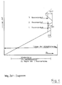
Fig. 6 zeigt schließlich in einer graphischen Darstellung die Abhängigkeit des Wärmeübergangskoeffizienten α für das obere Düsensystem und das untere Düsensystem in Abhängigkeit von der Geschwindigkeit v der durchlaufenden Glasscheiben 7. In beiden Fällen also oben und, beträgt der geometrisch freie Düsenflächenanteil 3,4 %.6 finally shows a graphical representation of the dependence of the heat transfer coefficient α for the upper nozzle system and the lower nozzle system as a function of the speed v of the glass panes 7 passing through. In both cases, therefore, at the top and, the geometrically free portion of the nozzle area is 3.4%.
Es läßt sich erkennen, daß die Meßpunkte für den Wärmeübergangskoeffizienten α beim oberen und beim unteren Düsensystem praktisch identisch sind, d. h. an der Ober- und Unterseite der Glasscheibe gibt es keinen meßbaren Unterschied. Ein solcher Verlauf läßt sich mit den bisher üblichen Techniken nur mit extremem Aufwand realisieren.It can be seen that the measuring points for the heat transfer coefficient α are practically identical in the upper and in the lower nozzle system, i. H. there is no measurable difference on the top and bottom of the glass pane. Such a course can only be implemented with extreme effort using the techniques which have been customary to date.
Claims (23)
- A high-convection gas jet section for roller-guided sheet-like material, more particularly for tempering thin flat glass sheets, comprisinga) a lower nozzle array (2) having nozzle ribs (2a) arranged centrally and parallelly between the rollers (1) and provided with nozzle orifices, andb) an upper nozzle array (3), the nozzle ribs (3b) of which being provided with nozzle orifices and arranged symmetrically to the vertical axis of an associated, opposite lower nozzle rib (2a),c) the gas jets from some nozzle orifices impinging perpendicularly on the surface of said material and the gas jets from other nozzle orifices impinging obliquely on said surface,characterized by the following features:d) the nozzle trays (4) of said upper nozzle ribs (3a) have the cross section of a letter "M" extended by a center strip (4a);e) the width of said nozzle tray (4) of said upper nozzle ribs (3b) is greater than the horizontal distance between said rollers (1) and smaller than the roller pitch (T);f) the center strip (4a) and the two upswept inner legs (4b₁, 4b₂) of said nozzle tray (4) of said upper nozzle ribs (3b) are provided with nozzle orifices (4d, 4e, 4f), andg) the smallest distance (5) of said upper nozzle ribs (3b) from the upper side of said material (7) is greater than the smallest distance (6) of said lower nozzle ribs (2a) from the underside of said material (7).
- The high-convection gas jet section as set forth in claim 1, characterized by the following dimensional ranges for said nozzle trays (4) of said upper nozzle ribs (3b):- for a total width BU of said lower nozzle ribs (2a) the width BP of the substantially planar middle strip (4a) is in the following range:
 - the upsweep angle of the two inner legs (4b₁, 4b₂) of said nozzle tray (4) is in the range from 5° to 10°;- with respect to the total width BU of said lower nozzle ribs (82a) the width BK of said two inner upswept legs (4b₁, 4b₂) of said upper nozzle tray (4) is in the following range:
 - the inclination of the two downswept outer legs (4c) of said upper nozzle trays (4) to the horizontal is in the range of 40° to 50°, more particularly roughly 45°; and- with respect to the total width BU of said lower ribs of nozzles (2a) the width BR of said two downswept outer legs (4c) of said upper nozzle trays (4) is in the following range:
- The high-convection gas jet section as set forth in claim 1 or claim 2, characterized in that the plane middle strip (4a) of said upper nozzle trays (4) has an odd number of rows of nozzle orifices (4f) with a relatively small center-spacing or hole pitch and a relatively small diameter, that the rows of said nozzle orifices (4f) are spaced away from each other by roughly a single center-spacing or hole pitch and, in the longitudinal direction, are mutually offset by half a center-spacing or hole pitch in each case, that said upswept inner legs (4b₁, 4b₂) of said upper nozzle trays (4) feature further rows of nozzle orifices (4d, 4e) having a greater orifice diameter and a greater center-spacing or hole pitch, and that the diameters and/or the center-spacing or hole pitch of said nozzle orifices (4d, 4e, 4f) increase with the ordinal number of rows of said nozzle orifices (4d, 4e, 4f) from the inside to the outside.
- The high-convection gas jet section as set forth in any of the claims 1 to 3, characterized in that the nozzle trays (4) of said upper nozzle ribs (3b) feature three rows of nozzle orifices (4f) in the center strip (4a) and the two adjoining upwardly inclined legs (4b₁,4b₂) each have two rows of nozzle orifices (4d, 4e) on twice the center-spacing or hole pitch.
- The high-convection gas jet section as set forth in any of the claims 1 to 4, characterized in that said nozzle orifices in said upper and lower nozzle ribs (2a, 3b) generate by selection of their position, their diameters and their angles of inclination of their nozzle jets an impingement pattern on one side of the material which is mirror-inverse to that on the other side of the material.
- The high-convection gas jet section as set forth in any of the claims 1 to 5, characterized in that the geometric nozzle exit area relative to the jetted area on one side of said material (7) is roughly 2% to roughly 5%, and that the nozzle exit area for the upper and lower nozzle ribs (2a, 3b) is equal.
- The high-convection gas jet section as set forth in any of the claims 1 to 6, characterized in that the percentage area of the nozzle orifices decreases in the conveying direction of the jet section.
- The high-convection gas jet section as set forth in any of the claims 1 to 7, characterized in that the pitch of said rollers (1) and of said nozzle ribs (2a, 3b) lies in the range of roughly 60 mm to roughly 150 mm.
- The high-convection gas jet section as set forth in any of the claims 1 to 8, characterized in that said lower nozzle ribs (2a) are inclined in cross section in the manner of a hipped roof, and that both the two inclined edge regions (2a₂) and the horizontal region (2a₁) feature nozzle orifices (2b, 2c, 2d).
- The high-convection gas jet section as set forth in any of the claims 1 to 9, characterized in that the distance (5) of said upper nozzle array (3) from the surface of the roller group and the distance (6) of said lower nozzle array (2) from the surface of said roller group are adjustable.
- The high-convection gas jet section as set forth in any of the claims 1 to 10, characterized in that the distance (5) of said upper nozzle array (3) from the material (7) is roughly twice that of distance (6) of said lower nozzle array (2) from the material (7).
- The high-convection gas jet section as set forth in any of the claims 1 to 11, characterized in that the jetting pressures for said upper nozzle array (3) and for said lower nozzle array (2) are approximately equal.
- The high-convection gas jet section as set forth in any of the claims 1 to 12, characterized in that when said jet section is employed for tempering glass sheets (7) the jetting pressure is reduced on or following entry of the glass sheets.
- The high-convection gas jet section as set forth in claim 13, characterized in that said jetting pressure is reduced by reducing the speed of rotation of the fans supplying said nozzle arrays (2, 3).
- The high-convection gas jet section as set forth in any of the claims 1 to 14, characterized in that the gas pressure diminishes in both said upper nozzle ribs (3b) and said lower nozzle ribs (2b) from nozzle rib to nozzle rib in the conveyance direction of the sheet-like material.
- The high-convection gas jet section as set forth in claim 15, characterized in that the flow at the inlet in the nozzle ribs (2a, 3b) is individually throttled.
- The high-convection gas jet section as set forth in any of the claims 1 to 16, characterized in that when said jet section is employed for tempering glass sheets (7) each sheet (7) is halted following entry in the cooling section and subsequently reversed at least once by a stroke which is a multiple of half the roller pitch (T).
- The high-convection gas jet section as set forth in claim 17, characterized in that said reversing stroke differs for at least one reversal.
- The high-convection gas jet section as set forth in any of the claims 1 to 18 for tempering thin sheets of glass, characterized in that the upper nozzle ribs (3b) as a whole are pivotally mounted about a pivot axis (10) on a frame (11) which is vertically adjustable by means of lifting spindles (12) and a lifting spindle drive (13), that the entire upper nozzle array (3) is pivotable upwards about said pivot axis (10) by means of a pneumatic cylinder (14), and that said lower nozzle array (2) is pivotable about an height-adjustable pivot axis (15) by means of a pneumatic cylinder (17) and is pressable against a height-adjustable stop (16) by means of said cylinder (17).
- The high-convection gas jet section as set forth in claim 19, characterized in that displacement pickups are provided for sensing the height displacement, and that said height displacement is motor-powered via a computer-aided feedback control system.
- The high-convection gas jet section as set forth in any of the claims 1 to 20 for tempering sheets of glass, characterized in that said rollers (1) for guiding said glass sheets (7) are provided fully circumferentially with supports for said glass sheets (7), these supports taking up merely a minor part of the respective roller surface area.
- The high-convection gas jet section as set forth in claim 21, characterized in that said supports are formed by O-rings of a fluorene caoutchouc.
- The high-convection gas jet section as set forth in claim 21, characterized in that said supports consist of silicate fibrous material, especially calcium silicate fibrous material, in conjunction with suitable binders.
Applications Claiming Priority (2)
| Application Number | Priority Date | Filing Date | Title |
|---|---|---|---|
| DE4002546A DE4002546C2 (en) | 1990-01-29 | 1990-01-29 | High-convection gas jet nozzle section for flat material guided over rollers, and method for their operation |
| DE4002546 | 1990-01-29 |
Publications (3)
| Publication Number | Publication Date |
|---|---|
| EP0440113A2 EP0440113A2 (en) | 1991-08-07 |
| EP0440113A3 EP0440113A3 (en) | 1992-07-15 |
| EP0440113B1 true EP0440113B1 (en) | 1995-09-27 |
Family
ID=6398985
Family Applications (1)
| Application Number | Title | Priority Date | Filing Date |
|---|---|---|---|
| EP91100999A Expired - Lifetime EP0440113B1 (en) | 1990-01-29 | 1991-01-25 | Jet road of high convection gas for plate-like materials transported by rolls |
Country Status (5)
| Country | Link |
|---|---|
| US (1) | US5094678A (en) |
| EP (1) | EP0440113B1 (en) |
| AT (1) | ATE128442T1 (en) |
| DE (2) | DE4002546C2 (en) |
| ES (1) | ES2078359T3 (en) |
Families Citing this family (30)
| Publication number | Priority date | Publication date | Assignee | Title |
|---|---|---|---|---|
| ATE120724T1 (en) * | 1990-01-26 | 1995-04-15 | Glasstech Inc | DEVICE FOR HARDENING GLASS PANELS CONVEYED ON ROLLERS. |
| FI91248C (en) * | 1992-09-23 | 1994-06-10 | Aulis Bertin | Glass heat treatment method |
| DE4402606C2 (en) * | 1994-01-28 | 1996-09-05 | Kramer Carl | High-convection gas jet nozzle section for the thermal prestressing of flat goods, in particular glass panes |
| US5669954A (en) * | 1994-06-20 | 1997-09-23 | Gas Research Institute | Forced convection heating apparatus and process for heating glass sheets therewithin |
| US5672191A (en) * | 1994-06-20 | 1997-09-30 | Gas Research Institute | Forced convection heating apparatus and process for heating glass sheets therewithin |
| US5746799A (en) * | 1994-06-20 | 1998-05-05 | Gas Research Institute | Process for heating glass sheets within a forced convection heating apparatus by mixing and distributing spent working fluid and combustion gases |
| DE19544995C1 (en) * | 1995-12-02 | 1997-04-03 | Kramer Carl | Horizontal toughening line for flat glass |
| US6045358A (en) * | 1996-01-19 | 2000-04-04 | Glasstech, Inc. | Forced convection heating apparatus and process for heating glass sheets therewithin |
| DE29603022U1 (en) * | 1996-02-21 | 1996-04-18 | Ipsen Ind Int Gmbh | Device for quenching metallic workpieces |
| EP1124765B1 (en) * | 1998-10-21 | 2013-04-03 | Glasstech, Inc. | Uniform distribution quenching of formed glass sheets |
| US6050814A (en) * | 1998-12-09 | 2000-04-18 | Glasstech, Inc. | Forced convection furnace for heating glass sheets |
| US7387236B2 (en) * | 2001-10-09 | 2008-06-17 | Delaware Capital Formation, Inc. | Dispensing of currency |
| US20050098622A1 (en) * | 2001-10-09 | 2005-05-12 | Gregory Jantsch | Dispensing of currency |
| ITMI20021506A1 (en) * | 2002-07-10 | 2004-01-12 | Danieli Off Mecc | BELT TEMPERATURE ADJUSTMENT DEVICE IN A METAL BELT CONTINUOUS CASTING SYSTEM |
| DE602004027235D1 (en) * | 2003-03-31 | 2010-07-01 | Glassrobots Oy | REFRIGERATED HEATING OVEN FOR A PREFABLICATED GLASS WASHER |
| US20060150683A1 (en) * | 2005-01-11 | 2006-07-13 | Glasstech, Inc. | Apparatus and method for glass sheet quenching |
| US20070001383A1 (en) * | 2005-06-20 | 2007-01-04 | Gregory Jantsch | Dispensing of currency |
| US20090173106A1 (en) * | 2008-01-04 | 2009-07-09 | Boisselle Robert J | Glass tempering method and apparatus |
| FI124601B (en) * | 2010-09-22 | 2014-10-31 | Glaston Services Ltd Oy | Munstyckskroppskonstruktion |
| CN102757173B (en) * | 2012-06-22 | 2014-11-12 | 杭州精工机械有限公司 | Ultrathin toughened glass production line and production method |
| BE1024010B1 (en) * | 2012-09-21 | 2017-10-27 | Agc Glass Europe | BOMBAGE OF GLAZING |
| US9624120B2 (en) * | 2013-01-18 | 2017-04-18 | Feracitas Oy | Method for improving an air circulation and a way for heating air in a glass tempering oven |
| US9423177B2 (en) * | 2013-02-22 | 2016-08-23 | Ricoh Company, Ltd. | Force-balancing gas flow in dryers for printing systems |
| US9573833B2 (en) * | 2014-03-31 | 2017-02-21 | Corning Incorporated | Method and lift jet floatation system for shaping thin glass |
| CN103951176B (en) * | 2014-04-11 | 2016-06-15 | 洛阳兰迪玻璃机器股份有限公司 | The process furnace of a kind of rapid heating sheet glass |
| DE202016006191U1 (en) | 2016-09-28 | 2018-01-02 | FASA GmbH Gesellschaft für Management, Innovation und Consulting | Schwibbogen in the style of the Erzgebirge arts and crafts |
| CN107661829A (en) * | 2017-09-30 | 2018-02-06 | 江苏云端重工科技有限公司 | A kind of bitumen recovery Special cleaning shower nozzle |
| DE202017006469U1 (en) | 2017-12-16 | 2018-03-15 | Thomas Achatz | Schwibbogen in the style of the Erzgebirge folk art |
| US20220169552A1 (en) * | 2020-12-01 | 2022-06-02 | Tung Chang Machinery And Engineering Co., Ltd. | Wind outlet structure and cooling device |
| DE202021002276U1 (en) | 2021-06-21 | 2021-07-12 | Kleinkunst aus dem Erzgebirge Müller GmbH | Lichterspitze in the style of the Erzgebirge folk art |
Family Cites Families (16)
| Publication number | Priority date | Publication date | Assignee | Title |
|---|---|---|---|---|
| US3353946A (en) * | 1964-01-29 | 1967-11-21 | Permaglass | Blasthead structure for tempering glass sheets |
| US3404974A (en) * | 1965-04-21 | 1968-10-08 | Corning Glass Works | Cooling arrangement for glass forming equipment |
| US3595636A (en) * | 1968-05-03 | 1971-07-27 | Ppg Industries Inc | Apparatus for shaping and cooling glass sheets |
| DE2256087C3 (en) * | 1972-11-16 | 1982-06-24 | Vits-Maschinenbau Gmbh, 4018 Langenfeld | Device for drying a web of material lying on an essentially flat support |
| US3875766A (en) * | 1973-12-20 | 1975-04-08 | Fifth Res | Method for the direct manufacture of discrete tempered glass sheets |
| AT359229B (en) * | 1975-03-07 | 1980-10-27 | Siemens Ag Oesterreich | TRANSPORT DEVICE FOR GLASS PANELS HEATED TO SOFTENING TEMPERATURE |
| IE47093B1 (en) * | 1977-06-23 | 1983-12-14 | Triplex Safety Glass Co | Improvements in or relating to toughened glass sheets and method for their production |
| DE2827757A1 (en) * | 1978-06-24 | 1980-01-10 | Johannes Heyen | Tunnel sealing lining web - is self-adhesively coated on both sides and covered with strippable silicone paper backing |
| GB2064507B (en) * | 1979-11-21 | 1983-06-02 | Bfg Glassgroup | Removing broken fragments formed during glass treatment eg tempering |
| US4323385A (en) * | 1980-07-21 | 1982-04-06 | Ppg Industries, Inc. | Nozzle arrangement for glass sheet tempering apparatus |
| US4363163A (en) * | 1980-11-13 | 1982-12-14 | Mcmaster Harold | Quench roll including helically wrapped support |
| EP0114168B1 (en) * | 1983-01-21 | 1987-07-29 | Karl-Heinz Dipl.-Ing. Dicks | Apparatus for bending glass sheets |
| DE3150859C1 (en) * | 1981-12-22 | 1983-03-10 | Karl-Heinz Dipl.-Ing. 5107 Lammersdorf Dicks | Apparatus for curving panes of glass |
| FR2547575B1 (en) * | 1983-06-14 | 1985-10-04 | Saint Gobain Vitrage | GLASS TEMPERING IMPROVEMENT |
| FI76315C (en) * | 1986-10-29 | 1988-10-10 | Kyro Oy | Apparatus in the cooling compartment for a glass curing plant |
| FI76314C (en) * | 1986-10-29 | 1988-10-10 | Kyro Oy | STROEMNINGSHINDER I KYLAVDELNINGEN TILL EN GLASHAERDNINGSANLAEGGNING. |
-
1990
- 1990-01-29 DE DE4002546A patent/DE4002546C2/en not_active Expired - Lifetime
-
1991
- 1991-01-25 AT AT91100999T patent/ATE128442T1/en not_active IP Right Cessation
- 1991-01-25 DE DE59106563T patent/DE59106563D1/en not_active Expired - Fee Related
- 1991-01-25 EP EP91100999A patent/EP0440113B1/en not_active Expired - Lifetime
- 1991-01-25 ES ES91100999T patent/ES2078359T3/en not_active Expired - Lifetime
- 1991-01-28 US US07/646,035 patent/US5094678A/en not_active Expired - Lifetime
Also Published As
| Publication number | Publication date |
|---|---|
| DE4002546A1 (en) | 1991-08-01 |
| ES2078359T3 (en) | 1995-12-16 |
| US5094678A (en) | 1992-03-10 |
| ATE128442T1 (en) | 1995-10-15 |
| EP0440113A3 (en) | 1992-07-15 |
| EP0440113A2 (en) | 1991-08-07 |
| DE4002546C2 (en) | 1994-07-14 |
| DE59106563D1 (en) | 1995-11-02 |
Similar Documents
| Publication | Publication Date | Title |
|---|---|---|
| EP0440113B1 (en) | Jet road of high convection gas for plate-like materials transported by rolls | |
| DE4336364C2 (en) | Device for heating or cooling tabular or band-shaped items to be treated made of glass or ceramic material | |
| EP0541630B1 (en) | Device for cooling extruded profiles | |
| DE69833871T2 (en) | DEVICE FOR CURING CURVED GLASS PANES | |
| DE3612720C2 (en) | ||
| DE1811435A1 (en) | Method and device for toughening glass panes | |
| DE19649073C2 (en) | Device for cooling extruded profiles | |
| EP0114168B1 (en) | Apparatus for bending glass sheets | |
| AT406046B (en) | DEVICE FOR TRANSPORTING AND COOLING GLASS PANES | |
| EP3655367A1 (en) | Blower box for thermal prestressing of glass panes | |
| DE2163268B2 (en) | OVEN FOR HEATING GLASS PANELS | |
| EP3583078A1 (en) | Tempering frame for tempering glass panes | |
| WO2018015108A1 (en) | Nozzle strip for a blowing box for thermally prestressing glass panes | |
| DE2840834C3 (en) | Device for pretensioning the upper of the two simultaneously bent individual panes of a composite safety pane in the bending furnace | |
| DE2118589A1 (en) | Method and device for the continuous deflection of a glass ribbon in a plastic state | |
| EP0425998B1 (en) | Blow-back barrier | |
| DE3150859C1 (en) | Apparatus for curving panes of glass | |
| DE4402606C2 (en) | High-convection gas jet nozzle section for the thermal prestressing of flat goods, in particular glass panes | |
| DE2462154C3 (en) | Device for thermal toughening of glass panes | |
| DE1596632B1 (en) | Method and device for hardening sheet glass | |
| DE19642876C1 (en) | Glass pane bending assembly | |
| DE1596632C (en) | Method and device for hardening sheet glass | |
| DE2447411B2 (en) | Device for toughening large panes of glass | |
| DE202021004035U1 (en) | Blow box for thermal toughening of glass panes | |
| DE102018123284A1 (en) | Device for tempering glass panes |
Legal Events
| Date | Code | Title | Description |
|---|---|---|---|
| PUAI | Public reference made under article 153(3) epc to a published international application that has entered the european phase |
Free format text: ORIGINAL CODE: 0009012 |
|
| AK | Designated contracting states |
Kind code of ref document: A2 Designated state(s): AT BE CH DE ES FR GB IT LI NL |
|
| PUAL | Search report despatched |
Free format text: ORIGINAL CODE: 0009013 |
|
| AK | Designated contracting states |
Kind code of ref document: A3 Designated state(s): AT BE CH DE ES FR GB IT LI NL |
|
| 17P | Request for examination filed |
Effective date: 19921229 |
|
| 17Q | First examination report despatched |
Effective date: 19941017 |
|
| GRAA | (expected) grant |
Free format text: ORIGINAL CODE: 0009210 |
|
| ITF | It: translation for a ep patent filed |
Owner name: BARZANO' E ZANARDO MILANO S.P.A. |
|
| AK | Designated contracting states |
Kind code of ref document: B1 Designated state(s): AT BE CH DE ES FR GB IT LI NL |
|
| REF | Corresponds to: |
Ref document number: 128442 Country of ref document: AT Date of ref document: 19951015 Kind code of ref document: T |
|
| GBT | Gb: translation of ep patent filed (gb section 77(6)(a)/1977) |
Effective date: 19950928 |
|
| REF | Corresponds to: |
Ref document number: 59106563 Country of ref document: DE Date of ref document: 19951102 |
|
| REG | Reference to a national code |
Ref country code: ES Ref legal event code: FG2A Ref document number: 2078359 Country of ref document: ES Kind code of ref document: T3 |
|
| ET | Fr: translation filed | ||
| PLBE | No opposition filed within time limit |
Free format text: ORIGINAL CODE: 0009261 |
|
| STAA | Information on the status of an ep patent application or granted ep patent |
Free format text: STATUS: NO OPPOSITION FILED WITHIN TIME LIMIT |
|
| 26N | No opposition filed | ||
| REG | Reference to a national code |
Ref country code: GB Ref legal event code: IF02 |
|
| PGFP | Annual fee paid to national office [announced via postgrant information from national office to epo] |
Ref country code: DE Payment date: 20050119 Year of fee payment: 15 |
|
| PGFP | Annual fee paid to national office [announced via postgrant information from national office to epo] |
Ref country code: GB Payment date: 20050120 Year of fee payment: 15 |
|
| PGFP | Annual fee paid to national office [announced via postgrant information from national office to epo] |
Ref country code: NL Payment date: 20050121 Year of fee payment: 15 Ref country code: CH Payment date: 20050121 Year of fee payment: 15 Ref country code: AT Payment date: 20050121 Year of fee payment: 15 |
|
| PGFP | Annual fee paid to national office [announced via postgrant information from national office to epo] |
Ref country code: FR Payment date: 20050124 Year of fee payment: 15 |
|
| PGFP | Annual fee paid to national office [announced via postgrant information from national office to epo] |
Ref country code: ES Payment date: 20050128 Year of fee payment: 15 |
|
| PGFP | Annual fee paid to national office [announced via postgrant information from national office to epo] |
Ref country code: BE Payment date: 20050302 Year of fee payment: 15 |
|
| PG25 | Lapsed in a contracting state [announced via postgrant information from national office to epo] |
Ref country code: GB Free format text: LAPSE BECAUSE OF NON-PAYMENT OF DUE FEES Effective date: 20060125 Ref country code: AT Free format text: LAPSE BECAUSE OF NON-PAYMENT OF DUE FEES Effective date: 20060125 |
|
| PG25 | Lapsed in a contracting state [announced via postgrant information from national office to epo] |
Ref country code: ES Free format text: LAPSE BECAUSE OF NON-PAYMENT OF DUE FEES Effective date: 20060126 |
|
| PG25 | Lapsed in a contracting state [announced via postgrant information from national office to epo] |
Ref country code: LI Free format text: LAPSE BECAUSE OF NON-PAYMENT OF DUE FEES Effective date: 20060131 Ref country code: FR Free format text: LAPSE BECAUSE OF NON-PAYMENT OF DUE FEES Effective date: 20060131 Ref country code: CH Free format text: LAPSE BECAUSE OF NON-PAYMENT OF DUE FEES Effective date: 20060131 Ref country code: BE Free format text: LAPSE BECAUSE OF NON-PAYMENT OF DUE FEES Effective date: 20060131 |
|
| PGFP | Annual fee paid to national office [announced via postgrant information from national office to epo] |
Ref country code: IT Payment date: 20060131 Year of fee payment: 16 |
|
| PG25 | Lapsed in a contracting state [announced via postgrant information from national office to epo] |
Ref country code: NL Free format text: LAPSE BECAUSE OF NON-PAYMENT OF DUE FEES Effective date: 20060801 Ref country code: DE Free format text: LAPSE BECAUSE OF NON-PAYMENT OF DUE FEES Effective date: 20060801 |
|
| REG | Reference to a national code |
Ref country code: CH Ref legal event code: PL |
|
| GBPC | Gb: european patent ceased through non-payment of renewal fee |
Effective date: 20060125 |
|
| NLV4 | Nl: lapsed or anulled due to non-payment of the annual fee |
Effective date: 20060801 |
|
| REG | Reference to a national code |
Ref country code: FR Ref legal event code: ST Effective date: 20060929 |
|
| REG | Reference to a national code |
Ref country code: ES Ref legal event code: FD2A Effective date: 20060126 |
|
| BERE | Be: lapsed |
Owner name: INGENIEURGESELLSCHAFT FUR WARMETECHNIK STROMUNGSTE Effective date: 20060131 |
|
| PG25 | Lapsed in a contracting state [announced via postgrant information from national office to epo] |
Ref country code: IT Free format text: LAPSE BECAUSE OF NON-PAYMENT OF DUE FEES Effective date: 20070125 |