EP0439735B1 - Dichtesensor mit offenem Gehäuse - Google Patents
Dichtesensor mit offenem Gehäuse Download PDFInfo
- Publication number
- EP0439735B1 EP0439735B1 EP90123447A EP90123447A EP0439735B1 EP 0439735 B1 EP0439735 B1 EP 0439735B1 EP 90123447 A EP90123447 A EP 90123447A EP 90123447 A EP90123447 A EP 90123447A EP 0439735 B1 EP0439735 B1 EP 0439735B1
- Authority
- EP
- European Patent Office
- Prior art keywords
- elongated
- conductor
- outer conductors
- density
- electrode
- Prior art date
- Legal status (The legal status is an assumption and is not a legal conclusion. Google has not performed a legal analysis and makes no representation as to the accuracy of the status listed.)
- Expired - Lifetime
Links
- 239000004020 conductor Substances 0.000 claims abstract description 69
- 238000007654 immersion Methods 0.000 claims abstract description 27
- 230000001419 dependent effect Effects 0.000 claims abstract description 4
- 239000003990 capacitor Substances 0.000 claims description 22
- 229910001218 Gallium arsenide Inorganic materials 0.000 claims description 2
- 230000005669 field effect Effects 0.000 claims description 2
- 229910052751 metal Inorganic materials 0.000 claims description 2
- 239000002184 metal Substances 0.000 claims description 2
- JBRZTFJDHDCESZ-UHFFFAOYSA-N AsGa Chemical compound [As]#[Ga] JBRZTFJDHDCESZ-UHFFFAOYSA-N 0.000 claims 1
- 239000012530 fluid Substances 0.000 abstract description 28
- 230000035939 shock Effects 0.000 abstract description 3
- 239000007788 liquid Substances 0.000 description 12
- 239000000463 material Substances 0.000 description 10
- 239000000523 sample Substances 0.000 description 10
- 238000005259 measurement Methods 0.000 description 7
- 239000007789 gas Substances 0.000 description 5
- 239000001257 hydrogen Substances 0.000 description 5
- 229910052739 hydrogen Inorganic materials 0.000 description 5
- UFHFLCQGNIYNRP-UHFFFAOYSA-N Hydrogen Chemical compound [H][H] UFHFLCQGNIYNRP-UHFFFAOYSA-N 0.000 description 4
- 238000000034 method Methods 0.000 description 4
- 235000019198 oils Nutrition 0.000 description 4
- 230000010355 oscillation Effects 0.000 description 4
- 239000007787 solid Substances 0.000 description 4
- 239000000446 fuel Substances 0.000 description 3
- 239000000203 mixture Substances 0.000 description 3
- 239000012811 non-conductive material Substances 0.000 description 3
- 239000000356 contaminant Substances 0.000 description 2
- 230000001595 contractor effect Effects 0.000 description 2
- 238000001739 density measurement Methods 0.000 description 2
- 238000010586 diagram Methods 0.000 description 2
- 238000006073 displacement reaction Methods 0.000 description 2
- 230000000694 effects Effects 0.000 description 2
- 239000004065 semiconductor Substances 0.000 description 2
- XLYOFNOQVPJJNP-UHFFFAOYSA-N water Substances O XLYOFNOQVPJJNP-UHFFFAOYSA-N 0.000 description 2
- RYGMFSIKBFXOCR-UHFFFAOYSA-N Copper Chemical compound [Cu] RYGMFSIKBFXOCR-UHFFFAOYSA-N 0.000 description 1
- 239000004677 Nylon Substances 0.000 description 1
- 239000004743 Polypropylene Substances 0.000 description 1
- 229910052782 aluminium Inorganic materials 0.000 description 1
- XAGFODPZIPBFFR-UHFFFAOYSA-N aluminium Chemical compound [Al] XAGFODPZIPBFFR-UHFFFAOYSA-N 0.000 description 1
- 238000005219 brazing Methods 0.000 description 1
- 230000003139 buffering effect Effects 0.000 description 1
- 238000006243 chemical reaction Methods 0.000 description 1
- 238000002485 combustion reaction Methods 0.000 description 1
- 229910052802 copper Inorganic materials 0.000 description 1
- 239000010949 copper Substances 0.000 description 1
- 235000012343 cottonseed oil Nutrition 0.000 description 1
- 238000001514 detection method Methods 0.000 description 1
- 230000007613 environmental effect Effects 0.000 description 1
- 239000002360 explosive Substances 0.000 description 1
- 150000002431 hydrogen Chemical class 0.000 description 1
- 239000011810 insulating material Substances 0.000 description 1
- 230000002452 interceptive effect Effects 0.000 description 1
- 239000003949 liquefied natural gas Substances 0.000 description 1
- 229920001778 nylon Polymers 0.000 description 1
- 239000011368 organic material Substances 0.000 description 1
- -1 polypropylene Polymers 0.000 description 1
- 229920001155 polypropylene Polymers 0.000 description 1
- 230000001681 protective effect Effects 0.000 description 1
- 238000000926 separation method Methods 0.000 description 1
- 238000005476 soldering Methods 0.000 description 1
- 229910001220 stainless steel Inorganic materials 0.000 description 1
- 239000010935 stainless steel Substances 0.000 description 1
- 238000003466 welding Methods 0.000 description 1
Images

Classifications
-
- G—PHYSICS
- G01—MEASURING; TESTING
- G01N—INVESTIGATING OR ANALYSING MATERIALS BY DETERMINING THEIR CHEMICAL OR PHYSICAL PROPERTIES
- G01N27/00—Investigating or analysing materials by the use of electric, electrochemical, or magnetic means
- G01N27/02—Investigating or analysing materials by the use of electric, electrochemical, or magnetic means by investigating impedance
- G01N27/22—Investigating or analysing materials by the use of electric, electrochemical, or magnetic means by investigating impedance by investigating capacitance
- G01N27/226—Construction of measuring vessels; Electrodes therefor
-
- G—PHYSICS
- G01—MEASURING; TESTING
- G01N—INVESTIGATING OR ANALYSING MATERIALS BY DETERMINING THEIR CHEMICAL OR PHYSICAL PROPERTIES
- G01N9/00—Investigating density or specific gravity of materials; Analysing materials by determining density or specific gravity
Definitions
- This invention relates to a system for determining the density of cryogenic liquids, solids, gases and mixtures and, more particularly, relates to an immersion cell for use in such systems.
- cryogens such as liquified gases and associated solids, gases and mixtures thereof.
- U.S. Patent No. 3,933,030 discloses a system of taking continuous simultaneous, or sequential, readings of density in a cryogenic tank to monitor density changes and thereby create a density profile of the content of the tank to avoid the occurrence of rollover, or density inversions which, when left unchecked, can create a sudden emission of large quantities of highly flammable and explosive gases.
- U.S. Patent No. 3,933,030 suggests that the density of cryogenic liquids can be continuously determined electrically by the use of differential capacitance measurements.
- Density is determined from the Clausious-Mosotti equation by determining the dielectric constant of the cryogenic liquid with a dielectric cell of known capacitance, measuring the temperature of the cryogenic liquid and calculating the density of the cryogenic liquid from the Clausious-Mosotti equation.
- U.S. Patent No. 4,555,661 discloses method and apparatus for determining a dielectric constant of fluid materials through a differential capacitance technique.
- the disclosed apparatus of U.S. Patent No. 4,555,661 consists of a three electrode device which may be placed in a container of fluid material.
- the electrodes of the device may be three planar electrodes or three coaxial cylindrical electrodes.
- the two remote electrodes are connected across the terminals of a free-running oscillator and determine its frequency of oscillation by their area and their separation and the dielectric constant of the material between the electrodes.
- the intermediate electrode is connected to a switch which alternatively connects the intermediate electrode to one of the remote electrodes and disconnects the intermediate electrode from the circuit thereby changing the frequency of oscillation. Dielectric constant is determined from the frequency difference.
- U.S. Patent No. 3,903,478 discloses a fluid density measuring device including fluid capacitance test cell comprising three coaxial conductive cylindrical electrodes surrounded by a protective outer tube.
- the test cell capacitor is formed by inner and outer concentric cylinders, which are interconnected, and the intermediate concentric cylinder and is connected with a 16 kHz precision oscillator to provide a current through the test cell capacitor that is proportional to the density of the fluid passing through the test cell.
- the 16 kHz precision oscillator also provides a current through another capacitor which is 180° out-of-phase, and both currents are directed to an amplifier which provides an output proportional to the difference in the currents and therefore the density of the fluid through the test cell.
- U.S. Patent No. 4,544,880 discloses a microwave probe for measuring the amount of contaminants or water in crankcase oil, comprising a coaxial cable having a tip including five substantially parallel wires shorted together at one end and connected at the other end to the coaxial cable.
- the microwave probe includes a central wire connected to the center wire of the coaxial cable and four outer wires connected to the sheath of the coaxial cable at one end and connected to each other and to the center wire at the other end.
- the size and geometry of the wires is selected so that the impedance of the tip, when immersed in oil, substantially matches the impedance of the coaxial cable.
- the dielectric constant of the oil and the contaminant content of the oil is measured by connecting the microwave probe to a microwave oscillator and measuring either the voltage level of the standing wave at a fixed position along the interconnecting coaxial cable, or the null location of the standing wave along the interconnecting coaxial cable, or the operating frequency of the microwave oscillator required to keep the standing wave in a fixed position along the interconnecting coaxial cable.
- U.S. Patent No. 3,375,716 discloses a multivibrator driven with a fluid cell capacitor as a sensor element in the timing circuit of the multivibrator, to provide a liquid level gauge by varying the frequency of the multivibrator as a result of variations in capacitance of the sensor as liquid fills the fluid cell capacitor.
- U.S. Patent No. 3,739,266 discloses a system for protecting the moisture content of material such as cottonseed by the variation in the dielectric constant of a flow of such material past capacitor plates.
- the capacitor plates of U.S. Patent No. 3,739,266 are connected to an oscillator generating an electrical signal whose frequency is proportional to the dielectric constant of the material.
- U.S. Patent No. 4,011,746 discloses a liquid density measurement system comprising a capacitance probe and a temperature sensor both immersible in a liquid whose density is to be measured.
- This system is particularly suited to measuring the density of liquid mixtures such as liquid natural gas, which is a non-polar organic material that follows the Clausious-Mosotti equation establishing the relationship between dielectric constant and density.
- the signals derived from the compacitance probe and temperature sensor are scaled and used to calculate density pursuant to the Clausious-Mosotti equation.
- U.S. Patent No. 4,417,472 discloses a liquid level sensor comprising four elongated L-shaped conductive capacitor elements arranged in a cruciform configuration.
- the four L-shaped conductive elements are sandwiched with a material of known dielectric constant to comprise one solid cross of the cruciform and to provide two open capacitor-forming spaces in the other cross of the cruciform that receive varying levels of fluid, thereby forming two capacitors of variable capacitance depending upon the level of the fluid in the spaces.
- U.S. Patent No. 4,429,272 discloses an apparatus for detecting the presence of water in fuel for an internal combustion engine by the change in dielectric constant of the fuel detected by two electrodes immersed in the fuel.
- U.S. Patent No. 4,468,611 discloses a four cavity fluid cell for use in a Wheatstone bridge configuration to equalize the effects of fluid characteristics, pressure and temperature in the measurement of the dielectric constant of a sampled fluid.
- U.S. Patent No. 4,468,611 discloses a plurality of configurations forming four fluid capacitance-determining cells for connection into the Wheatstone bridge, including four L-shaped elongated conductive capacitive elements arranged in a cruciform configuration and supported by a central dielectric member and a surrounding dielectric member to form four capacity cells in the arms of the cruciform.
- One of the opposing pairs of open cells is provided with reference fluid and the other opposing pair of fluid cells is provided with sample fluid whose dielectric constant is to be determined.
- U.S. Patent No. 4,673,869 discloses a circuit for matching of the capacitance of the sample and reference cells from outside the oven of a chromatographic analyzer system.
- the circuit includes a dielectric constant detector including a detection cell providing a sample cell formed by a pair of cylindrical electrodes spaced apart along a common axis and surrounded by a common electrode.
- a voltage applied to the varactor diode is manipulated until such time as the capacitance of the sample and reference cell are substantially matched.
- U.S. Patent No. 4,751,476 discloses a device and method for distinguishing between different fluids on the basis of their dielectric properties.
- the disclosed device includes two substantially parallel conductive surfaces that are positioned on opposite sides of a fluid conduit to form a substantially parallel plate capacitor.
- One of the conductive surfaces is connected through an inductor to a voltage source and the other of the conductive surfaces is connected to a resonator device.
- a transconductance amplifier is connected between the resonator device and the first conductive surface.
- the system provides oscillation when a known fluid passes between the parallel conductive plates but no oscillation when the fluid having different electrical dielectric properties passes between the plates because of the change of the capacitance due to differing dielectric constants.
- US-A-4,835,456 discloses an apparatus for measuring the density of cryogens, comprising a capacitor, between the electrodes of which the cryogenic may be disposed, an oscillator connected to said capacitor, said oscillator providing a varied frequency output dependent upon the capacitance of said capacitor and thus upon the density of the cryogen.
- This invention provides a light-weight density sensor having a rigid open structure that does not impede fluid flow and further provides the ability to accurately and reproducably measure dielectric constants and densities over long distances without interference from connecting coaxial cables during periods of vibration and thermal shock.
- the invention comprises a novel immersion cell and an oscillator circuit that provide a variable frequency output related to the dielectric constant of the cryogen within the immersion cell and from which the density of the cryogen can be determined.
- the immersion cell comprises an elongated conductor located centrally within a space formed by a plurality of outer elongated conductors spaced around the central conductor as defined in claim 1.
- the plurality of outer elongated conductors are electrically interconnected to form an open outer electrode.
- the open outer electrode does not impede the flow of cryogen into the immersion cell and by its structure permits accurate density determinations dependent upon the dielectric constant of cryogen present within the cell.
- the immersion cell is carried by a circuit housing for the oscillator formed of an electrically conductive material.
- the central electrode and the plurality of conductors forming the open outer electrode are carried at one end by the circuit housing.
- a wall of the circuit housing mechanically and electrically interconnects the plurality of outer conductors and further carries a dielectric support that carries the inner conductor and electrically isolates it from the plurality of outer conductors.
- the inner conductor and plurality of outer conductors are held at their other ends by a support of electrically non-conductive material to provide a rigid and economical structure.
- the oscillator circuit within the preferred environment is preferably the type commonly referred to as the Clapp LC Oscillator.
- the immersion cell sensor of this invention is open to slush cryogens and its inner conductor is electrically shielded by the open outer electrode formed by the plurality of the elongated conductors.
- the central electrode is a cylinder with a radius a
- the plurality of elongated outer conductors forming the open outer electrode comprise four cylindrical conductors equally spaced about the central cylindrical electrode on a circle having a radius b from the central axis of the central electrode, with their outer cylindrical surfaces having a radius b/4.
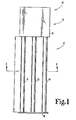
- Fig. 1 shows a density sensor 10 of the invention.
- the density sensor 10 comprises a first portion 11 and a second portion 12.
- the second portion 12 comprises an immersion cell comprising an inner electrode in the form of an elongated central conductor 13 and an outer electrode in the form of a plurality of elongated outer conductors 14.
- the elongated central conductor 13 and plurality of the elongated outer conductors 14 are carried at their one ends by a housing 15 of the first portion 11 and are supported at their distal ends by a support 16 of electrically non-conductive material.
- the housing 15 is formed from electrically conductive metal, such as copper, stainless steel, etc., to form a circuit compartment and to provide electromagnetic shielding for the circuit of the density sensor. As shown in Fig.
- the plurality of outer electrodes 14 are electrically and mechanically connected to the housing 15 to form the outer electrode.
- the electrical- mechanical connection of the outer conductor can be made by any convenient fastening method known in the art, such as by soldering, brazing, welding or by threaded fasteners and the like.
- the outer electrode of the immersion cell may be formed by integral extensions of housing 15.
- the inner elongated conductor 13, as shown in Fig. 2, is supported in spaced relationship from the walls of housing 15 by an electrically non-conductive support 17.
- the electrically isolating supports 16 and 17 may be any structurally sound, electrically non-conductive material such as nylon, polypropylene or any like reinforced insulating material.
- Elongated conductor 13 may thus be used as an electrode centrally located within an outer electrode 14 formed by the plurality of elongated conductors 14.
- the density sensor is thus a rigid, lightweight, one-piece structure adapted for convenient use over a wide temperature range from cryogenic temperatures to temperatures of 1000°F and higher.
- a preferable arrangement for the plurality of conductors 14 forming the outer electrode and the elongated conductor 13 forming the inner electrode is shown diagramatically in Fig. 3.
- the number of conductors 14 and their diameters are preferably chosen to provide effective shielding of the inner electrode.
- the outer electrodes are equally spaced about the inner electrode at a distance b, their outer diameters are preferably equal to b/n, where n equals the number of outer conductors 14.
- the outer electrode be comprised of four elongated tubular conductors, as shown in Figs. 1-3, equally spaced on a circle having a radius b from the central axis of the inner conductor 13, which is itself preferably an elongated tubular conductor.
- the inner conductor 13 of plurality of outer conductors 14 form a capacitor open to slush flow.
- the inner conductor 13 is electrically shielded by the plurality of outer conductors 14 forming the outer electrode so the capacitance between the inner electrode 13 and outer electrodes 14 is independent of the presence of nearby conductors and permits the immersion cell 12 to approach and be located close to the walls containing a fluid without interfering with the density measurement when the immersion cell is immersed in a cryogen or other fluid.
- the capacitance of the open cage capacitor formed by immersion cell 12 is insensitive to the displacement of the inner rod, and thermal contraction effects only the length of the cell L, which is predictable.
- a preferable circuit for use with the immersion cell 12 is a Clapp LC Oscillator 20.
- Fig. 4 is a circuit diagram of a preferred oscillator, which in this invention is preferably enclosed within the electronics compartment formed by the walls of housing 15.
- the immersion cell 12 forms a capacitor in the oscillator circuit with the outer electrode formed by the plurality of conductors 14 connected with the ground and the inner electrode 13 connected with an inductor 21.
- the capacitance of the immersion cell 12 can be small, for example, about 6pF, and as shown below, all other capacitors add in series so that the overall capacitance across inductor 21 is essentially that of the immersion cell 12.
- Fig. 4 is a circuit diagram of a preferred oscillator, which in this invention is preferably enclosed within the electronics compartment formed by the walls of housing 15.
- the immersion cell 12 forms a capacitor in the oscillator circuit with the outer electrode formed by the plurality of conductors 14 connected with the ground and the inner electrode 13 connected with an inductor 21.
- GaAs field effect transistors e.g., FSX02LF (FUJITSU)
- FETs FSX02LF
- FUJITSU FSX02LF
- the density sensor 10 of the invention determines the density of any cryogenic liquid, solid or gas between the inner electrode 13 and outer electrode formed by conductors 14, which form an open cage capacitor.
- the invention provides direct conversion of dielectric constant information to a frequency signal of the site of measurement, and with proper buffering, the frequency signal can be carried around an aircraft without vibrations, temperature changes and other environmental changes affecting significantly signal accuracy.
- the density sensor of the invention permits the measurement of slush hydrogen and allows an accurate measurement of the mass of hydrogen loaded onto a plane with the minimum added system weight.
- the density sensor of the invention can be made, for example, with a weight of no more than 165 grams (.36 pounds).
- the inner and outer conductors can be aluminum tubes having a diameter of 3/8 to 1/2 inch and a length of about 6 to 7 inches, but the inner and outer electrodes can be configured to meet the space requirements of different applications.
- the density sensor will consume minimal power of one volt at about 10 milliamps and provide accurate outputs at long distances without interference from the characteristics of interconnecting coaxial cables, vibration or thermal shocks.
- the preferred density sensor is a rigid structure of lightweight, and is capable of many thermal cycles and has demonstrated accuracies better than ⁇ 0.5% for slush hydrogen between 0-30% v/v.
Landscapes
- Chemical & Material Sciences (AREA)
- Analytical Chemistry (AREA)
- General Health & Medical Sciences (AREA)
- Physics & Mathematics (AREA)
- Health & Medical Sciences (AREA)
- Life Sciences & Earth Sciences (AREA)
- Pathology (AREA)
- Biochemistry (AREA)
- Immunology (AREA)
- General Physics & Mathematics (AREA)
- Electrochemistry (AREA)
- Chemical Kinetics & Catalysis (AREA)
- Investigating Or Analyzing Materials By The Use Of Electric Means (AREA)
- Measuring Pulse, Heart Rate, Blood Pressure Or Blood Flow (AREA)
- Fire-Detection Mechanisms (AREA)
Claims (8)
- Vorrichtung zum Messen der Dichte von Kryogenen oder Tiefsttemperaturmischungen, wobei die Vorrichtung folgendes aufweist:
einen ein offenes Gehäuse aufweisenden Kondensator, der gebildet ist durch eine Eintauchzelle (12), die einen mittig angeordneten inneren Leiter (13) und mindestens vier längliche äußere Leiter (14) aufweist, die mit einem Radius d von der Mittelachse des mittleren länglichen Leiters und umfangsmäßig mit gleichem Abstand von einander auf diesem Kreis angeordnet sind, wobei die mindestens vier äußeren Leiter (14) elektrisch verbunden sind, um eine offene äußere Elektrode zu bilden und sie an einem festen Abstand um den inneren Leiter (13) herum getragen sind, wobei der innere Leiter (13) elektrisch isoliert ist von den mindestens vier äußeren Leitern, um die andere Elektrode des Kondensators zu bilden und mittig getragen ist innerhalb der vier äußeren Leiter (14), durch einen elektrisch isolierenden Träger (17); und einen Oszillator (20), der mit inneren Leitern (13) und mit den mindestens vier äußeren Leitern (14) verbunden ist, wobei der Oszillator (20) einen sich verändernden Frequenzausgang vorsieht und zwar abhängig von der Kapazität des Kondensators und somit abhängig von der Dichte eines kryogenen Materials, das zwischen dem länglichen inneren Gleiter und den mindestens vier länglichen äußeren Leitern angeordnet sein kann. - Vorrichtung nach Anspruch 1, wobei jeder der vier länglichen äußeren Leiter eine leitende metallische Oberfläche in der Form eines geraden Kreiszylinders aufweist.
- Vorrichtung nach Anspruch 2, wobei der längliche Mittelleiter eine leitende metallische Oberfläche in der Form eines geraden Kreiszylinders aufweist.
- Vorrichtung nach Anspruch 3, wobei die Mittelachsen des länglichen Mittelleiters und der vier länglichen äußeren Leiter parallel sind.
- Vorrichtung nach Anspruch 4, wobei der längliche Mittelleiter und die äußeren Leiter metallische Rohre sind.
- Vorrichtung nach einem oder mehreren der vorhergehenden Ansprüche, wobei vier längliche gerade kreiszylindrische äußere Leiter, je mit einem Radius b/4 vorgesehen sind.
- Vorrichtung nach Anspruch 1, wobei der Oszillator einen oder mehrere Galliumarsenidfeldeffektransistoren aufweist.
- Vorrichtung nach einem oder mehreren der vorhergehenden Ansprüche, wobei der Mittelleiter (13) und die äußeren Leitern (14) an ihren Enden durch ein Gehäuse (15) getragen werden.
Priority Applications (1)
| Application Number | Priority Date | Filing Date | Title |
|---|---|---|---|
| AT90123447T ATE93624T1 (de) | 1990-01-29 | 1990-12-06 | Dichtesensor mit offenem gehaeuse. |
Applications Claiming Priority (2)
| Application Number | Priority Date | Filing Date | Title |
|---|---|---|---|
| US471577 | 1990-01-29 | ||
| US07/471,577 US5027076A (en) | 1990-01-29 | 1990-01-29 | Open cage density sensor |
Publications (2)
| Publication Number | Publication Date |
|---|---|
| EP0439735A1 EP0439735A1 (de) | 1991-08-07 |
| EP0439735B1 true EP0439735B1 (de) | 1993-08-25 |
Family
ID=23872164
Family Applications (1)
| Application Number | Title | Priority Date | Filing Date |
|---|---|---|---|
| EP90123447A Expired - Lifetime EP0439735B1 (de) | 1990-01-29 | 1990-12-06 | Dichtesensor mit offenem Gehäuse |
Country Status (5)
| Country | Link |
|---|---|
| US (1) | US5027076A (de) |
| EP (1) | EP0439735B1 (de) |
| JP (1) | JPH04331353A (de) |
| AT (1) | ATE93624T1 (de) |
| DE (1) | DE69002932T2 (de) |
Families Citing this family (44)
| Publication number | Priority date | Publication date | Assignee | Title |
|---|---|---|---|---|
| US5570030A (en) * | 1993-05-07 | 1996-10-29 | Wightman; William E. | Moisture sensor and control system |
| US6744060B2 (en) | 1997-05-12 | 2004-06-01 | Cymer, Inc. | Pulse power system for extreme ultraviolet and x-ray sources |
| US6815700B2 (en) | 1997-05-12 | 2004-11-09 | Cymer, Inc. | Plasma focus light source with improved pulse power system |
| US6566667B1 (en) | 1997-05-12 | 2003-05-20 | Cymer, Inc. | Plasma focus light source with improved pulse power system |
| US6586757B2 (en) | 1997-05-12 | 2003-07-01 | Cymer, Inc. | Plasma focus light source with active and buffer gas control |
| US6541786B1 (en) * | 1997-05-12 | 2003-04-01 | Cymer, Inc. | Plasma pinch high energy with debris collector |
| RU2130176C1 (ru) * | 1998-03-30 | 1999-05-10 | Иркутское высшее военное авиационное инженерное училище | Электрическое устройство измерения плотности жидкости в гидродинамической трубе |
| US6586950B1 (en) | 1998-12-04 | 2003-07-01 | John S. Sargent | Volume charge density measuring system |
| US6586949B1 (en) * | 1999-12-03 | 2003-07-01 | John S. Sargent | Volume charge density measuring system |
| US6972421B2 (en) * | 2000-06-09 | 2005-12-06 | Cymer, Inc. | Extreme ultraviolet light source |
| US7180081B2 (en) * | 2000-06-09 | 2007-02-20 | Cymer, Inc. | Discharge produced plasma EUV light source |
| US7346093B2 (en) * | 2000-11-17 | 2008-03-18 | Cymer, Inc. | DUV light source optical element improvements |
| US7439530B2 (en) * | 2005-06-29 | 2008-10-21 | Cymer, Inc. | LPP EUV light source drive laser system |
| US7372056B2 (en) * | 2005-06-29 | 2008-05-13 | Cymer, Inc. | LPP EUV plasma source material target delivery system |
| US7378673B2 (en) * | 2005-02-25 | 2008-05-27 | Cymer, Inc. | Source material dispenser for EUV light source |
| US7465946B2 (en) * | 2004-03-10 | 2008-12-16 | Cymer, Inc. | Alternative fuels for EUV light source |
| US7598509B2 (en) * | 2004-11-01 | 2009-10-06 | Cymer, Inc. | Laser produced plasma EUV light source |
| US7405416B2 (en) * | 2005-02-25 | 2008-07-29 | Cymer, Inc. | Method and apparatus for EUV plasma source target delivery |
| US7088758B2 (en) | 2001-07-27 | 2006-08-08 | Cymer, Inc. | Relax gas discharge laser lithography light source |
| US6891383B2 (en) * | 2003-08-27 | 2005-05-10 | Delphi Technologies, Inc. | Soot detector for engine oil |
| US7217940B2 (en) * | 2003-04-08 | 2007-05-15 | Cymer, Inc. | Collector for EUV light source |
| US7217941B2 (en) * | 2003-04-08 | 2007-05-15 | Cymer, Inc. | Systems and methods for deflecting plasma-generated ions to prevent the ions from reaching an internal component of an EUV light source |
| US6951139B2 (en) * | 2003-12-05 | 2005-10-04 | The Goodyear Tire & Rubber Company | Tire sensor and method of assembly |
| US7193228B2 (en) * | 2004-03-10 | 2007-03-20 | Cymer, Inc. | EUV light source optical elements |
| US20060146906A1 (en) * | 2004-02-18 | 2006-07-06 | Cymer, Inc. | LLP EUV drive laser |
| US8075732B2 (en) * | 2004-11-01 | 2011-12-13 | Cymer, Inc. | EUV collector debris management |
| US7196342B2 (en) * | 2004-03-10 | 2007-03-27 | Cymer, Inc. | Systems and methods for reducing the influence of plasma-generated debris on the internal components of an EUV light source |
| US7087914B2 (en) * | 2004-03-17 | 2006-08-08 | Cymer, Inc | High repetition rate laser produced plasma EUV light source |
| US7164144B2 (en) * | 2004-03-10 | 2007-01-16 | Cymer Inc. | EUV light source |
| US7109503B1 (en) * | 2005-02-25 | 2006-09-19 | Cymer, Inc. | Systems for protecting internal components of an EUV light source from plasma-generated debris |
| US7355191B2 (en) * | 2004-11-01 | 2008-04-08 | Cymer, Inc. | Systems and methods for cleaning a chamber window of an EUV light source |
| US20060180237A1 (en) * | 2005-02-17 | 2006-08-17 | Hoke Bryan C Jr | System and method for dispensing compressed gas |
| US7449703B2 (en) * | 2005-02-25 | 2008-11-11 | Cymer, Inc. | Method and apparatus for EUV plasma source target delivery target material handling |
| US7482609B2 (en) * | 2005-02-28 | 2009-01-27 | Cymer, Inc. | LPP EUV light source drive laser system |
| US7365349B2 (en) * | 2005-06-27 | 2008-04-29 | Cymer, Inc. | EUV light source collector lifetime improvements |
| US7141806B1 (en) | 2005-06-27 | 2006-11-28 | Cymer, Inc. | EUV light source collector erosion mitigation |
| US7180083B2 (en) * | 2005-06-27 | 2007-02-20 | Cymer, Inc. | EUV light source collector erosion mitigation |
| US7402825B2 (en) * | 2005-06-28 | 2008-07-22 | Cymer, Inc. | LPP EUV drive laser input system |
| US7394083B2 (en) | 2005-07-08 | 2008-07-01 | Cymer, Inc. | Systems and methods for EUV light source metrology |
| US7255013B2 (en) * | 2005-11-02 | 2007-08-14 | General Electric Company | Method and apparatus for measuring cryogenic flow |
| US7453077B2 (en) * | 2005-11-05 | 2008-11-18 | Cymer, Inc. | EUV light source |
| US7307237B2 (en) * | 2005-12-29 | 2007-12-11 | Honeywell International, Inc. | Hand-held laser welding wand nozzle assembly including laser and feeder extension tips |
| US7871826B2 (en) * | 2007-09-26 | 2011-01-18 | Air Products And Chemicals, Inc. | Method for determining carbon content of a hydrocarbon-containing mixture |
| CN109975483B (zh) * | 2019-03-31 | 2021-10-08 | 西藏世通交通勘察设计有限公司 | 一种基于距离远近提高输送效率的液体测量装置 |
Family Cites Families (13)
| Publication number | Priority date | Publication date | Assignee | Title |
|---|---|---|---|---|
| US3421077A (en) * | 1963-09-24 | 1969-01-07 | Quantum Dynamics Inc Elastroni | Density measurement device for cryogenic fluids and other non-polar fluids |
| FR1427818A (fr) * | 1964-12-17 | 1966-02-11 | Schlumberger Prospection | Perfectionnements aux dispositifs pour déterminer la composition des mélanges d'eau et d'huile produits par les puits de pétrole |
| JPS5015583B1 (de) * | 1970-09-11 | 1975-06-06 | ||
| US3903478A (en) * | 1974-07-30 | 1975-09-02 | Simmonds Precision Products | Fluid density measuring system |
| US3933030A (en) * | 1974-09-09 | 1976-01-20 | Exxon Research And Engineering Company | System for continuous monitoring of the density of cryogenic liquids via dielectric constant measurements |
| US4011746A (en) * | 1976-02-02 | 1977-03-15 | Simmonds Precision Products, Inc. | Liquid density measurement system |
| CH619043A5 (de) * | 1977-07-27 | 1980-08-29 | Straumann Inst Ag | |
| US4284951A (en) * | 1979-08-15 | 1981-08-18 | Dahl Ernest A | Battery electrolyte level sensor |
| US4543823A (en) * | 1982-04-28 | 1985-10-01 | General Motors Corporation | Microwave probe for detecting oil level |
| US4555661A (en) * | 1983-04-11 | 1985-11-26 | Forte Technology, Inc. | Method and apparatus for determining dielectric constant |
| US4673869A (en) * | 1985-02-13 | 1987-06-16 | Phillips Petroleum Company | Dielectric constant detector capacitance matching |
| US4751476A (en) * | 1987-09-21 | 1988-06-14 | Fisher Scientific Company | Detector device and method for distinguishing between fluids having different dielectric properties |
| US4835456A (en) * | 1988-02-01 | 1989-05-30 | Quantum Dynamics Company, Inc. | Cryogenic density and mass-flow measurement system |
-
1990
- 1990-01-29 US US07/471,577 patent/US5027076A/en not_active Expired - Fee Related
- 1990-12-06 EP EP90123447A patent/EP0439735B1/de not_active Expired - Lifetime
- 1990-12-06 AT AT90123447T patent/ATE93624T1/de not_active IP Right Cessation
- 1990-12-06 DE DE90123447T patent/DE69002932T2/de not_active Expired - Fee Related
-
1991
- 1991-01-25 JP JP3023681A patent/JPH04331353A/ja active Pending
Also Published As
| Publication number | Publication date |
|---|---|
| JPH04331353A (ja) | 1992-11-19 |
| DE69002932T2 (de) | 1994-03-24 |
| EP0439735A1 (de) | 1991-08-07 |
| ATE93624T1 (de) | 1993-09-15 |
| US5027076A (en) | 1991-06-25 |
| DE69002932D1 (de) | 1993-09-30 |
Similar Documents
| Publication | Publication Date | Title |
|---|---|---|
| EP0439735B1 (de) | Dichtesensor mit offenem Gehäuse | |
| KR100605285B1 (ko) | 유전율의 간접 측정을 이용한 측정 장치 | |
| US3400331A (en) | Gaging device including a probe having a plurality of concentric and coextensive electrodes | |
| US4095174A (en) | System for detecting leakage faults in a pipeline by measuring the distributed capacitance of sections of a sensing cable buried parallel to said pipeline | |
| US4943889A (en) | Electrostatic capacitor type sensing device | |
| US8552750B2 (en) | Apparatus and method for the measurement of electrical conductivity and dielectric constant of high impedance fluids | |
| US4757252A (en) | Probe system for measuring the condition of materials | |
| US3523245A (en) | Fluid monitoring capacitance probe having the electric circuitry mounted within the probe | |
| EP0549157B1 (de) | Verfahren und Vorrichtung zum Messen des Wasserprozentsatzes | |
| EP0575312A4 (de) | Fühler für flüssigkeitsstand und -zusammensetzung sowie zugehöriges verfahren. | |
| US4655075A (en) | Vibrating tube densimeter | |
| US3918306A (en) | System for measuring fluid levels in a vehicle transmission | |
| EP0271191B1 (de) | Gerät und Verfahren zur Messung des absoluten elektrischen Potentials | |
| US4733560A (en) | Liquid sensing system | |
| US4835456A (en) | Cryogenic density and mass-flow measurement system | |
| US4326164A (en) | Electrical resistance corrosion probe | |
| US3164993A (en) | Instrument for measuring a physical condition | |
| JP2624626B2 (ja) | 熱安定性の高いコンデンサ | |
| US3639835A (en) | Capacitive tank gaging apparatus being independent of liquid distribution | |
| US4924173A (en) | Shielded capacitance standard | |
| US4873489A (en) | Method and apparatus for measurement of charge entrained in fluids | |
| WO2002016888A1 (en) | Level sensor | |
| US4319484A (en) | Linear response capacitance wave height measuring system | |
| RU2069863C1 (ru) | Устройство для анализа газовых, жидких и сыпучих сред | |
| EP0062432A1 (de) | Schwingender Flügel-Druckmesser |
Legal Events
| Date | Code | Title | Description |
|---|---|---|---|
| PUAI | Public reference made under article 153(3) epc to a published international application that has entered the european phase |
Free format text: ORIGINAL CODE: 0009012 |
|
| 17P | Request for examination filed |
Effective date: 19910102 |
|
| AK | Designated contracting states |
Kind code of ref document: A1 Designated state(s): AT BE CH DE DK ES FR GB GR IT LI LU NL SE |
|
| 17Q | First examination report despatched |
Effective date: 19921102 |
|
| GRAA | (expected) grant |
Free format text: ORIGINAL CODE: 0009210 |
|
| AK | Designated contracting states |
Kind code of ref document: B1 Designated state(s): AT BE CH DE DK ES FR GB GR IT LI LU NL SE |
|
| PG25 | Lapsed in a contracting state [announced via postgrant information from national office to epo] |
Ref country code: BE Effective date: 19930825 Ref country code: IT Free format text: LAPSE BECAUSE OF FAILURE TO SUBMIT A TRANSLATION OF THE DESCRIPTION OR TO PAY THE FEE WITHIN THE PRESCRIBED TIME-LIMIT;WARNING: LAPSES OF ITALIAN PATENTS WITH EFFECTIVE DATE BEFORE 2007 MAY HAVE OCCURRED AT ANY TIME BEFORE 2007. THE CORRECT EFFECTIVE DATE MAY BE DIFFERENT FROM THE ONE RECORDED. Effective date: 19930825 Ref country code: AT Effective date: 19930825 Ref country code: CH Effective date: 19930825 Ref country code: LI Effective date: 19930825 Ref country code: NL Effective date: 19930825 Ref country code: GR Free format text: LAPSE BECAUSE OF FAILURE TO SUBMIT A TRANSLATION OF THE DESCRIPTION OR TO PAY THE FEE WITHIN THE PRESCRIBED TIME-LIMIT Effective date: 19930825 Ref country code: SE Effective date: 19930825 Ref country code: DK Effective date: 19930825 Ref country code: ES Free format text: THE PATENT HAS BEEN ANNULLED BY A DECISION OF A NATIONAL AUTHORITY Effective date: 19930825 |
|
| REF | Corresponds to: |
Ref document number: 93624 Country of ref document: AT Date of ref document: 19930915 Kind code of ref document: T |
|
| ET | Fr: translation filed | ||
| REF | Corresponds to: |
Ref document number: 69002932 Country of ref document: DE Date of ref document: 19930930 |
|
| PGFP | Annual fee paid to national office [announced via postgrant information from national office to epo] |
Ref country code: FR Payment date: 19931112 Year of fee payment: 4 |
|
| PGFP | Annual fee paid to national office [announced via postgrant information from national office to epo] |
Ref country code: DE Payment date: 19931124 Year of fee payment: 4 |
|
| REG | Reference to a national code |
Ref country code: CH Ref legal event code: PL |
|
| PG25 | Lapsed in a contracting state [announced via postgrant information from national office to epo] |
Ref country code: LU Free format text: LAPSE BECAUSE OF NON-PAYMENT OF DUE FEES Effective date: 19931231 |
|
| NLV1 | Nl: lapsed or annulled due to failure to fulfill the requirements of art. 29p and 29m of the patents act | ||
| PLBE | No opposition filed within time limit |
Free format text: ORIGINAL CODE: 0009261 |
|
| STAA | Information on the status of an ep patent application or granted ep patent |
Free format text: STATUS: NO OPPOSITION FILED WITHIN TIME LIMIT |
|
| 26N | No opposition filed | ||
| PG25 | Lapsed in a contracting state [announced via postgrant information from national office to epo] |
Ref country code: GB Effective date: 19941206 |
|
| GBPC | Gb: european patent ceased through non-payment of renewal fee |
Effective date: 19941206 |
|
| PG25 | Lapsed in a contracting state [announced via postgrant information from national office to epo] |
Ref country code: FR Effective date: 19950831 |
|
| PG25 | Lapsed in a contracting state [announced via postgrant information from national office to epo] |
Ref country code: DE Effective date: 19950901 |
|
| REG | Reference to a national code |
Ref country code: FR Ref legal event code: ST |