EP0439015B1 - Linear conveyor for parts - Google Patents
Linear conveyor for parts Download PDFInfo
- Publication number
- EP0439015B1 EP0439015B1 EP91100135A EP91100135A EP0439015B1 EP 0439015 B1 EP0439015 B1 EP 0439015B1 EP 91100135 A EP91100135 A EP 91100135A EP 91100135 A EP91100135 A EP 91100135A EP 0439015 B1 EP0439015 B1 EP 0439015B1
- Authority
- EP
- European Patent Office
- Prior art keywords
- individual parts
- parts according
- linear conveyer
- conveyer
- linear
- Prior art date
- Legal status (The legal status is an assumption and is not a legal conclusion. Google has not performed a legal analysis and makes no representation as to the accuracy of the status listed.)
- Expired - Lifetime
Links
Images


Classifications
-
- B—PERFORMING OPERATIONS; TRANSPORTING
- B65—CONVEYING; PACKING; STORING; HANDLING THIN OR FILAMENTARY MATERIAL
- B65G—TRANSPORT OR STORAGE DEVICES, e.g. CONVEYORS FOR LOADING OR TIPPING, SHOP CONVEYOR SYSTEMS OR PNEUMATIC TUBE CONVEYORS
- B65G27/00—Jigging conveyors
- B65G27/34—Jigging conveyors comprising a series of co-operating units
-
- B—PERFORMING OPERATIONS; TRANSPORTING
- B65—CONVEYING; PACKING; STORING; HANDLING THIN OR FILAMENTARY MATERIAL
- B65G—TRANSPORT OR STORAGE DEVICES, e.g. CONVEYORS FOR LOADING OR TIPPING, SHOP CONVEYOR SYSTEMS OR PNEUMATIC TUBE CONVEYORS
- B65G47/00—Article or material-handling devices associated with conveyors; Methods employing such devices
- B65G47/02—Devices for feeding articles or materials to conveyors
- B65G47/04—Devices for feeding articles or materials to conveyors for feeding articles
- B65G47/12—Devices for feeding articles or materials to conveyors for feeding articles from disorderly-arranged article piles or from loose assemblages of articles
- B65G47/14—Devices for feeding articles or materials to conveyors for feeding articles from disorderly-arranged article piles or from loose assemblages of articles arranging or orientating the articles by mechanical or pneumatic means during feeding
- B65G47/1492—Devices for feeding articles or materials to conveyors for feeding articles from disorderly-arranged article piles or from loose assemblages of articles arranging or orientating the articles by mechanical or pneumatic means during feeding the articles being fed from a feeding conveyor
-
- B—PERFORMING OPERATIONS; TRANSPORTING
- B65—CONVEYING; PACKING; STORING; HANDLING THIN OR FILAMENTARY MATERIAL
- B65G—TRANSPORT OR STORAGE DEVICES, e.g. CONVEYORS FOR LOADING OR TIPPING, SHOP CONVEYOR SYSTEMS OR PNEUMATIC TUBE CONVEYORS
- B65G47/00—Article or material-handling devices associated with conveyors; Methods employing such devices
- B65G47/22—Devices influencing the relative position or the attitude of articles during transit by conveyors
- B65G47/24—Devices influencing the relative position or the attitude of articles during transit by conveyors orientating the articles
- B65G47/256—Devices influencing the relative position or the attitude of articles during transit by conveyors orientating the articles removing incorrectly orientated articles
Definitions
- the invention relates to a linear conveying device for individual parts with devices for aligning and, if necessary, sorting and for guiding and storing, if appropriate, the inlet of which is arranged downstream of an outlet of a conveying device for transporting a subset of disordered individual parts and whose end region opposite the inlet is assigned to a removal device and with a consisting of a plurality of function modules arranged one behind the other in the conveying direction of the individual parts, for the individual parts, each of which is fastened to a support body via a releasable coupling device and which is supported on a base body via a drive.
- a device for the directed, individual feeding of parts to removal stations is known from AT-B-341 426 by the same applicant.
- a conveying path with successive individual conveyors that align the parts is arranged between a loading station and a removal station.
- the feed station has an outlet for the metered but unordered delivery of the parts in a tangled position.
- the linear conveyors provided for the alignment of the individual parts are arranged approximately horizontally and one behind the other and have separators such as, for example, baffles, balancing bars, deflectors or the like, in order to cut out those parts which do not correspond to a particular alignment or separation state.
- Each of the individual functional modules or individual conveyors is connected to one or more electrical vibrators via a single detachable coupling device. These vibrators are mounted on a common table top via adjustable base plates. The individual functional modules are thus separated from one another in their mode of operation and each of the individual functional modules with its associated vibrator or vibrators requires its own coordination process.
- Known vibration conveying devices - according to DE-PS 25 52 763 - comprise a plate, the upper side of which has a profile with a sawtooth-like cross section, that is to say longitudinal channels.
- a balancing web is formed by milling this longitudinal channel in a predetermined longitudinal region. Parts that do not rest on the remaining part of the longitudinal channel over their entire length fall down to the side.
- the longitudinal channels are assigned attachment parts which form deflectors, so that parts of the mounting parts pointing upwards are grasped and these are either pressed into the correct position or ejected.
- Vibration conveyors of this type have proven themselves in practice, but the manufacture of the plates with the balancing webs arranged thereon and the deflectors is very labor-intensive and must be carried out extremely precisely, and it is difficult to feed parts which have downwardly projecting ends.
- the vibration conveyor device has a grate formed from bars.
- the grate is made to vibrate as a whole by means of a vibration drive, so that the parts which have a head diameter which is larger than its shaft diameter hang with their heads on the adjacent lattice bars.
- the grating gaps between the individual bars are larger than the shaft diameter of the assembly parts, but smaller than their head diameter.
- This vibration conveyor can only be used for a few, very specifically designed parts, since, for example, a completely new grating has to be created when the shaft diameter of the assembly parts to be processed is changed.
- a vibration conveyor device which has a storage container and two conveyor track sections arranged one behind the other and running parallel to one another.
- the conveyor track section immediately downstream of the storage container is coupled to a vibration drive.
- the other section of the conveyor track located downstream it is only conveyed by gravity, so that congestion cannot be avoided.
- the invention has for its object to provide a linear conveyor for the promotion of assembly parts that with simple means the processing of different assembly parts can be adapted and their production is possible even without the exact knowledge of the parts to be processed.
- a function module for rough alignment of the individual parts is arranged after the outlet of the upstream conveyor device, a function module for arranging, aligning and, if necessary, sorting, to which a function module for longitudinal transport and optionally storing the Connects individual parts and that the functional modules are arranged on a support body common to all and each of the functional modules is connected independently of the other to the vibration-driven support body via the releasable coupling device.
- the coupling devices between the functional modules and the support body may be provided in the support body Longitudinal slots and sliding blocks connected to the functional modules are formed, as a result of which a very variable coupling system for the construction of the functional modules on the support body is achieved.
- the coupling elements of the coupling device are connected to the functional modules and / or the support body via adjusting and adjusting devices.
- the function modules can be automatically adjusted to these predetermined values, which enables such linear conveyor devices to be quickly converted.
- the base body is attached to a machine frame by means of a vibration damping device with damping elements, as a result of which the conveying devices cause very low overall noise emissions.
- the height guide track for the individual parts in the individual functional modules are arranged at different degrees of inclination in the conveying direction with respect to the base body. This makes it possible, depending on the orientation of the parts on the height guide, e.g. taking into account the dimensional change at different heights and lengths, to achieve different feed speeds for the parts and thus to achieve a uniform material flow over the entire linear conveyor.
- the machine frame is formed by a vertically oriented profile with an approximately C-shaped cross-section, because a very rigid construction of the machine frame, which counteracts the vibration influences with a high resistance, can thereby be achieved.
- the base body is arranged on that side of the machine frame on which the legs of the C-shaped profile protrude above the profile base.
- Another embodiment variant provides that the conveying device for the partial quantities of the individual parts and a container for holding the disorderly quantity of individual parts are arranged on the side of the machine frame formed by a C-shaped profile facing away from the base body, as a result of which these conveying devices have compact overall dimensions have, whereby the overall dimensions of assembly machines or production facilities to be operated by several linear conveying devices can be kept small and thus space-saving.
- this arrangement creates a clear separation of the assemblies and the functional parts, which is advantageous for the maintenance and operation of the functional groups.
- the conveying device and the container for the unordered quantity of parts are aligned parallel to the conveying direction of the functional modules and, in particular, is arranged opposite the conveying direction to the functional module for pre-orientation. This enables a direct return of improperly ordered individual parts directly in front of the area of the separation into the container for the unordered quantity, thereby saving additional conveying devices.
- the functional modules are arranged between the security door and the base of the C-shaped profile forming the machine frame, because this makes the machine frame a closed cabin shape within which the functional modules are protected and effectively avoid influences on the environment, in particular noise influences will.
- the functional module for arranging and aligning the individual parts via a return path is provided with a collecting container for the separated individual parts. This makes it possible to adapt the linear conveyor device with the container for the disordered individual parts to spatial arrangement conditions.
- the collecting container is formed by the interchangeable container for the unordered quantity of the parts, as a result of which an additional receiving container and an associated manual parts manipulation when converting such linear conveying devices are dispensed with.
- the return conveyor device is formed by a swivel conveyor which has a different conveying direction to the conveying direction of the functional modules, which makes it possible, for example, to check the parts which have been eliminated on the functional module for organization and accordingly with the swivel conveyor return the result of the test to different receptacles in order to separate out any bad parts that may have been found.
- devices of the electrical and / or pneumatic control of the linear conveyor device are arranged in the area of the C-shaped profile above the function modules, because thereby an optical function monitoring of the linear conveyor device by arranging display instruments and or or indicator lights in for Monitoring suitable position is possible.
- the adjusting and adjusting devices for the functional modules are made of a medium under pressure acted cylinders and or or electrically operated drives are formed.
- the conveying device can be converted very quickly for different individual parts and without the use of specialists for at least two settings which move the cylinders against end stops.
- the adjusting and adjusting devices for the function modules by e.g. spindle drives actuated electrically via stepping motors are formed, as a result of which a large number of different positions can be controlled and a significantly higher number of variants of individual parts can be conveyed with the linear conveyor device with the shortest possible changeover times.
- the functional modules are formed from vertical and lateral guideways and a relative adjustment device is provided for the vertical and lateral guideways.
- the side and / or height and / or relative adjustment device is assigned a positioning control and measuring and position reporting devices are provided, whereby the changeover or conversion is carried out and controlled according to the setting parameters assigned to the individual parts can be.
- the electrical control devices are formed from a functional part for the control and a functional part for a diagnostic system.
- the functional part for the control comprises, for example, a freely programmable control, as a result of which process-related changes in the control process can be carried out very quickly.
- the functional part for the diagnostic system may have a display element, e.g. a screen and / or a recording device, e.g. Strip printer, diskette station, etc., which provides a visual monitoring of the system as well as a complete documentation of the procedures.
- a display element e.g. a screen and / or a recording device, e.g. Strip printer, diskette station, etc., which provides a visual monitoring of the system as well as a complete documentation of the procedures.
- the diagnostic system has an error frequency logic, which makes it possible to distinguish between system-related and part-related irregularities in the method in order to classify the errors.
- the error frequency logic triggers recording and / or switching functions according to the type and number of errors occurring, as a result of which a fault tolerance range can be defined in accordance with the requirements and the overall availability of such a system can be increased.
- the diagnostic system comprises a measuring system for the individual parts, in particular for non-contact measurement, because the part flow for performing measurement functions does not have to be interrupted thereby and the overall capacity of the delivery capacity is not impaired.
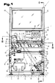
- This device 1 consists of a machine frame 3, which is supported above the height adjustable support feet 4 on a contact surface 5, for example a floor of a workshop.
- a conveyor device 6 is mounted on the machine frame 3 and has a revolving conveyor belt 7 with drivers 8 arranged thereon. In the present case, the conveyor device 6 is designed in the manner of an elevator conveyor.
- the conveyor belt 7 is driven by a drive motor 9 in the direction indicated by an arrow and extends from a receiving chute 10, in which a feed device 11 is arranged, into the area of a deflecting chute 12.
- This deflecting chute 12 is arranged downstream of a linear conveyor device 13.
- the linear conveyor device 13 consists of individual conveyor lines 14, 15, 16, in which using known components, such as balancing webs and or or Deflectors and / or calibres an alignment or sorting of the individual parts 2 is carried out in the direction of an arrow 17.
- the transport of the individual parts 2 in the conveyor lines 14 to 16 or in the region of the deflection chute 12 takes place by means of vibration drives 18, which are fastened on a base body 19, which is arranged via vibration damping devices 20, on a base plate 21 fastened to the machine frame 3.
- the base plate 21 can be aligned to different positions with respect to the contact surface 5 - for example parallel or inclined in the conveying direction corresponding to the arrow 17.
- An intermediate store 23 is also arranged on the machine frame 3 for supplying compressed air and for controlling the individual drives or cylinders, said intermediate store being connected via a line 24 to a central compressed air supply system.
- a maintenance unit 25 and a pneumatic control 26 are connected to the intermediate store 23 via lines, as are valves 27, operating and display elements 28.
- the pneumatic control 26 is connected to the maintenance unit 25 and a lifting drive 30 for the feed device 11 via lines 29, indicated schematically by dash-dotted lines , which consists of a chute bottom 31 or the plate forming this, is fastened at its end distanced from the conveyor belt 7 to the machine frame 3 so as to be pivotable about an axis 32 and can be operated with the lifting drive 30, which is closer to the conveyor belt 7 in a region distanced from the axis 32 is arranged to be adjusted from a rest position drawn in full lines to a raised position schematically indicated in dashed lines.
- the movement of the plate should enable the individual parts 2 to be replenished in the direction of the conveyor belt 7.
- a storage 34 arranged upstream of the receiving chute 10 and arranged as an interchangeable container 33, which can be connected to the receiving chute 10 via an outlet 35.
- slides 36, 37 are arranged displaceably in height guideways 38, 39 in order to regulate or prevent the supply of individual parts 2 into the receiving chute 10.
- the individual parts 2 conveyed by the drivers 8 of the conveyor belt 7 are deflected in their conveying direction by approximately 90 degrees and are conveyed by gravity through the deflecting chute 12 designed as a chute to a vibration conveyor 40, the conveying direction of the individual parts 2 deflected by a further 90 degrees in the direction of the storage 34 and roughly aligned during transport by baffle elements 41 arranged in the vibration conveyor 40 and fed to the conveying path 14, 15, 16.
- the vibration conveyor 40 is mounted on the base plate 21 so as to be adjustable in height via a height adjusting device 42.
- a vibration damping system 43 for example a roller bearing bed, prevents vibrations from being transmitted to the machine frame 3.
- the conveyor lines 14, 15, 16 are held in a motionally connected manner on a common support body 46 via coupling devices 44 and adjusting and adjusting devices 45 and along the conveying direction via the vibration drives 18 - arrow 17 - Relatively movable to the base body 19.
- the vibration drives 18 can be designed as throwing conveyors or with a horizontal oscillating movement as a sliding conveyor.
- the machine frame 3 formed by a C-profile 47 forms corner posts 49, 50 on both sides of an operating opening for the arrangement of height guideways 51, 52 for a security door 53, which relieves the weight via a known arrangement of counterweights 54 and monitors its position via door contacts 55 and is displayed if necessary.
- the linear conveyor device 13 of the device 1 is shown. It comprises three areas of conveyor lines 14, 15, 16, which form a function module 56 for pre-orienting individual parts 2, a function module 57 for arranging and aligning the individual parts 2 and a functional module 58 for conveying and storing the individual parts 2.
- the functional modules 56 to 58 are arranged on the common support body 46 via adjusting and adjusting devices 45.
- the support body 46 forms with the vibration drives 18, which e.g. have as an oscillator an electromagnet 59, the known vibration conveyor 40 for conveying the individual parts 2 in the direction of arrow 17 from a feed point 60 to a removal point 61.
- the functional module 56 into which the individual parts 2 pass via the deflection chute 12 designed as a gravity slide, has deflection blocks 62 in the conveying direction - arrow 17 - by means of which the individual parts 2 are brought into a pre-oriented position by the conveying force acting on them.
- the individual parts 2 are aligned and arranged in a specific position by the deflectors 64, 65 arranged on a guide track 63, which protrude into the conveying path of the individual parts 2. In this case, not pre-oriented individual parts 2 are thrown out of the guideway 63 in the region of recesses 66 from the guideway 63. These individual parts 2 are via a discharge line 67, a collecting container 68 and or or via a return conveyor, for example one Conveyor belt, the memory 34 fed. This ensures that the individual parts 2 of the further guideway 69 of the functional module 58 are fed in an aligned and defined position.
- the guideways 63, 69 are arranged inclined in the conveying direction - arrow 17 - so that the effect of the vibration conveyor 40 is increased. As a result, the performance of the vibration conveyor 40 can be adapted to the removal cycle for the individual parts 2.
- the adjusting and adjusting device 45 which in the embodiment shown is formed by adjusting screws, makes it possible to quickly retrofit the vibration conveyor 40 for different capacities.
- the individual parts 2 are lined up closely in the guideway 69, a separating device 70 arranged in the region of the removal point 61, e.g. a pneumatically operated stop stop 71, which separates the individual parts 2 in the removal cycle and at a removal position 72, e.g. for a gripper 73 on a guideway section 74.
- a sensor 75 e.g. A dynamic pressure interrogation device can be monitored at the take-off position 72 whether an individual part 2 is present or.
- the adjusting and adjusting devices 45 are shown as adjusting screws 76, the coupling devices 44 being formed by screw heads 77 which, like sliding blocks, are open at an upward angle and at an angle of 90 degrees to the conveying direction - arrow 17 - arranged, C-shaped profile 78 are guided. Parallel to the conveying direction - arrow 17 - a further upwardly open C-shaped profile 79 is mounted on the set screws 76, on which holders 80, 81 for the guideways 63, 69 are arranged.
- the actuating and adjusting devices 45 in contrast to those shown in FIGS. 4 and 5, can be replaced by actuating elements which enable an automated actuating process, e.g. cylinders and / or electrically operated threaded spindles or actuating elements with a similar function.
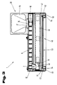
- FIGS. 6 and 7 show two cross-sectional areas of the linear conveyor device 13, the same reference numerals being used for the same parts already described in FIGS. 1 to 5.
- the 6 shows the guideway 63 following the pre-orienting section.
- the individual parts 2 are moved by gravity in the deflection chute 12 designed as a slide in the direction of the guideway 63.
- the vibration which causes the individual parts 2 to move in the direction of the conveying direction - arrow 17 - causes the individual parts 2 to be deflected by approximately 90 degrees, the deflection blocks 62 arranged in a slideway 82 enabling the individual parts 2 to be pre-oriented.
- the individual parts 2 arrive in a receptacle 83 of the guideway 63.
- An inlet opening 84 of the guideway 63 is above a Support body 46 arranged, wedge-shaped, in the direction of the deflection chute 12 inclined discharge path 85 is arranged.
- FIG. 7 shows a section in the area of the functional module 58 with the guide track 69 for individual parts 2 of the linear conveyor device 13.
- a coupling device 44 which e.g. is formed from ball locking elements 88
- the profile 78 e.g. a C-shaped profile arranged at right angles to the conveying direction.
- the profile 79 is supported on the profile 78 via the height adjustment device 42, on which a holding element 89 for a deflection rail 90 arranged in the region of the guide track 69 and forming a height limitation for the individual parts 2 is fastened.
- the guide track 69 is formed from track parts 91, 92 which delimit a free space 93 for the individual parts 2.
- the web parts 91, 92 in the direction of the double arrows 94, 95, it is possible to adapt the width of the free space 93 to the individual parts 2 transversely to the conveying direction.
- the height adjusting device 42 it is also possible to change the height of the free space 93 for the individual parts 2. This possibility of adjusting the free space 93 enables the linear conveyor device 13 to be quickly adapted to different dimensions of the individual parts 2.
- control elements such as cylinders, magnets, spindle motors, etc.
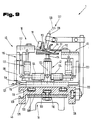
- the removal point 61 of the linear conveyor device 13 with the guideway section for the individual parts 2 is shown in FIG.
- the individual parts 2 are positioned in a recess adapted to the geometry of the individual parts 2 at the removal position 72 by the stop stop 71, the sensor 75, e.g. an air nozzle 96 of a dynamic pressure monitoring device 97 monitors the presence of an individual part 2.
- the separating device 70 is arranged upstream of the removal position 72 in the conveying direction - arrow 17, as a result of which the individual parts 2 already arrive in the removal position 72 from where they e.g. removed by the gripper 73 and fed to a processing position or assembly point.
- the individual parts 2 can also be separated in the region of the removal position 72.
- An angled lifting element 98 which is arranged via a clamping block 99 and a guide rod 100 on a cylinder head plate 101 of a compressed air cylinder 102, for example a short-stroke cylinder, lifts the individual part 2 from the guide area of the guide track sections 74 into the area of the gripper jaws 103.
- the lifting element forms 98 with its fastening leg 104, a stop 105 for the further individual parts 2 fed by the linear conveyor device 13. If the individual part 2 is taken over by the tong gripper 73 and the lifting element 98 is returned to its original position, a further individual part 2 can run onto the lifting element 98. This ensures that the individual parts 2 are removed in cycles for processing and / or assembling the individual parts 2.
- the lifting element 98 can be adapted to changed removal positions for the individual parts 2.
- a drive device e.g. a pressurized cylinder or a spindle motor
- the adjustment of the lifting element 98 to variable removal positions 72 is carried out automatically.
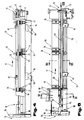
- FIGS. 9 and 10 show a cross-sectional area of the conveyor section 16 with the guideway section 74 for storing the individual parts 2.
- the support body 46 which is arranged on vibration drives 18, for example vibrating magnets, has a C-shaped cross section. T-shaped grooves 109 for sliding blocks 110 are arranged in the web 108 in the longitudinal direction of the support body 46 and are used to fasten the support body 46 to the vibration drives 18 and the adjusting and adjusting devices 45 for the height guide track 51, as well as a deflector 64 and a guide plate 111 serve.
- the height guide track 51 is formed, for example, from a sheet metal strip 112 running in the longitudinal direction of the conveyor section 16 and a run-up wedge 113 arranged thereon, and is supported in height-adjustable manner via the height adjustment device 42, for example an adjusting screw 114 on the support body 46.
- the adjusting and adjusting devices 45 for the deflector 64 and the guide plate 111 are formed from L-shaped angular parts 116, 117 which can be adjusted in guide arrangements 115 in their relative position to one another.
- a base leg 118 is displaceably guided in the direction of a double arrow 121 in a guide arrangement 119 with respect to a support part 120 arranged on the support body 46 at right angles to the feed device of the conveying path.
- the adjusting and adjusting device 45 is provided with actuating members 123, 124, for example pressurized cylinders, which automatically adjust the adjusting and adjusting device 45 between two end positions, as shown by the illustration in full and in dash -Dotted lines allow.
- actuators such as stepper motors with spindle drives, can also be used in order to be able to move to any position between the two end positions. This enables the device 1 to be quickly converted for processing different individual parts 2.
- monitoring elements 127 for example inductive sensors 128, which are connected to a control device via lines 129, can be arranged via adjustable holding elements.
- the linear conveyor device 13 is shown in a schematic representation in FIG. 11.
- mounting brackets 131 with their legs relative to one another are arranged in an elongated hole arrangement 130 in the vertical direction.
- the legs of the mounting bracket 131 form supports for the base plate 21.
- the size of the pendulum-like movements of the base body 19 is limited on the one hand by the diameter of the roller bodies 132 and the recesses 134, 135 assigned to them in the base plate 21 and the base body 19 and is approximately between 2 and 6, preferably 4 mm.
- the vibration drive 18 is formed on the base body 19, for example arranged by an electromagnet for the deflection chute 12.
- the vibration damping system 43 for the deflection chute 12 is arranged via the height adjusting device 42, for example a threaded spindle 136, which is adjustable in height.
- the vibration drives 18 for the support body 46 are formed on the base body 19, for example by means of the C-profile 47 for the actuating and adjusting devices 45 and the coupling devices 44 for the conveyor lines 14, 15, 16.
- the adjusting and adjusting devices 45 are e.g. formed by compressed air cylinders 102 which can be acted upon by compressed air and which can assume two end position positions via control commands and thus enable the linear conveyor device 13 to be rapidly adapted to different operating conditions for different individual parts 2.
- compressed air cylinder 102 steplessly adjustable control elements, such as Spindle drives operated via stepper motors are used in order to be able to better adapt the linear conveyor device 13 to the different operating conditions.
- the conveying path 14 forms the rough-animal path for the individual parts 2.
- baffles 111 are arranged in the region of the guideway, so that the individual parts 2 in a predetermined position are caused by the vibratory drives 18 in the region of the rough-animal path to position.
- unoriented individual parts 2 are sorted out of the conveying path and from there, for example, via the conveyor belt 86 back to the store.
- the position of the guide plate 111 can be varied, for example, via an adjusting element 138 in order to adapt the linear conveyor device 13 to different individual parts 2.
- 11 shows the orientation of the individual parts 2 in simplified form by the guide plate 111, as is very much the case for orientation simple parts 2 is sufficient. In practice, these guide plates 111 are replaced by corresponding baffle elements 139 for difficultly shaped individual parts 2.
- baffle elements can be made from spatially deformable sheet metal or plastic lamellae, each lamella being assigned its own drive similar to a dot matrix printer, whereby great flexibility is achieved through short changeover times.
- the oriented individual parts 2 arriving from the conveyor section 15 are arranged and strung together and the presence of the individual parts 2 is monitored by a sensor 140.
- a sensor upstream of the sensor 140 it is also possible to monitor the number of individual parts 2 that are pent up in the ordered state and to temporarily stop the linear conveyor device 13 via a controller 141 when the storage area is full.
- 11 also shows the pneumatic control 26 with the valves 27 for actuating the pressurized elements, such as the compressed air cylinder 102, for which purpose these are connected to the pneumatic control 26 via compressed air lines 142 and this via compressed air lines 143 to a pressure supply system 144 formed by a Compressor 145 and an accumulator 146 are connected.
- valves 27 are connected to the control 141, e.g. a freely programmable controller.
- control units e.g. a freely programmable controller.
- control units with a computer unit 148, which is formed from a central computer 149 and an input terminal 150 with a screen 151.
- Such a configuration will be expedient, in particular when several linear conveyor devices 13 of the same type are operated in parallel, for bringing together a larger number of different individual parts 2 to form a central processing and / or assembly station, because this enables the central control and monitoring of all linear conveyor devices 13 as a function of the processing and or or assembly station is possible.
- any feed devices for the assembly parts in front of or behind the linear conveyor devices according to the invention, e.g. Whirl chambers, drum feeders, disentangling devices, etc.
- the individual orientation, sorting, separating devices and deflectors, baffles and ejection openings or the like can be arranged as desired on the guideways of the vibrating base body.
Description
Die Erfindung betrifft eine Linearfördereinrichtung für Einzelteile mit Vorrichtungen zum Ausrichten und gegebenenfalls Sortieren sowie zum lagerichtigen Führen und gegebenenfalls Speichern, deren Einlaß einem Auslaß einer Fördervorrichtung zum Transport einer Teilmenge von ungeordneten Einzelteilen nachgeordnet ist und deren dem Einlaß gegenüberliegender Endbereich einer Entnahmevorrichtung zugeordnet ist und mit einer aus mehreren, in Förderrichtung der Einzelteile hintereinander angeordneten Funktionsmodulen bestehenden Führungsbahn für die Einzelteile, die jeweils über eine lösbare Kupplungsvorrichtung auf einem Tragkörper befestigt sind, die über einen Antrieb auf einem Basiskörper abgestützt sind.The invention relates to a linear conveying device for individual parts with devices for aligning and, if necessary, sorting and for guiding and storing, if appropriate, the inlet of which is arranged downstream of an outlet of a conveying device for transporting a subset of disordered individual parts and whose end region opposite the inlet is assigned to a removal device and with a consisting of a plurality of function modules arranged one behind the other in the conveying direction of the individual parts, for the individual parts, each of which is fastened to a support body via a releasable coupling device and which is supported on a base body via a drive.
Eine Vorrichtung zum gerichteten, einzelnen Zuführen von Teilen zu Entnahmestationen ist aus der AT-B-341 426 des gleichen Anmelders bekannt. Dabei ist zwischen einer Aufgabestation und einer Entnahmestation ein Förderweg mit aufeinanderfolgenden, die Teile ausrichtenden Einzelförderern angeordnet. Die Aufgabestation weist einen Auslaß zur dosierten aber ungeordneten Abgabe der in einer Wirrlage befindlichen Teile auf. Die zur Ausrichtung der Einzelteile vorgesehenen Linearförderer sind in etwa horzizontal und hintereinander angeordnet und weisen Abscheider wie z.B. Schikanen, Balancierstäbe, Abweiser oder dgl. auf, um jene Teile auszuschneiden, die einem bestimmten Ausrichtungs- bzw. Vereinzelungszustand nicht entsprechen. Jeder der einzelnen Funktionsmodule bzw. Einzelförderer ist über eine einzelne lösbare Kupplungsvorrichtung mit einem bzw. mehreren elektrischen Vibratoren verbunden. Diese Vibratoren sind über verstellbare Grundplatten auf einer gemeinsamen Tischplatte gehaltert. Somit sind die einzelnen Funktionsmodule voneinander in ihrer Wirkungsweise getrennt und es bedarf jeder der einzelnen Funktionsmodule mit seinem zugeordneten Vibrator bzw. Vibratoren eines eigenen Abstimmungsvorganges.A device for the directed, individual feeding of parts to removal stations is known from AT-B-341 426 by the same applicant. A conveying path with successive individual conveyors that align the parts is arranged between a loading station and a removal station. The feed station has an outlet for the metered but unordered delivery of the parts in a tangled position. The linear conveyors provided for the alignment of the individual parts are arranged approximately horizontally and one behind the other and have separators such as, for example, baffles, balancing bars, deflectors or the like, in order to cut out those parts which do not correspond to a particular alignment or separation state. Each of the individual functional modules or individual conveyors is connected to one or more electrical vibrators via a single detachable coupling device. These vibrators are mounted on a common table top via adjustable base plates. The individual functional modules are thus separated from one another in their mode of operation and each of the individual functional modules with its associated vibrator or vibrators requires its own coordination process.
Bekannte Vibrationsfördereinrichtungen - gemäß DE-PS 25 52 763 - umfassen eine Platte, deren Oberseite ein Profil mit sägezahnartigem Querschnitt, also Längsrinnen aufweist. Durch Abfräsungen dieser Längsrinne in einem vorbestimmten Längsbereich wird ein Balanciersteg gebildet. Teile, die nicht über ihre ganze Länge auf dem stehengebliebenen Teil der Längsrinne aufliegen, fallen seitlich herab. Weiters sind auf der mit einem Vibrationsantrieb in Schwingungen versetzten Platte den Längsrinnen Aufsatzteile zugeordnet, die Abweiser bilden, sodaß nach oben weisende Teile der Montageteile erfaßt werden und diese entweder in die richtige Lage gedrückt oder ausgeworfen werden. Derartige Vibrationsfördereinrichtungen haben sich in der Praxis bewährt, die Herstellung der Platten mit den darauf angeordneten Balancierstegen sowie den Abweisern ist jedoch sehr arbeitsaufwendig und muß äußerst exakt durchgeführt werden, und es ist schwierig, Teile, die nach unten vorragende Enden aufweisen, zuzuführen.Known vibration conveying devices - according to DE-PS 25 52 763 - comprise a plate, the upper side of which has a profile with a sawtooth-like cross section, that is to say longitudinal channels. A balancing web is formed by milling this longitudinal channel in a predetermined longitudinal region. Parts that do not rest on the remaining part of the longitudinal channel over their entire length fall down to the side. Furthermore, on the plate set in vibration with a vibration drive, the longitudinal channels are assigned attachment parts which form deflectors, so that parts of the mounting parts pointing upwards are grasped and these are either pressed into the correct position or ejected. Vibration conveyors of this type have proven themselves in practice, but the manufacture of the plates with the balancing webs arranged thereon and the deflectors is very labor-intensive and must be carried out extremely precisely, and it is difficult to feed parts which have downwardly projecting ends.
Bei einer weiteren bekannten Vibrationsfördereinrichtung - DE-AS 12 74 981 - weist die Vibrationsfördereinrichtung einen aus Gitterstäben gebildeten Rost auf. Der Rost wird über einen Vibrationsantrieb insgesamt in Schwingungen versetzt, sodaß sich die Teile, die einen Kopfdurchmesser aufweisen, der größer ist als dessen Schaftdurchmesser, mit ihren Köpfen auf den einander benachbarten Gitterstäben aufhängen. Dazu sind die Rostspalten zwischen den einzelnen Gitterstäben größer als der Schaftdurchmesser der Montageteile, jedoch kleiner als deren Kopfdurchmesser. Diese Vibrationsfördereinrichtung ist nur für wenige, ganz spezifisch ausgebildete Teile einsetzbar, da beispielsweise bei einer Änderung des Schaftdurchmessers der zu verarbeitenden Montageteile ein völlig neuer Gitterrost erstellt werden muß.In another known vibration conveyor device - DE-AS 12 74 981 - the vibration conveyor device has a grate formed from bars. The grate is made to vibrate as a whole by means of a vibration drive, so that the parts which have a head diameter which is larger than its shaft diameter hang with their heads on the adjacent lattice bars. For this purpose, the grating gaps between the individual bars are larger than the shaft diameter of the assembly parts, but smaller than their head diameter. This vibration conveyor can only be used for a few, very specifically designed parts, since, for example, a completely new grating has to be created when the shaft diameter of the assembly parts to be processed is changed.
Aus der GB-PS 963 835 ist eine Vibrationsfördereinrichtung bekannt, die einen Vorratsbehälter und zwei, diesem hintereinander nachgeordnete und parallel zueinander verlaufende Förderbahnteilstücke aufweist. Das dem Vorratsbehälter unmittelbar nachgeordnete Förderbahnteilstück ist mit einem Vibrationsantrieb gekuppelt. In dem nachgeordneten anderen Förderbahnteilstück erfolgt die Förderung nur durch Schwerkraft, wodurch Stauungen nicht vermieden werden können.From GB-PS 963 835 a vibration conveyor device is known which has a storage container and two conveyor track sections arranged one behind the other and running parallel to one another. The conveyor track section immediately downstream of the storage container is coupled to a vibration drive. In the other section of the conveyor track located downstream, it is only conveyed by gravity, so that congestion cannot be avoided.
Der Erfindung liegt die Aufgabe zugrunde, eine Linearfördereinrichtung für die Förderung von Montageteilen zu schaffen, die mit einfachen Mitteln an die Verarbeitung unterschiedlicher Montageteile angepaßt werden kann und deren Herstellung auch ohne die genaue Kenntnis der zu verarbeitenden Teile möglich ist.The invention has for its object to provide a linear conveyor for the promotion of assembly parts that with simple means the processing of different assembly parts can be adapted and their production is possible even without the exact knowledge of the parts to be processed.
Diese Aufgabe der Erfindung wird bei der Linearfördereinrichtung gemäß Anspruch 1 insbesondere dadurch gelöst, daß dem Auslaß der vorgeordneten Fördereinrichtung ein Funktionsmodul zur Grobausrichtung der Einzelteile diesem ein Funktionsmodul zum Ordnen, Ausrichten und gegebenenfalls Sortieren nachgeordnet ist, an welches ein Funktionsmodul zum Längstransport und gegebenenfalls Speichern der Einzelteile anschließt und daß die Funktionsmodule auf einem für alle gemeinsamen Tragkörper angeordnet sind und jedes der Funktionsmodule unabhängig vom anderen mit dem vibrationsangetriebenen Tragkörper über die lösbare Kupplungsvorrichtung verbunden ist. Die ermöglicht mit geringen Umrüstzeiten das Verarbeiten von unterschiedlich ausgebildeten Montageteilen mit der erfindungsgemäßen Linearfördereinrichtung. Gleichzeitig ist es möglich, die Funktionsmodule zum Grobausrichten, Ordnen, Ausrichten und gegebenenfalls Sortieren in Serien vorzufertigen, was insgesamt eine Herstellung solcher Module zuläßt. Darüber hinaus kann bei derartigen Seriengeräten auch ein hoher technischer Standard erreicht werden, der die Betriebssicherheit solcher Fördereinrichtungen erhöht. Die Anpassung der Linearfördereinrichtung an unterschiedliche Einzelteile kann auf den jeweiligen Bedarf sehr einfach ohne aufwendige Umrüst- und Justierarbeiten vorgenommen werden. Dadurch ist das Abstimmen der Funktionsmodule zueinander, welches für einen stau- und damit störungsfreien Betrieb solcher Fördereinrichtungen maßgeblich ist, und daher auch ein Umrüsten solcher Anlagen auf unterschiedliche Arten von zu fördernden Einzelteilen schnell durchführbar.This object of the invention is achieved in the linear conveyor device according to
Von Vorteil ist es aber auch, wenn die Kupplungsvorrichtungen der Funktionsmodule gleichartig ausgebildet sind, weil durch die Verwendung gleichartiger Kupplungsvorrichtungen an den Funktionsmodulen Fehler und damit Störungen an solchen Anlagen wirkungsvoll verhindert werden können. Dadurch ist eine hohe Verfügbarkeit von solchen Anlagen im allgemeinen in nachgeschalteten, umfangreichen Montagesystemen und geringe Montagekosten erzielbar.However, it is also advantageous if the coupling devices of the functional modules are of the same design, because errors and thus malfunctions in such systems can be effectively prevented by using similar coupling devices on the functional modules. As a result, high availability of such systems can generally be achieved in downstream, extensive assembly systems and low assembly costs.
Es ist aber auch möglich, daß die Kupplungsvorrichtungen zwischen den Funktionsmodulen und dem Tragkörper durch in den Tragkörper vorgesehene Längsschlitze und mit den Funktionsmodulen verbundene Gleitsteine gebildet sind, wodurch ein sehr variables Kupplungssystem für den Aufbau der Funktionsmodule auf dem Tragkörper erreicht wird.However, it is also possible for the coupling devices between the functional modules and the support body to be provided in the support body Longitudinal slots and sliding blocks connected to the functional modules are formed, as a result of which a very variable coupling system for the construction of the functional modules on the support body is achieved.
Nach einer anderen Ausführungsvariante ist vorgesehen, daß die Kupplungselemente der Kupplungsvorrichtung über Stell- und Justiereinrichtungen mit den Funktionsmodulen und bzw. oder dem Tragkörper verbunden sind. Durch diese Verstellvorrichtungen können die Funktionsmodule automatisch auf diese vorgegebene Werte verstellt werden, was ein rasches Umrüsten solcher Linearfördereinrichtungen ermöglicht.According to another embodiment variant, it is provided that the coupling elements of the coupling device are connected to the functional modules and / or the support body via adjusting and adjusting devices. By means of these adjustment devices, the function modules can be automatically adjusted to these predetermined values, which enables such linear conveyor devices to be quickly converted.
Nach einer weiteren Ausführungsvariante ist vorgesehen, daß der Basiskörper über eine Schwingungsdämpfungsvorrichtung mit Dämpfungselementen auf einem Maschinengestell befestigt ist, wodurch die Fördereinrichtungen insgesamt sehr geringe Lärmemmissionen verursachen.According to a further embodiment variant, it is provided that the base body is attached to a machine frame by means of a vibration damping device with damping elements, as a result of which the conveying devices cause very low overall noise emissions.
Vorgesehen ist aber auch, daß die Höhenführungsbahn für die Einzelteile in den einzelnen Funktionsmodulen unterschiedlich stark in Förderrichtung gegenüber dem Basiskörper geneigt angeordnet sind. Damit ist es möglich, entsprechend der Orientierung der Teile auf der Höhenführungsbahn, z.B. der Dimensionsänderung bei unterschiedlichen Höhen und Längen Rechnung tragend, unterschiedliche Vorschubgeschwindigkeiten für die Teile zu erzielen und so einen einheitlichen Materialfluß über die gesamte Linearfördereinrichtung zu erreichen.However, it is also provided that the height guide track for the individual parts in the individual functional modules are arranged at different degrees of inclination in the conveying direction with respect to the base body. This makes it possible, depending on the orientation of the parts on the height guide, e.g. taking into account the dimensional change at different heights and lengths, to achieve different feed speeds for the parts and thus to achieve a uniform material flow over the entire linear conveyor.
Es ist aber auch vorteilhaft, wenn das Maschinengestell durch ein vertikal ausgerichtetes Profil mit etwa C-förmigem Querschnitt gebildet ist, weil dadurch eine sehr steife Ausbildung des Maschinengestelles, welche den Vibrationsbeeinflussungen einen hohen Widerstand entgegensetzt, erreichbar ist.However, it is also advantageous if the machine frame is formed by a vertically oriented profile with an approximately C-shaped cross-section, because a very rigid construction of the machine frame, which counteracts the vibration influences with a high resistance, can thereby be achieved.
Wie es weiters von Vorteil ist, wenn der Basiskörper auf jener Seite des Maschinengestells angeordnet ist, auf welcher die Schenkel des C-förmigen Profils über die Profilbasis vorragen. Dadurch sind die Funktionsteile der Linearfördereinrichtung im Maschinengestell einfach zu lagern, können darüber hinaus für das Justieren dieser Teile sehr gut zugänglich positioniert werden und weiters durch entsprechende Abschottungselemente gegenüber unbefugten Zugriff geschützt und gesichert werden.As is also advantageous if the base body is arranged on that side of the machine frame on which the legs of the C-shaped profile protrude above the profile base. As a result, the functional parts of the linear conveyor device are easy to store in the machine frame, can also be positioned very easily for the adjustment of these parts and can also be protected and secured against unauthorized access by appropriate partitioning elements.
Eine andere Ausführungsvariante sieht vor, daß die Fördereinrichtung für die Teilmengen der Einzelteile sowie ein Behälter zur Aufnahme der ungeordneten Menge von Einzelteilen auf der vom Basiskörper abgewendeten Seite der Basis des durch ein C-förmiges Profil gebildeten Maschinengestells angeordnet sind, wodurch diese Fördereinrichtungen insgesamt kompakte Außenabmessungen haben, wodurch sich auch die Gesamtabmessungen von durch mehrere Linearfördervorrichtungen zu bedienende Montageautomaten bzw. Fertigungseinrichtungen klein und damit platzsparend gehalten werden können. Darüber hinaus schafft diese Anordnung eine klare Auftrennung der Baugruppen und der Funktionsteile, was für die Wartung und die Bedienung der Funktionsgruppen von Vorteil ist.Another embodiment variant provides that the conveying device for the partial quantities of the individual parts and a container for holding the disorderly quantity of individual parts are arranged on the side of the machine frame formed by a C-shaped profile facing away from the base body, as a result of which these conveying devices have compact overall dimensions have, whereby the overall dimensions of assembly machines or production facilities to be operated by several linear conveying devices can be kept small and thus space-saving. In addition, this arrangement creates a clear separation of the assemblies and the functional parts, which is advantageous for the maintenance and operation of the functional groups.
Weiters ist es vorteilhaft, wenn die Fördereinrichtung und der Behälter für die ungeordnete Menge der Teile parallel zur Förderrichtung der Funktionsmodule ausgerichtet und insbesondere entgegen der Förderrichtung anschließend an das Funktionsmodul zur Vororientierung angeordnet ist. Dies ermöglicht ein unmittelbares Zurückführen von nicht richtig geordneten Einzelteilen unmittelbar vor dem Bereich der Vereinzelung in den Behälter für die ungeordnete Menge, wodurch zusätzliche Fördereinrichtungen eingespart werden.Furthermore, it is advantageous if the conveying device and the container for the unordered quantity of parts are aligned parallel to the conveying direction of the functional modules and, in particular, is arranged opposite the conveying direction to the functional module for pre-orientation. This enables a direct return of improperly ordered individual parts directly in front of the area of the separation into the container for the unordered quantity, thereby saving additional conveying devices.
Möglich ist aber auch, wenn in den über die Basis des C-förmigen Profils vorspringenden Schenkeln Führungs- und/oder Antriebsvorrichtungen einer höhenverstellbaren Sicherheitstüre angeordnet sind. Dadurch können die Einrichtungen zum Absichern der Funktionsteile, wie z.B. Sicherheitstüren und bzw. oder Verkleidungselemente einfach angeordnet werden, wodurch weitere Befestigungselemente bzw. Konstruktionsteile erspart werden.However, it is also possible if guide and / or drive devices of a height-adjustable safety door are arranged in the legs projecting over the base of the C-shaped profile. As a result, the devices for securing the functional parts, e.g. Security doors and / or cladding elements can be easily arranged, which saves additional fasteners or structural parts.
Es ist aber auch vorteilhaft, wenn die Funktionsmodule zwischen der Sicherheitstüre und der Basis des das Maschinengestell bildenden C-förmigen Profils angeordnet ist, weil dadurch das Maschinengestell eine geschlossene Kabinenform darstellt, innerhalb der die Funktionsmodule geschützt sind und Beeinflussungen der Umgebung, insbesondere Lärmbeeinflussungen wirkungsvoll vermieden werden.However, it is also advantageous if the functional modules are arranged between the security door and the base of the C-shaped profile forming the machine frame, because this makes the machine frame a closed cabin shape within which the functional modules are protected and effectively avoid influences on the environment, in particular noise influences will.
Nach einer weiteren Ausführungsvariante ist vorgesehen, daß das Funktionsmodul zum Ordnen und Ausrichten der Einzelteile über einen Rückförderweg mit einem Sammelbehälter für die ausgeschiedenen Einzelteile versehen ist. Dadurch wird es möglich, die Linearfördereinrichtung mit dem Behälter für die ungeordneten Einzelteile räumlichen Anordnungsgegebenheiten anzupassen.According to a further embodiment variant, it is provided that the functional module for arranging and aligning the individual parts via a return path is provided with a collecting container for the separated individual parts. This makes it possible to adapt the linear conveyor device with the container for the disordered individual parts to spatial arrangement conditions.
Es ist aber auch möglich, daß der Sammelbehälter durch den Wechselbehälter für die ungeordnete Menge der Teile gebildet ist, wodurch ein zusätzlicher Aufnahmebehälter und eine auch damit verbundene manuelle Teilemanipulation bei der Umrüstung solcher Linearfördereinrichtungen entfällt.However, it is also possible for the collecting container to be formed by the interchangeable container for the unordered quantity of the parts, as a result of which an additional receiving container and an associated manual parts manipulation when converting such linear conveying devices are dispensed with.
Wie es weiters nach einer vorteilhaften Ausführungsvariante möglich ist, daß die Rückfördervorrichtung durch einen Schwenkförderer gebildet ist, der eine zur Förderrichtung der Funktionsmodule unterschiedliche Förderrichtung aufweist, wodurch es beispielsweise möglich ist, die am Funktionsmodul für das Ordnen ausgeschiedenen Teile zu prüfen und mit dem Schwenkförderer entsprechend dem Ergebnis der Prüfung in unterschiedliche Aufnahmebehälter rückzuführen, um so eventuell festgestellte Schlechtteile auszusondern.As is also possible according to an advantageous embodiment variant, that the return conveyor device is formed by a swivel conveyor which has a different conveying direction to the conveying direction of the functional modules, which makes it possible, for example, to check the parts which have been eliminated on the functional module for organization and accordingly with the swivel conveyor return the result of the test to different receptacles in order to separate out any bad parts that may have been found.
Nach einer weiteren Ausführungsvariante ist vorgesehen, daß im Bereich des das Maschinengestell bildende C-förmigen Profiles Versorgungseinrichtungen, insbesondere für die Versorgung mit Druckluft und bzw. oder elektrischer Energie unter- und bzw. oberhalb des Basiskörpers des Linearförderers angeordnet sind. Durch diese Anordnung werden sehr kurze Versorgungsleitungen zu den Funktionsmodulen erreicht, was sich vorteilhaft für die Montage aber auch für die Betriebssicherheit dieser Linearfördereinrichtungen auswirkt.According to a further embodiment variant, provision is made for supply devices, in particular for the supply of compressed air and / or electrical energy, to be arranged below and / or above the base body of the linear conveyor in the region of the C-shaped profile forming the machine frame. With this arrangement, very short supply lines to the functional modules are achieved, which has an advantageous effect on the assembly but also on the operational safety of these linear conveyor devices.
Wie es weiters möglich ist, daß im Bereich des C-förmigen Profiles oberhalb der Funktionsmodule Einrichtungen der elektrischen und bzw. oder pneumatischen Steuerung der Linearfördervorrichtung angeordnet sind, weil dadurch eine optische Funktionsüberwachung der Linearfördereinrichtung durch Anordnung von Anzeigeinstrumenten und bzw. oder Anzeigeleuchten in für das Überwachen geeigneter Position möglich ist.How it is also possible that devices of the electrical and / or pneumatic control of the linear conveyor device are arranged in the area of the C-shaped profile above the function modules, because thereby an optical function monitoring of the linear conveyor device by arranging display instruments and or or indicator lights in for Monitoring suitable position is possible.
Weiters ist es vorteilhaft, wenn die Stell- und Justiereinrichtungen für die Funktionsmodule aus mit einem unter Druck stehenden Medium beaufschlagten Zylindern und bzw. oder elektrisch betriebenen Antrieben gebildet sind. Dadurch kann ein Umrüsten der Fördereinrichtung für unterschiedliche Einzelteile sehr rasch und ohne Einsatz von Spezialisten zumindest für zwei Einstellungen, welche die Zylinder gegen Endanschläge anfahren, erfolgen.Furthermore, it is advantageous if the adjusting and adjusting devices for the functional modules are made of a medium under pressure acted cylinders and or or electrically operated drives are formed. As a result, the conveying device can be converted very quickly for different individual parts and without the use of specialists for at least two settings which move the cylinders against end stops.
Wie es weiters auch möglich ist, daß die Stell- und Justiereinrichtungen für die Funktionsmodule durch z.B. elektrisch über Schrittmotore betätigte Spindel-antriebe gebildet sind, wodurch sich eine Vielzahl von unterschiedlichen Stellungen ansteuern läßt und dadurch eine wesentlich höhere Variantenzahl von Einzelteilen mit der Linearfördereinrichtung bei geringstmöglichen Umrüstzeiten gefördert werden kann.As it is also possible that the adjusting and adjusting devices for the function modules by e.g. spindle drives actuated electrically via stepping motors are formed, as a result of which a large number of different positions can be controlled and a significantly higher number of variants of individual parts can be conveyed with the linear conveyor device with the shortest possible changeover times.
Nach einer weiteren Ausbildungsvariante ist vorgesehen, daß die Funktionsmodule aus Höhen- und Seitenführungsbahnen gebildet sind und eine Relativverstelleinrichtung für die Höhen- und Seitenführungsbahnen vorgesehen ist. Dadurch ist es neben der Abstimmung der Funktionsmodule zueinander weiters möglich, die Führungsbahnen der Teilegeometrie optimal anzupassen.According to a further embodiment, it is provided that the functional modules are formed from vertical and lateral guideways and a relative adjustment device is provided for the vertical and lateral guideways. As a result, in addition to coordinating the function modules with one another, it is also possible to optimally adapt the guideways to the part geometry.
Wie es weiters auch möglich ist, daß der Seiten- und bzw. oder Höhen- und bzw. oder Relativverstellvorrichtung eine Positioniersteuerung zugeordnet ist und Meß- und Positionsmeldeeinrichtungen vorgesehen sind, wodurch die Umstellung bzw. das Umrüsten nach den jeweiligen Einzelteilen zugeordneten Stellparametern vorgenommen und kontrolliert werden kann.As it is also possible that the side and / or height and / or relative adjustment device is assigned a positioning control and measuring and position reporting devices are provided, whereby the changeover or conversion is carried out and controlled according to the setting parameters assigned to the individual parts can be.
Weiters ist es vorteilhaft, wenn die elektrischen Steuereinrichtungen aus einem Funktionsteil für die Steuerung und einem Funktionsteil für ein Diagnosesystem gebildet sind. Durch die Trennung der Steuerfunktionen von den Überwachungsfunktionen können sehr einfach gegenseitige Beeinflussungen durch Rückkoppelungen und Überlagerungen und damit Fehlfunktionen im Steuerungsablauf wie im Überwachungssystem vermieden werden.Furthermore, it is advantageous if the electrical control devices are formed from a functional part for the control and a functional part for a diagnostic system. By separating the control functions from the monitoring functions, mutual influences by feedback and superimposition and thus malfunctions in the control process and in the monitoring system can be avoided very easily.
Nach einer Ausführungsvariante ist vorgesehen, daß der Funktionsteil für die Steuerung eine z.B. frei programmierbare Steuerung umfaßt, wodurch sich verfahrensbedingte Änderungen im Steuerungsablauf sehr rasch durchführen lassen.According to an embodiment variant, it is provided that the functional part for the control comprises, for example, a freely programmable control, as a result of which process-related changes in the control process can be carried out very quickly.
Es ist aber auch möglich, daß der Funktionsteil für das Diagnosesystem ein Anzeigeelement, z.B. einen Bildschirm und bzw. oder ein Aufzeichnungsgerät, z.B. Streifendrucker, Diskettenstation etc. umfaßt, wodurch eine visuelle Überwachung der Anlage wie auch eine lückenlose Dokumentation der Verfahrensabläufe gegeben ist.However, it is also possible for the functional part for the diagnostic system to have a display element, e.g. a screen and / or a recording device, e.g. Strip printer, diskette station, etc., which provides a visual monitoring of the system as well as a complete documentation of the procedures.
Möglich ist aber auch, daß das Diagnosesystem über eine Fehlerhäufigkeitslogik verfügt, wodurch eine Unterscheidung von anlagebedingten und teilebedingten Unregelmäßigkeiten im Verfahren möglich ist, um eine Klassifizierung der Fehler vorzunehmen.However, it is also possible that the diagnostic system has an error frequency logic, which makes it possible to distinguish between system-related and part-related irregularities in the method in order to classify the errors.
Möglich ist es aber auch, daß die Fehlerhäufigkeitslogik nach Art und Anzahl auftretender Fehler Aufzeichnungs- und bzw. oder Schaltfunktionen auslöst, wodurch ein Fehlertoleranzbereich entsprechend den Anforderungen festgelegt und insgesamt die Verfügbarkeit einer solchen Anlage erhöht werden kann.However, it is also possible that the error frequency logic triggers recording and / or switching functions according to the type and number of errors occurring, as a result of which a fault tolerance range can be defined in accordance with the requirements and the overall availability of such a system can be increased.
Von Vorteil ist aber auch, wenn das Diagnosesystem ein Meßsystem für die Einzelteile, insbesondere für das berührungslose Messen umfaßt, weil dadurch der Teilefluß für die Vornahme von Vermessungsfunktionen nicht unterbrochen werden muß und so die Gesamtkapazität der Förderleistung nicht beeinträchtigt wird.However, it is also advantageous if the diagnostic system comprises a measuring system for the individual parts, in particular for non-contact measurement, because the part flow for performing measurement functions does not have to be interrupted thereby and the overall capacity of the delivery capacity is not impaired.
Zum besseren Verständnis der Erfindung wird diese anhand der in den Zeichnungen dargestellten Ausführungsbeispiele näher erläutert.For a better understanding of the invention, this will be explained in more detail with reference to the exemplary embodiments shown in the drawings.
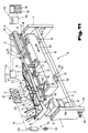
- Fig. 1Fig. 1
- eine erfindungsgemäß ausgebildete Linearfördereinrichtung in Seitenansicht;a linear conveyor device designed according to the invention in side view;
- Fig. 2Fig. 2
- die Linearfördereinrichtung in Seitenansicht, teilweise geschnitten, gemäß den Linien II-II in Fig.1;the linear conveyor in side view, partially in section, according to lines II-II in Fig.1;
- Fig. 3Fig. 3
- die Linearfördereinrichtung nach Fig.1 in Draufsicht, geschnitten, gemäß den Linien III-III in Fig. 1;the linear conveyor according to Figure 1 in plan view, sectioned along the lines III-III in Fig. 1;
- Fig. 4Fig. 4
- eine andere Ausführungsvariante der Funktionsmodule einer erfindungsgemäß ausgebildeten Linearfördervorrichtung in Seitenansicht;another embodiment variant of the functional modules of a linear conveyor device designed according to the invention in side view;
- Fig. 5Fig. 5
- die Funktionsmodule gemäß Fig.4 in Draufsicht;the functional modules according to Figure 4 in plan view;
- Fig. 6Fig. 6
- ein Funktionsmodul in Stirnansicht, geschnitten, gemäß den Linien VI-VI in Fig.5;a functional module in front view, cut, along the lines VI-VI in Figure 5;
- Fig. 7Fig. 7
- ein Funktionsmodul in Stirnansicht, geschnitten, gemäß den Linien VII-VII in Fig.5;a functional module in front view, cut, along the lines VII-VII in Figure 5;
- Fig. 8Fig. 8
- ein Funktionsmodul einer erfindungsgemäß ausgebildeten Linearfördereinrichtung in Stirnansicht, gemäß Pfeil VIII in Fig.5:a functional module of a linear conveyor device designed according to the invention in front view, according to arrow VIII in Figure 5:
- Fig. 9Fig. 9
- eine andere Ausführungsvariante einer Linearfördereinrichtung in Seitenansicht, teilweise geschnitten;another embodiment variant of a linear conveyor in side view, partially sectioned;
- Fig. 10Fig. 10
- die Ausführungsvariante nach Fig.9 in Draufsicht;the embodiment of Figure 9 in plan view;
- Fig. 11Fig. 11
- die Funktionsmodule einer erfindungsgemäß ausgebildeten Linearfördervorrichtung in vereinfachter schematischer, schaubildlicher Darstellung;the functional modules of a linear conveyor device designed according to the invention in a simplified schematic, diagrammatic representation;
In den Fig.1 bis 3 ist eine Vorrichtung 1 zum Ausrichten und bzw. oder Sortieren und gegebenenfalls Vereinzeln von Einzelteilen 2 gezeigt. Diese Vorrichtung 1 besteht aus einem Maschinengestell 3, welches über der Höhe nach einstellbare Stützfüße 4 auf einer Aufstandsfläche 5, beispielsweise einem Boden einer Werkhalle abgestützt ist. Auf dem Maschinengestell 3 ist eine Fördereinrichtung 6 gelagert, die ein umlaufendes Förderband 7 mit auf diesem angeordneten Mitnehmern 8 aufweist. Die Fördereinrichtung 6 ist im vorliegenden Fall in Art eines Elevatorförderers ausgebildet.1 to 3 show a
Das Förderband 7 wird über einen Antriebsmotor 9, in der durch einen Pfeil angedeuteten Richtung umlaufend angetrieben und erstreckt sich von einer Aufnahmeschurre 10, in der eine Zuführvorrichtung 11 angeordnet ist, in den Bereich einer Umlenkschurre 12. Dieser Umlenkschurre 12 ist eine Linearfördervorrichtung 13 nachgeordnet. Die Linearfördervorrichtung 13 besteht aus einzelnen Förderstrecken 14,15,16, in welchen unter Verwendung von bekannten Bauteilen, wie Balancierstegen und bzw. oder Abweisern und bzw. oder Kalibern eine Ausrichtung bzw. Sortierung der Einzelteile 2 auf ihren Transport in Richtung eines Pfeiles 17 erfolgt. Der Transport der Einzelteile 2 in den Förderstrecken 14 bis 16 bzw. im Bereich der Umlenkschurre 12 erfolgt mittels Vibrationsantrieben 18, die auf einem Basiskörper 19 befestigt sind, der über Schwingungsdämpfungsvorrichtungen 20, auf einer am Maschinengestell 3 befestigten Grundplatte 21 angeordnet ist. Über eine Einstellvorrichtung 22 kann die Grundplatte 21 auf unterschiedliche Stellungen gegenüber der Aufstandsfläche 5 - z.B. parallel oder in der dem Pfeil 17 entsprechenden Förderrichtung geneigt - ausgerichtet werden.The conveyor belt 7 is driven by a drive motor 9 in the direction indicated by an arrow and extends from a receiving
Auf dem Maschinengestell 3 ist weiters zur Druckluftversorgung und Steuerung der einzelnen Antriebe bzw. Zylinder ein Zwischenspeicher 23 angeordnet, der über eine Leitung 24 mit einem zentralen Druckluftversorgungssystem verbunden ist. Mit dem Zwischenspeicher 23 ist über Leitungen eine Wartungseinheit 25 und eine Pneumatiksteuerung 26 verbunden sowie Ventile 27, Bedienungs-und Anzeigeorgane 28. Die Pneumatiksteuerung 26 ist über schematisch, durch strichpunktierte Linien angedeutete Leitungen 29 mit der Wartungseinheit 25 und einem Hubantrieb 30 für die Zuführvorrichtung 11, die aus einer einen Schurrenboden 31 bzw. die diese bildende Platte ist an ihrem vom Förderband 7 distanzierten Ende um eine Achse 32 schwenkbar am Maschinengestell 3 befestigt und kann mit dem Hubantrieb 30, der in einem von der Achse 32 distanzierten Bereich näher dem Förderband 7 angeordnet ist, aus einer in vollen Linien gezeichneten Ruhestellung in eine in strichlierten Linien schematisch angedeutete, angehobene Stellung verstellt werden. Durch die Bewegung der Platte soll der Nachschub der Einzelteile 2 in Richtung des Förderbandes 7 ermöglicht werden.An
Auf der von der Linearfördervorrichtung 13 abgewendeten Seite der Fördereinrichtung 6 ist ein der Aufnahmeschurre 10 vorgeordneter, als Wechselbehälter 33 angeordneter Speicher 34 angeordnet, der über einen Auslaß 35 mit der Aufnahmeschurre 10 verbunden werden kann.Arranged on the side of the conveying
Üblicherweise sind im Bereich des Auslasses 35, sowohl im Wechselbehälter 33, wie auch in der Vorrichtung 1 Schieber 36,37 in Höhenführungsbahnen 38,39 verschiebbar angeordnet, um die Zufuhr von Einzelteilen 2 in die Aufnahmeschurre 10 zu regeln bzw. zu verhindern.Usually, in the area of the
In der der Fördereinrichtung 6 nachgeordneten Umlenkschurre 12 werden die durch die Mitnehmer 8 des Förderbandes 7 geförderten Einzelteile 2 in ihrer Förderrichtung um in etwa 90 Grad umgelenkt und durch Schwerkraftförderung durch die als Rutsche ausgebildete Umlenkschurre 12 einem Vibrationsförderer 40 zugeführt, wobei die Förderrichtung der Einzelteile 2 um weitere 90 Grad in Richtung des Speichers 34 umgelenkt und beim Transport durch im Vibrationsförderer 40 angeordnete Schikanenelemente 41 grob ausgerichtet und der Förderstrecke 14,15,16 zugeführt werden. Der Vibrationsförderer 40 ist auf der Grundplatte 21 über eine Höhenstelleinrichtung 42 der Höhe nach einstellbar gelagert. Ein Schwingungsdämpfungssystem 43, z.B. ein Rollenlagerbett verhindert eine Schwingungsübertragung in das Maschinengestell 3. Die Förderstrecken 14,15,16 sind über Kupplungsvorrichtungen 44 und Stell- und Justiereinrichtungen 45 auf einem gemeinsamen Tragkörper 46 bewegungsverbunden gehaltert und über die Vibrationsantriebe 18 längs der Förderrichtung - Pfeil 17 -relativ beweglich zum Basiskörper 19 angeordnet. Die Vibrationsantriebe 18 können als Wurfförderer oder mit einer horizontalen Schwingungsbewegung als Gleitförderer ausgebildet sein.In the deflecting
Das durch ein C-Profil 47 gebildete Maschinengestell 3 bildet beidseits einer Bedienöffnung 48 Ecksteher 49,50 für die Anordnung von Höhenführungsbahnen 51,52 für eine Sicherheitstüre 53 aus, die über eine bekannte Anordnung von Gegengewichten 54 gewichtsentlastend ist und deren Stellung über Türkontakte 55 überwacht und gegebenenfalls angezeigt wird.The machine frame 3 formed by a C-
In den Fig.4 und 5 ist die Linearfördervorrichtung 13 der Vorrichtung 1 gezeigt. Sie umfaßt drei Bereiche von Förderstrecken 14,15,16, die ein Funktionsmodul 56 für das Vororientieren von Einzelteilen 2, ein Funktionsmodul 57 für das Ordnen und Ausrichten der Einzelteile 2 und ein Funktionsmodul 58 für das Fördern und Speichern der Einzelteile 2 bilden. Die Funktionsmodule 56 bis 58 sind auf dem gemeinsamen Tragkörper 46 über Stell- und Justiereinrichtungen 45 angeordnet. Der Tragkörper 46 bildet mit den Vibrationsantrieben 18, die z.B. als Schwingungserzeuger einen Elektromagneten 59 aufweisen, den an sich bekannten Vibrationsförderer 40 für die Förderung der Einzelteile 2 in Richtung des Pfeiles 17 von einer Aufgabestelle 60 zu einer Entnahmestelle 61.4 and 5, the
Das Funktionsmodul 56, in welches die Einzelteile 2 über die als Schwerkraftrutsche ausgebildete Umlenkschurre 12 gelangen, weist in Förderrichtung - Pfeil 17 - Umlenkblöcke 62 auf, durch die die Einzelteile 2 durch die auf sie einwirkende Förderkraft in eine vororientierte Lage gebracht werden.The
Im Funktionsmodul 57 werden die Einzelteile 2 durch die auf einer Führungsbahn 63 angeordneten Abweiser 64,65, welche in die Förderbahn der Einzelteile 2 ragen, in eine bestimmte Lage ausgerichtet und geordnet. Dabei werden nicht entsprechend vororientierte Einzelteile 2 aus der Führungsbahn 63 im Bereich von Ausnehmungen 66 aus der Führungsbahn 63 geworfen. Diese Einzelteile 2 werden über eine Ausschleusstrecke 67, einem Sammelbehälter 68 und bzw. oder über einen Rückförderer, z.B. einem Förderband, dem Speicher 34 zugeführt. Damit ist gewährleistet, daß die Einzelteile 2 der weiteren Führungsbahn 69 des Funktionsmoduls 58 in ausgerichteter und definierter Lage zugeführt werden. Die Führungsbahnen 63,69 sind in Förderrichtung - Pfeil 17 - fallend geneigt angeordnet, wodurch die Wirkung des Vibrationsförderers 40 erhöht wird. Dadurch kann die Leistungsfähigkeit des Vibrationsförderers 40 an den Entnahmetakt für die Einzelteile 2 angepaßt werden. Durch die Stell- und Justiereinrichtung 45, die in der gezeigten Ausführungsform durch Stellschrauben gebildet ist, ist eine Umrüstung des Vibrationsförderers 40 für unterschiedliche Kapazitäten rasch möglich.In the
In der Führungsbahn 69 werden die Einzelteile 2 dicht aneinandergereiht, einer im Bereich der Entnahmestelle 61 angeordneten Vereinzelungsvorrichtung 70, z.B. einem pneumatisch betätigten Stoppanschlag 71 zugeführt, die die Einzelteile 2 im Entnahmetakt vereinzelt und an einer Abnahmeposition 72, z.B. für einen Zangengreifer 73 auf einen Führungsbahnabschnitt 74 bereitstellt. Mit einem Sensor 75, z.B. einer Staudruckabfragevorrichtung kann an der Abnahmeposition 72 überwacht werden, ob ein Einzelteil 2 vorhanden ist oder.The
In den beschriebenen Fig.4 und 5 sind der besseren Verständlichkeit wegen, die Stell- und Justiereinrichtungen 45 als Stellschrauben 76 gezeigt, wobei die Kupplungsvorrichtungen 44 durch Schraubköpfe 77 gebildet sind, die, ähnlich Gleitsteinen, in einem nach oben offenen und in einem Winkel von 90 Grad zur Förderrichtung - Pfeil 17 - angeordneten, C-förmigen Profil 78 geführt sind. Parallel zur Förderrichtung - Pfeil 17 - ist ein weiteres nach oben offenes C-förmiges Profil 79 auf den Stellschrauben 76 gelagert, auf dem Halter 80,81 für die Führungsbahnen 63,69 angeordnet sind.In the described FIGS. 4 and 5, for the sake of clarity, the adjusting and adjusting
Durch die Abstützung der Führungsbahnen 63,69 auf den Stell- und Justiereinrichtungen 45 der beschriebenen Art ist eine räumliche Einstellmöglichkeit der Führungsbahnen 63,69 möglich.By supporting the
Wie anhand nachfolgender Ausführungsbeispiele dargestellt, können zum schnelleren Umrüsten einer solchen Linearfördervorrichtung 13, die Stell- und Justiereinrichtungen 45, anders als in den Fig.4 und 5 gezeigt, durch Stellelemente ersetzt werden, die einen automatisierten Stellvorgang ermöglichen, wie z.B. druckmittelbeaufschlagte Zylinder und bzw. oder elektrisch betriebene Gewindespindeln bzw. in der Funktion ähnlich wirkende Stellelemente.As shown in the following exemplary embodiments, in order to convert such a
Es wird dadurch nicht nur ein schnelleres Umrüsten der Vorrichtung 1 ermöglicht, sondern auch eine höhere Universalität erreicht, wodurch in verstärktem Ausmaß für solche Vorrichtungen 1 einheitlich gebaute Funktionsmodule herangezogen werden können, die in höheren Stückzahlen produziert eine hohe Wirtschaftlichkeit und eine höhere Funktionssicherheit ergeben.This not only enables the
In den Fig.6 und 7 sind zwei Querschnittsbereiche der Linearfördervorrichtung 13 gezeigt, wobei für gleiche, bereits in den Fig.1 bis 5 beschriebene Teile, gleiche Bezugszeichen verwendet werden.6 and 7 show two cross-sectional areas of the
In der Fig.6 ist die Führungsbahn 63 im Anschluß an die Vororientierstrecke gezeigt. Die Einzelteile 2 werden durch die Schwerkraft in der als Rutsche ausgebildeten Umlenkschurre 12 in Richtung der Führungsbahn 63 bewegt. Durch die Vibration, welche eine Bewegung der Einzelteile 2 in Richtung der Förderrichtung - Pfeil 17 - bewirkt, werden die Einzelteile 2 um in etwa 90 Grad umgelenkt, wobei die in einer Gleitbahn 82 angeordneten Umlenkblöcke 62 die Vororientierung der Einzelteile 2 ermöglichen. Die Einzelteile 2 gelangen in eine Aufnahme 83 der Führungsbahn 63. Eine Einlauföffnung 84 der Führungsbahn 63 ist über einer am Tragkörper 46 angeordneten, keilförmigen, in Richtung der Umlenkschurre 12 geneigten Abführbahn 85 angeordnet. Die Einzelteile 2, die nicht lagerichtig zur Führungsbahn 63 gelangen und daher von der Einlauföffnung 84 nicht aufgenommen werden, stürzen auf die Abführbahn 85 und werden durch die Neigung und die Vibrationsbewegung an ein parallel in Richtung der Förderrichtung an der Abführbahn 85 vorbeigeführtes Förderband 86 abgegeben und z.B. wieder dem Speicher 34 zugeführt, um dort erneut in den Förderkreislauf zu gelangen.6 shows the
In der Fig.7 ist ein Schnitt im Bereich des Funktionsmoduls 58 mit der Führungsbahn 69 für Einzelteile 2 der Linearfördervorrichtung 13 dargestellt. Am mit seinen Schenkeln 87 nach unten weisenden, C-förmigen Profil des Tragkörpers 46 ist über eine Kupplungsvorrichtung 44, die z.B. aus Kugelrastelementen 88 gebildet ist, das Profil 78, z.B. ein C-förmiges Profil im rechten Winkel zur Förderrichtung angeordnet. In zur Förderrichtung paralleler Richtung ist das Profil 79 über die Höhenstelleinrichtung 42 am Profil 78 abgestützt, auf welchem ein Halteelement 89 für eine im Bereich der Führungsbahn 69 angeordnete, eine Höhenbegrenzung für die Einzelteile 2 bildende Abweiseschiene 90 befestigt ist.7 shows a section in the area of the
Im gezeigten Beispiel ist die Führungsbahn 69 aus Bahnteilen 91,92 gebildet, die einen Freiraum 93 für die Einzelteile 2 umgrenzen. Durch Verstellung der Bahnteile 91,92 in Richtung der Doppelpfeile 94,95 ist es möglich, den Freiraum 93 in seiner Breite quer zur Förderrichtung den Einzelteilen 2 anzupassen. Durch Verstellung der Höhenstelleinrichtung 42 ist es darüberhinaus möglich, den Freiraum 93 für die Einzelteile 2 der Höhe nach zu verändern. Durch diese Verstellmöglichkeit des Freiraumes 93 kann die Linearfördervorrichtung 13 rasch an unterschiedliche Abmessungen der Einzelteile 2 angepaßt werden. Insbesondere wenn für die Höhenstelleinrichtung 42 und bzw. oder das Halteelement 89 und bzw. oder die Kupplungsvorrichtung 44 mechanisch, elektrisch oder pneumatisch betätigbare Stellelemente, wie z.B. Zylinder, Magnete, Spindelmotore etc. angeordnet werden.In the example shown, the
In der Fig.8 ist die Entnahmestelle 61 der Linearfördervorrichtung 13 mit dem Führungsbahnabschnitt für die Einzelteile 2 gezeigt. Die Einzelteile 2 werden in einer der Geometrie der Einzelteile 2 angepaßten Ausnehmung an der Abnahmeposition 72 durch den Stoppanschlag 71 positioniert, wobei der Sensor 75, z.B. eine Luftdüse 96 einer Staudrucküberwachungseinrichtung 97 das Vorhandensein eines Einzelteiles 2 überwacht. Der Abnahmeposition 72 in Förderrichtung - Pfeil 17 - vorgeordnet, ist die Vereinzelungsvorrichtung 70 angeordnet, wodurch die Einzelteile 2 bereits vereinzelt in die Abnahmeposition 72 gelangen, von wo sie z.B. durch den Zangengreifer 73 entnommen und einer Bearbeitungsposition bzw. Montagestelle zugeführt werden.The
Die Vereinzelung der Einzelteile 2 kann auch im Bereich der Abnahmeposition 72 erfolgen. Ein abgewinkeltes Hebeelement 98, welches über einen Spannklotz 99 und eine Führungsstange 100 auf einer Zylinderkopfplatte 101 eines Druckluftzylinders 102, z.B. einem Kurzhubzylinder angeordnet ist, hebt dabei den Einzelteil 2 aus dem Führungsbereich der Führungsbahnabschnitte 74 in den Bereich der Greiferbacken 103. Gleichzeitig bildet das Hebeelement 98 mit seinem Befestigungsschenkel 104 einen Anschlag 105 für die durch die Linearfördervorrichtung 13 zugeführten weiteren Einzelteile 2. Wird der Einzelteil 2 vom Zangengreifer 73 übernommen und das Hebeelement 98 wieder in seine ursprüngliche Lage zurückgeführt, kann ein weiterer Einzelteil 2 auf das Hebeelement 98 auflaufen. Dadurch wird das taktweise Entnehmen der Einzelteile 2 für das Bearbeiten und bzw. oder Montieren der Einzelteile 2 gewährleistet.The
Durch die Verwendung des Spannklotzes 99 und der Führungsstange 100 kann das Hebeelement 98 an veränderte Abnahmepositionen für die Einzelteile 2 angepaßt werden. Darüber hinaus ist es im Rahmen der Erfindung ebenso möglich, die Führungsstange 100 teleskopartig auszubilden und über eine Antriebsvorrichtung, z.B. einen druckbeaufschlagten Zylinder oder einen Spindelmotor, die Anpassung des Hebeelementes 98 an variable Abnahmepositionen 72 automatisiert vorzunehmen. Weiters ist es auch möglich, das Hebeelement 98 über eine Kupplungsvorrichtung 106, z.B. einen Exzenterhebel 107 mit dem Spannklotz 99 zu kuppeln, um dadurch unterschiedlich ausgebildete Hebeelemente 98 bei kürzestmöglichen Umrüstzeiten einsetzen zu können.By using the
In den Fig.9 und 10 ist ein Querschnittsbereich der Förderstrecke 16 mit dem Führungsbahnabschnitt 74 für die Speicherung der Einzelteile 2 gezeigt. Der Tragkörper 46, der auf Vibrationsantrieben 18, z.B. Schwingmagneten angeordnet ist, weist einen C-förmigen Querschnitt auf. Im Steg 108 sind in Längsrichtung des Tragkörpers 46 verlaufende T-förmige Nuten 109 für Gleitsteine 110 angeordnet, die zur Befestigung des Tragkörpers 46 auf den Vibrationsantrieben 18 und der Stell- und Justiereinrichtungen 45 für die Höhenführungsbahn 51, sowie einen Abweiser 64 und einem Leitblech 111 dienen. Die Höhenführungsbahn 51 ist z.B. aus einem in Längsrichtung der Förderstrecke 16 verlaufenden Blechstreifen 112 und einem auf diesem angeordneten Auflaufkeil 113 gebildet und über die Höhenstelleinrichtung 42, z.B. eine Stellschraube 114 am Tragkörper 46 höheneinstellbar abgestützt. Die Stell- und Justiereinrichtungen 45 für den Abweiser 64 und das Leitblech 111 sind aus in Führungsanordnungen 115 in ihrer relativen Lage zueinander verstellbaren, L-förmigen Winkelteilen 116,117 gebildet. Ein Basisschenkel 118 ist in einer Führungsanordnung 119 gegenüber einem am Tragkörper 46 im rechten Winkel zur Vorschubvorrichtung der Förderstrecke angeordneten Stützteil 120 in Richtung eines Doppelpfeiles 121 verschieblich geführt. Durch die Führungsanordnungen 115,119 ist es nun möglich, das Leitblech 111 bzw. den Abweiser 64 in Bezug auf die Höhenführungsbahn 51 und in Bezug auf eine Symmetrieachse 122 zu positionieren. Wie insbesondere der Fig.9 zu entnehmen ist, ist die Stell- und Justiereinrichtung 45 mit Betätigungsorganen 123,124, z.B. druckbeaufschlagte Zylinder versehen, die ein automatisches Verstellen der Stell- und Justiereinrichtung 45 zwischen zwei Endlagen, wie es durch die Darstellung in vollen und in strich-zweipunktierten Linien gezeigt ist, ermöglichen. Anstelle der Zylinder für die Betätigungsorgane 123,124 können auch Stellglieder, wie Schrittmotore mit Spindeltrieben verwendet werden, um damit jede beliebige Position zwischen den beiden Endlagen anfahren zu können. Dadurch ist ein rasches Umrüsten der Vorrichtung 1 für die Verarbeitung von unterschiedlichen Einzelteilen 2 möglich. Durch die in Längsrichtung des Tragkörpers 46 in Schenkeln 125,126 angeordneten Nuten 109 können Überwachungselemente 127, z.B. Induktivfühler 128, die über Leitungen 129 mit einer Steuereinrichtung verbunden sind, über einstellbare Halteelemente angeordnet werden.FIGS. 9 and 10 show a cross-sectional area of the
In Fig. 11 ist in schematischer Darstellung die Linearfördervorrichtung 13 gezeigt. An Stegen des Maschinengestells 3 sind in einer Langlochanordnung 130 in vertikaler Richtung verstellbare Montagewinkel 131 mit ihren Schenkeln zueinander angeordnet. Die Schenkel der Montagewinkel 131 bilden Auflagen für die Grundplatte 21. Über die Schwingungsdämpfungsvorrichtung 20, z.B.über Rollenkörper 132 in einem Rollenlagerbett, ist der Basiskörper 19 mit seiner hohen Eigenmasse in Richtung eines Doppelpfeiles 133 parallel zur Förderrichtung beweglich gelagert abgestützt. Die Größe der pendelartigen Bewegungen des Basiskörpers 19 ist einerseits durch den Durchmesser der Rollenkörper 132 und den diesen zugeordneten Ausnehmungen 134,135 in der Grundplatte 21 und dem Basiskörper 19 begrenzt und beträgt in etwa zwischen 2 und 6, bevorzugt 4 mm. Auf dem Basiskörper 19 ist der Vibrationsantrieb 18 gebildet, z.B. durch einen Elektromagneten für die Umlenkschurre 12 angeordnet. Das Schwingungsdämpfungssystem 43 für die Umlenkschurre 12 ist über die höhenstelleinrichtung 42, z.B. eine Gewindespindel 136 der Höhe nach justierbar angeordnet. Am Basiskörper 19 sind die Vibrationsantriebe 18 für den Tragkörper 46 gebildet, z.B. durch das C-Profil 47 für die Stell- und Justiereinrichtungen 45 und den Kupplungsvorrichtungen 44 für die Förderstrecken 14,15,16 angeordnet.The
Wie schon in der Beschreibung zu den Fig.9 und 10 ausführlich erläutert wurde, sind die Stell- und Justiereinrichtungen 45 z.B. durch druckluftbeaufschlagbare Druckluftzylinder 102 gebildet, die über Steuerungsbefehle, zwei Endlagenpositionen einnehmen können und damit eine rasche Anpassung der Linearfördervorrichtung 13 an unterschiedliche Einsatzbedingungen für verschiedene Einzelteile 2 ermöglichen. Selbstverständlich können anstelle der Druckluftzylinder 102 auch stufenlos verfahrbare Stellelemente, wie z.B. über Schrittmotore betriebene Spindeltriebe eingesetzt werden, um damit die Linearfördervorrichtung 13 besser an die unterschiedlichen Einsatzbedingungen anpassen zu können. In der Darstellung der Fig.11 bildet die Förderstrecke 14 die Groborientierstrecke für die Einzelteile 2. Dazu sind im Bereich der Führungsbahn 63 Leitbleche 111 angeordnet, um die Einzelteile 2 im Bereich der Groborientierstrecke durch die Vibrationsantriebe 18 hervorgerufenen Eigenbewegung die Einzelteile 2 in einer vorgegebenen Lage zu positionieren.As already explained in detail in the description of FIGS. 9 and 10, the adjusting and adjusting
Durch die Ausnehmung 137, welche dem Leitblech 111 zugeordnet ist, werden unorientierte Einzelteile 2 aus dem Förderweg absortiert und gelangen von dort z.B. über das Förderband 86 zurück zum Speicher. Über ein Stellelement 138 kann z.B. die Position des Leitbleches 111 variiert werden, um die Linearfördervorrichtung 13 an unterschiedliche Einzelteile 2 anzupassen. In der Fig.11 ist das Orientieren der Einzelteile 2 vereinfacht durch das Leitblech 111 dargestellt, wie es für das Orientieren sehr einfacher Einzelteile 2 ausreicht. In der Praxis sind diese Leitbleche 111 für schwierig geformte Einzelteile 2 durch entsprechende Schikanenelemente 139 ersetzt.Through the
Wie strichliert eingezeichnet, können solche Schikanenelemente aus räumlich verformbaren Blech- oder Kunststofflamellen hergestellt sein, wobei jeder Lamelle ein eigener Antrieb ähnlich einem Nadeldrucker zugeordnet ist, wodurch eine große Flexibilität durch kurze Umrüstzeiten erreicht wird.As shown in dashed lines, such baffle elements can be made from spatially deformable sheet metal or plastic lamellae, each lamella being assigned its own drive similar to a dot matrix printer, whereby great flexibility is achieved through short changeover times.
In der Führungsbahn 69 der Förderstrecke 16 werden die aus der Förderstrecke 15 ankommenden, orientierten Einzelteile 2 geordnet und aneinandergereiht und das Vorhandensein der Einzelteile 2 über einen Sensor 140 überwacht. Damit ist sichergestellt, daß die Einzelteile 2 lagerichtig und im ununterbrochenen Fluß der Förderstrecke 16 mit dem als Zwangsführung ausgebildeten Führungsbahnabschnitt 74 zugeführt werden und daß nach deren Vereinzelung in der Vereinzelungsvorrichtung 70 jeweils ein Einzelteil 2 in der Abnahmeposition 72 bereitgestellt wird. Mit einem dem Sensor 140 vorgeordneten Sensor ist es weiters möglich, die Anzahl der im geordneten Zustand aufgestauten Einzelteile 2 zu überwachen und die Linearfördervorrichtung 13 über eine Steuerung 141 vorübergehend bei gefülltem Speicherbereich stillzusetzen. Damit wird ein unnötiges Bewegen der Einzelteile 2 in der Linearfördervorrichtung 13 und dadurch eine Beschädigung heikler Einzelteile, wie es z.B. bei Elektronikbauteilen der Fall ist, vermieden. In der Fig.11 ist weiters die Pneumatiksteuerung 26 mit den Ventilen 27 für das Betätigen der druckbeaufschlagten Elemente, wie z.B. der Druckluftzylinder 102 dargestellt, wozu diese über Druckluftleitungen 142 mit der Pneumatiksteuerung 26 und diese über Druckluftleitungen 143 mit einem Druckversorgungssystem 144, gebildet durch einen Kompressor 145 und einem Druckspeicher 146, verbunden sind.In the
Die Ventile 27 sind über Steuerleitungen 147 mit der Steuerung 141, z.B. einer freiprogrammierbaren Steuerung verbunden. Es ist aber weiters ebenso möglich, den Steuerorganen eine Rechnereinheit 148 vorzuordnen, die aus einem Zentralrechner 149 und einem Eingabeterminal 150 mit einem Bildschirm 151 gebildet ist.The
Eine solche Konfiguration wird insbesondere beim Parallelbetrieb mehrerer gleichartiger Linearfördervorrichtungen 13 für das Zusammenführen einer größeren Anzahl von unterschiedlichen Einzelteilen 2 zu einer zentralen Bearbeitungs- und bzw. oder Montagestation zweckmäßig sein, weil dadurch die zentrale Ansteuerung und Überwachung aller Linearfördervorrichtungen 13 in Abhängigkeit von der Bearbeitungs- und bzw. oder Montagestation möglich ist.Such a configuration will be expedient, in particular when several
Selbstverständlich ist es im Rahmen der Erfindung möglich, den erfindungsgemäßen Linearfördervorrichtungen beliebige Zuführeinrichtungen für die Montageteile vor- oder nachzuordnen, wie z.B. Wirbelkammern, Trommelzuführgeräte, Entwirrgeräte etc. Darüber hinaus kann die Anordnung der einzelnen Orientier-, Sortier-, Vereinzelungsvorrichtungen und Abweiser, Schikanen und Auswurföffnungen oder dgl. beliebig auf den Führungsbahnen des vibrierenden Basiskörpers erfolgen.Of course, it is possible within the scope of the invention to place any feed devices for the assembly parts in front of or behind the linear conveyor devices according to the invention, e.g. Whirl chambers, drum feeders, disentangling devices, etc. In addition, the individual orientation, sorting, separating devices and deflectors, baffles and ejection openings or the like can be arranged as desired on the guideways of the vibrating base body.
Die in der vorstehenden Beschreibung, der Zeichnungen und den Ansprüchen offenbarten Merkmale der Erfindung können sowohl einzeln als auch in beliebiger Kombination jeweils eigenständige erfindungsgemäße Lösungen bilden.


Claims (27)
- Linear conveyer for individual parts (2) with devices for orienting and if applicable, for sorting and guiding in proper position, and if required, for storage, the inlet of which is arranged downstream of an outlet of a conveyor transporting a portion of individual parts (2) in disarray and the end region of which opposite the inlet is associated with a take-up device, and with a guide track (63, 69) for the individual parts (2) consisting of several function modules (56, 57, 58) arranged behind each other in the conveying direction of the individual parts (2), whereby a function module (56) for coarse orientation of the individual parts (2) is arranged downstream of the conveyor (6) and a function module (57) arranged subsequently for ordering, orientation and if required, sorting, which is followed by a function module (58) for transportation and if applicable, storage of the individual parts (2), and whereby each of the function modules (56, 57, 58) is fastened by means of a detachable coupling device (44, 106) to the mutual supporting body (46), which by means of a vibratory drive is mounted on a base element (19).
- Linear conveyer for individual parts according to claim 1, characterized in that the coupling devices (44, 106) of the fucntion modules (56, 57, 58) are formed alike.
- Linear conveyer for individual parts according to claim 1 or 2, characterized in that the coupling devices (44, 106) between the function modules (56, 57, 58) and the supporting body (46) are formed by longitudinal slots in the supporting body (46) and crossheads (110) which are connected with the function modules (56, 57, 58).
- Linear conveyer for individual parts according to one or more of claims 1 to 3, characterized in that the coupling elements of the coupling device (44, 106) are connected with the function modules (56, 57, 58) and/or the supporting body (46) by setting and/or adjusting devices (45).
- Linear conveyer for individual parts according to one or more of claims 1 to 4, characterized in that the base element (19) is attached to a machine frame (3) by means of a vibration damping device (20) with damping elements.
- Linear conveyer for individual parts according to one or more of claims 1 to 5, characterized in that the guide track (38, 39) for the individual parts (2) in the individual function modules (56, 57, 58) is more or less inclined to the base element (19) in the conveying direction.
- Linear conveyer for individual parts according to one or more of claims 1 to 6, characterized in that the machine frame (3) is formed by a vertically oriented profile with an approximately C-shaped cross-section.
- Linear conveyer for individual parts according to one or more of claims 1 to 7, characterized in that the base element (19) is arranged on that side of the machine frame (3) form which the shanks of the C-shaped profile protude beyond the profile base.
- Linear conveyer for individual parts according to one or more of claims 1 to 8, characterized in that the conveyer (6) for a series of the individual parts (2) and also a box for the reception of all the individual parts (2) in disarray, is arranged on the side of the base of the machine frame (3) which is formed as a C-shaped profile, facing away from the base element (19).
- Linear conveyer for individual parts according to one or more of claims 1 to 9, characterized in that the conveyer (6) and the box for the portion of the parts in disarray, is in parallel alignment with the conveying direction of the function modules (56, 57, 58) and in particular, next to the function module (56) for pre-orientation arranged against the conveying direction.
- Linear conveyer for individual parts according to one or more of claims 1 to 10, characterized in that in the shanks projecting beyond the base of the C-shaped profile guiding and/or driving devices are arranged for a height-adjustable safety gate (53).
- Linear conveyer for individual parts according to one or more of claims 1 to 11, characterized in that the function modules (56, 57, 58) are arranged between the safety gate (53) and the base forming the C-shaped profile of the machine frame.
- Linear conveyer for individual parts according to one or more of claims 1 to 12, characterized in that the function module (57) for sorting and orienting of the individual parts (2) is provided by means of a return path with a collecting box (68) for the removed individual parts (2).
- Linear conveyer for individual parts according to one or more of claims 1 to 13, characterized in that the collecting box (68) is an interchangeable box (33) for the portion of parts in disarray.
- Linear conveyer for individual parts according to one or more of claims 1 to 14, characterized in that the return conveying device consists of a vibratory conveyor which has a different conveying direction than the conveying direction of the function modules (56, 57, 58).
- Linear conveyer for individual parts according to one or more of claims 1 to 15, characterized in that supply systems are arranged in the region of the C-shaped profile forming the machine frame (3), in particular for the supply of compressed air and/or electric energy below and/or above the base element (19) of the linear conveyer.
- Linear conveyer for individual parts according to one or more of claims 1 to 16, characterized in that in the region of the C-shaped profile above the function modules (56, 57, 58) electric and/or pneumatic control systems are arranged for the linear conveyer (13).
- Linear conveyer for individual parts according to one or more of claims 1 to 17, characterized in that the setting and/or adjusting devices (45) for the function modules (56, 57, 58) consist of cylinders being put under pressure by a medium and/or electrically operating drive mechanisms.
- Linear conveyer for individual parts according to one or more of claims 1 to 18, characterized in that the setting and/or adjusting devices (45) for the function modules (56, 57, 58) are formed by spindle drives which are electrically operated by step motors.
- Linear conveyer for individual parts according to one or more of claims 1 to 19, characterized in that the function modules (56, 57, 58) consist of vertically and laterally guiding tracks and are provided with a relative-adjusting device for the vertically and laterally guiding tracks.
- Linear conveyer for individual parts according to one or more of claims 1 to 20, characterized in that the lateral and/or vertical and/or relative adjusting device is associated with a positioning control system and that provision is made for measuring and positioning indicators.
- Linear conveyer for individual parts according to one or more of claims 1 to 21, characterized in that the electric control systems consists of a function means for the control system (141) and a function means for a diagnostic system.
- Linear conveyer for individual parts according to one or more of claims 1 to 22, characterized in that the function means for the control system (141) comprises a freely programmable control system, for example.
- Linear conveyer for individual parts according to one or more of claims 1 to 23, characterized in that the function means for the diagnostic system comprises an indicating element, for example a screen (151) and/or a recording apparatus, such as a tape printer, diskette station, etc.
- Linear conveyer for individual parts according to one or more of claims 1 to 24, characterized in that the diagostic system includes an error rate logic.
- Linear conveyer for individual parts according to one or more of claims 1 to 25, characterized in that the error rate logic releases according to the kind and amount of errors recording functions and/or switching functions.
- Linear conveyer for individual parts according to one or more of claims 1 to 26, characterized in that the diagnostic system comprises a measuring system for individual parts (2), in particular for contactless measuring.
Applications Claiming Priority (2)
| Application Number | Priority Date | Filing Date | Title |
|---|---|---|---|
| AT0009890A AT412398B (en) | 1990-01-18 | 1990-01-18 | LINEAR CONVEYOR FOR ITEMS |
| AT98/90 | 1990-01-18 |
Publications (2)
| Publication Number | Publication Date |
|---|---|
| EP0439015A1 EP0439015A1 (en) | 1991-07-31 |
| EP0439015B1 true EP0439015B1 (en) | 1994-04-20 |
Family
ID=3481455
Family Applications (1)
| Application Number | Title | Priority Date | Filing Date |
|---|---|---|---|
| EP91100135A Expired - Lifetime EP0439015B1 (en) | 1990-01-18 | 1991-01-04 | Linear conveyor for parts |
Country Status (3)
| Country | Link |
|---|---|
| EP (1) | EP0439015B1 (en) |
| AT (2) | AT412398B (en) |
| DE (1) | DE59101408D1 (en) |
Families Citing this family (3)
| Publication number | Priority date | Publication date | Assignee | Title |
|---|---|---|---|---|
| AT500086B8 (en) * | 2001-04-05 | 2007-02-15 | Sticht Fertigungstech Stiwa | DEVICE FOR ASSEMBLING, SORTING AND ALIGNING ASSEMBLY PARTS |
| CN111572852A (en) * | 2020-05-20 | 2020-08-25 | 江西绿萌科技控股有限公司 | Online packaging, taking and placing device |
| DE102022100828B4 (en) | 2022-01-14 | 2023-08-10 | Thilo Kraemer | Device for small-volume bulk goods |
Family Cites Families (7)
| Publication number | Priority date | Publication date | Assignee | Title |
|---|---|---|---|---|
| GB963835A (en) * | 1961-06-28 | 1964-07-15 | Francis Charles Joseph Zanelli | Improvements in or relating to sorting apparatus for use with articles having asymmetrically bevelled edges |
| DE1274981B (en) * | 1964-06-20 | 1968-08-08 | Eickhoff Geb | Device for arranging pin-shaped parts provided with a widened head, such as screws or the like, in a vibrating grate |
| CH593721A5 (en) * | 1974-12-13 | 1977-12-15 | Sticht Walter | |
| AT341426B (en) * | 1975-11-25 | 1978-02-10 | Sticht Walter | DEVICE FOR DIRECTIVE, INDIVIDUAL FEEDING OF PARTS TO REMOVAL STATIONS |
| AT390043B (en) * | 1982-03-12 | 1990-03-12 | Sticht Fertigungstech Stiwa | VIBRATION CONVEYOR FOR MOUNTING PARTS |
| DE3602773A1 (en) * | 1986-01-30 | 1987-08-06 | Bosch Gmbh Robert | DEVICE FOR STORING AND FEEDING SMALL PARTS |
| JP2565547B2 (en) * | 1988-07-04 | 1996-12-18 | 大和製衡株式会社 | Electromagnetic vibration article carrier |
-
1990
- 1990-01-18 AT AT0009890A patent/AT412398B/en not_active IP Right Cessation
-
1991
- 1991-01-04 DE DE59101408T patent/DE59101408D1/en not_active Expired - Fee Related
- 1991-01-04 AT AT9191100135T patent/ATE104638T1/en not_active IP Right Cessation
- 1991-01-04 EP EP91100135A patent/EP0439015B1/en not_active Expired - Lifetime
Also Published As
| Publication number | Publication date |
|---|---|
| ATA9890A (en) | 1991-08-15 |
| EP0439015A1 (en) | 1991-07-31 |
| ATE104638T1 (en) | 1994-05-15 |
| DE59101408D1 (en) | 1994-05-26 |
| AT412398B (en) | 2005-02-25 |
Similar Documents
| Publication | Publication Date | Title |
|---|---|---|
| DE3035191C2 (en) | ||
| EP0658499B1 (en) | Telescopic conveyor path for conveying and measuring items | |
| DE60318496T2 (en) | MACHINE FOR DELIVERY / DELIVERY OF LONG-TERM OBJECTS SUCH AS LONG-TERM CONTAINERS | |
| AT406351B (en) | SYSTEM FOR THE MACHINING AND / OR ASSEMBLY OF COMPONENTS | |
| EP0500848B1 (en) | Device for handling healds or drop wires in a warp thread insertion machine | |
| DE102011014495A1 (en) | Device and method for grouping piece goods | |
| EP3150521B1 (en) | Articles grouping device and method for changing the format of such a device | |
| DE3542496A1 (en) | METHOD AND DEVICE FOR FEEDING ASSEMBLY PARTS | |
| EP2511202B1 (en) | Production and/or assembly device, in particular blister filling device | |
| DE2937472A1 (en) | TRANSFER MACHINE | |
| EP0439015B1 (en) | Linear conveyor for parts | |
| EP0098573A1 (en) | Workpiece feeding device | |
| DE19725104A1 (en) | Improved part aligner and part alignment method | |
| EP2070647B1 (en) | Modular production line | |
| WO2007023078A1 (en) | Device for the machine picking and manipulating of supply pieces | |
| EP0822739B1 (en) | Automated apparatus for printed circuit board inspection | |
| DE10227645B4 (en) | Belt conveyor | |
| DE3306451C2 (en) | ||
| DE3827337C2 (en) | ||
| AT13016U1 (en) | Device and method for selective, unmixed part return | |
| EP1115636B1 (en) | Method and device for supplying, positioning, storing and/or changing containers | |
| EP1588946B1 (en) | Method and apparatus for sorting containers in boxes | |
| EP0196535B1 (en) | Article supplying device for an assembly system | |
| DE3316356C2 (en) | Device for inserting fitting rails | |
| DE19839664B4 (en) | Transport system for long parts |
Legal Events
| Date | Code | Title | Description |
|---|---|---|---|
| PUAI | Public reference made under article 153(3) epc to a published international application that has entered the european phase |
Free format text: ORIGINAL CODE: 0009012 |
|
| 17P | Request for examination filed |
Effective date: 19910104 |
|
| AK | Designated contracting states |
Kind code of ref document: A1 Designated state(s): AT BE CH DE DK ES FR GB GR IT LI LU NL SE |
|
| 17Q | First examination report despatched |
Effective date: 19920907 |
|
| GRAA | (expected) grant |
Free format text: ORIGINAL CODE: 0009210 |
|
| AK | Designated contracting states |
Kind code of ref document: B1 Designated state(s): AT BE CH DE DK ES FR GB GR IT LI LU NL SE |
|
| PG25 | Lapsed in a contracting state [announced via postgrant information from national office to epo] |
Ref country code: IT Free format text: LAPSE BECAUSE OF FAILURE TO SUBMIT A TRANSLATION OF THE DESCRIPTION OR TO PAY THE FEE WITHIN THE PRE;WARNING: LAPSES OF ITALIAN PATENTS WITH EFFECTIVE DATE BEFORE 2007 MAY HAVE OCCURRED AT ANY TIME BEFORE 2007. THE CORRECT EFFECTIVE DATE MAY BE DIFFERENT FROM THE ONE RECORDED.SCRIBED TIME-LIMIT Effective date: 19940420 Ref country code: FR Effective date: 19940420 Ref country code: GR Free format text: LAPSE BECAUSE OF FAILURE TO SUBMIT A TRANSLATION OF THE DESCRIPTION OR TO PAY THE FEE WITHIN THE PRESCRIBED TIME-LIMIT Effective date: 19940420 Ref country code: BE Effective date: 19940420 Ref country code: NL Effective date: 19940420 Ref country code: SE Free format text: THE PATENT HAS BEEN ANNULLED BY A DECISION OF A NATIONAL AUTHORITY Effective date: 19940420 Ref country code: DK Effective date: 19940420 Ref country code: ES Free format text: THE PATENT HAS BEEN ANNULLED BY A DECISION OF A NATIONAL AUTHORITY Effective date: 19940420 |
|
| REF | Corresponds to: |
Ref document number: 104638 Country of ref document: AT Date of ref document: 19940515 Kind code of ref document: T |
|
| REF | Corresponds to: |
Ref document number: 59101408 Country of ref document: DE Date of ref document: 19940526 |
|
| GBT | Gb: translation of ep patent filed (gb section 77(6)(a)/1977) |
Effective date: 19940728 |
|
| EN | Fr: translation not filed | ||
| NLV1 | Nl: lapsed or annulled due to failure to fulfill the requirements of art. 29p and 29m of the patents act | ||
| PG25 | Lapsed in a contracting state [announced via postgrant information from national office to epo] |
Ref country code: LU Free format text: LAPSE BECAUSE OF NON-PAYMENT OF DUE FEES Effective date: 19950131 |
|
| PLBE | No opposition filed within time limit |
Free format text: ORIGINAL CODE: 0009261 |
|
| STAA | Information on the status of an ep patent application or granted ep patent |
Free format text: STATUS: NO OPPOSITION FILED WITHIN TIME LIMIT |
|
| REG | Reference to a national code |
Ref country code: GB Ref legal event code: 746 Effective date: 19950207 |
|
| 26N | No opposition filed | ||
| PGFP | Annual fee paid to national office [announced via postgrant information from national office to epo] |
Ref country code: CH Payment date: 19960206 Year of fee payment: 6 |
|
| PG25 | Lapsed in a contracting state [announced via postgrant information from national office to epo] |
Ref country code: CH Effective date: 19970131 Ref country code: LI Effective date: 19970131 |
|
| REG | Reference to a national code |
Ref country code: CH Ref legal event code: PL |
|
| PGFP | Annual fee paid to national office [announced via postgrant information from national office to epo] |
Ref country code: GB Payment date: 20000126 Year of fee payment: 10 |
|
| PG25 | Lapsed in a contracting state [announced via postgrant information from national office to epo] |
Ref country code: GB Free format text: LAPSE BECAUSE OF NON-PAYMENT OF DUE FEES Effective date: 20010104 |
|
| GBPC | Gb: european patent ceased through non-payment of renewal fee |
Effective date: 20010104 |
|
| PGFP | Annual fee paid to national office [announced via postgrant information from national office to epo] |
Ref country code: AT Payment date: 20041221 Year of fee payment: 15 |
|
| PGFP | Annual fee paid to national office [announced via postgrant information from national office to epo] |
Ref country code: DE Payment date: 20050106 Year of fee payment: 15 |
|
| PG25 | Lapsed in a contracting state [announced via postgrant information from national office to epo] |
Ref country code: AT Free format text: LAPSE BECAUSE OF NON-PAYMENT OF DUE FEES Effective date: 20060104 |
|
| PG25 | Lapsed in a contracting state [announced via postgrant information from national office to epo] |
Ref country code: DE Free format text: LAPSE BECAUSE OF NON-PAYMENT OF DUE FEES Effective date: 20060801 |