EP0438442B1 - Squirrel-cage induction motor for frequency convertor operation - Google Patents
Squirrel-cage induction motor for frequency convertor operation Download PDFInfo
- Publication number
- EP0438442B1 EP0438442B1 EP89911117A EP89911117A EP0438442B1 EP 0438442 B1 EP0438442 B1 EP 0438442B1 EP 89911117 A EP89911117 A EP 89911117A EP 89911117 A EP89911117 A EP 89911117A EP 0438442 B1 EP0438442 B1 EP 0438442B1
- Authority
- EP
- European Patent Office
- Prior art keywords
- rotor
- bridge
- squirrel
- slot opening
- induction motor
- Prior art date
- Legal status (The legal status is an assumption and is not a legal conclusion. Google has not performed a legal analysis and makes no representation as to the accuracy of the status listed.)
- Expired - Lifetime
Links
- 230000006698 induction Effects 0.000 title claims abstract description 13
- 239000004020 conductor Substances 0.000 claims abstract description 41
- 230000007423 decrease Effects 0.000 claims abstract description 6
- 230000004907 flux Effects 0.000 description 25
- 238000004804 winding Methods 0.000 description 10
- 239000000463 material Substances 0.000 description 8
- 238000001816 cooling Methods 0.000 description 4
- 230000000149 penetrating effect Effects 0.000 description 4
- 238000004519 manufacturing process Methods 0.000 description 3
- 241000555745 Sciuridae Species 0.000 description 2
- 238000000034 method Methods 0.000 description 2
- 238000005266 casting Methods 0.000 description 1
- 230000000694 effects Effects 0.000 description 1
- 238000012886 linear function Methods 0.000 description 1
- 230000004048 modification Effects 0.000 description 1
- 238000012986 modification Methods 0.000 description 1
- 229920006395 saturated elastomer Polymers 0.000 description 1
- 230000003068 static effect Effects 0.000 description 1
- 238000009423 ventilation Methods 0.000 description 1
Images




Classifications
-
- H—ELECTRICITY
- H02—GENERATION; CONVERSION OR DISTRIBUTION OF ELECTRIC POWER
- H02K—DYNAMO-ELECTRIC MACHINES
- H02K17/00—Asynchronous induction motors; Asynchronous induction generators
- H02K17/02—Asynchronous induction motors
- H02K17/16—Asynchronous induction motors having rotors with internally short-circuited windings, e.g. cage rotors
Definitions
- the present invention relates to a squirrel-cage induction motor for frequency convertor operation comprising a rotor having a rotor core with a plurality of substantially axially extending rotor slots, in which rotor conductors are arranged, each rotor slot having a main portion in which a rotor conductor is arranged and a slot opening arranged between the main portion and that surface of the rotor which faces the air gap of the motor.
- an asynchronous motor can be supplied from a static frequency convertor, for example for achieving a high speed of the motor or for making possible control of the speed of the motor.
- a static frequency convertor for example for achieving a high speed of the motor or for making possible control of the speed of the motor.
- additional losses - harmonic losses - will arise because of harmonics in the motor current.
- the motor so that its leakage reactance (short-circuit reactance) is high, a reduction of the harmonic currents, and hence of the additional losses, is obtained.
- an increase of the leakage reactance entails a reduction of the maximum torque of the motor and of its power factor, and it is therefore possible only to a limited extent to reduce the additional losses in this way.
- the invention aims to provide a motor of the kind described in the introductory part of the description, which
- the rotor core with a magnetic bridge which is arranged to separate the slot opening from the main portion of the slot, the ends of the bridge adjoining the rest of the rotor core on either side of the slot opening, and the surface of the bridge, which faces the interior of the rotor conductor, having a shape which is curved towards the interior of the rotor conductor.
- this provides a possibility of designing the rotor winding as a cast squirrel-cage winding, a considerable reduction of the additional losses of the motor and improved cooling of the rotor winding.
- the bridge is provided with a recess, constituting an extension of the slot opening in the direction towards the interior of the rotor conductor.
- the above-mentioned recess is preferably made tapering from the slot opening in the direction of the rotor conductor and, in similar manner, the width of the bridge is made tapering from the ends of the bridge towards the part thereof located centrally and directed towards the interior of the rotor conductor.
- Figures 1-4 show an example of a squirrel-cage induction motor according to the invention and its function.
- Figure 1 shows part of a section through the rotor perpendicular to the axis of rotation of the rotor.
- the rotor core 1 is, as usual, built up as a package of sheets, the plane of which lies in the plane of the paper, i.e. perpendicular to the axis of rotation of the motor.
- the rotor is provided with a cast squirrel cage winding, of which rotor conductors 2-6 are shown in Figure 1.
- the slots of the rotor are mutually identical, and in the following that slot in which the conductor 2 is arranged will be described.
- the slot has a main portion 21, into which conductor 2 is cast.
- the slot has a slot opening 22 which is arranged, in a manner known per se, between the main portion 21 of the slot and that surface 7 of the rotor which faces the air gap and stator of the machine.
- a V-shaped bridge 23 which constitutes part of the rotor sheet section, adjoins the other parts of the rotor on either side of the slot opening 22 and has its tip directed towards the interior of the rotor conductor 2 (radially inwards towards the axis of rotation of the machine).
- Figure 2 shows in more detail the design of the bridge 23. It has two branches 231, 232, which conform to the rest of the rotor sheet on either side of the slot opening 22 and which converge at a tip 233. The branches form between them an air gap (recess) 234.
- the width e of the recess nearest the slot opening 22 is equal to the width d of the slot opening 22 and decreases in a radially inward direction to a low value nearest the tip 233 of the bridge.
- an air gap is formed which constitutes an extension of the slot opening 22 and which tapers off in a direction towards the interior of the rotor conductor.
- the two branches of the bridge have their largest width b nearest the slot opening, and their width decreases continuously radially inwardly to a low value a at the tip 233 of the bridge.
- the bridge 23 - as seen in the plane of the drawing - has two ends 235, 236, which adjoin the rest of the rotor core 1 at both sides of the slot opening 22, and a central part 233, situated between the two ends.
- the central part 233 of the bridge is situated closer to the axis of the rotor than the ends 235, 236 of the bridge.
- the bridge surface facing the main portion 21 of the rotor slot - and thus facing the rotor conductor 2 - is therefore convex or curved radially inward, that is, towards the interior of the main slot portion 21 and thus towards the rotor conductor 2.
- a motor according to the invention may have 28 motor conductors and otherwise the following data: rated voltage 380 V rated current 155 A rated speed 9000 rpm rated power 80 kW rotor diameter 211 mm
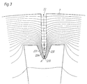
- Figure 3 shows the field plot for the leakage field of the machine at rated current.
- the bridge 23 shunts the leakage flux past that part of the slot opening 22 which faces the rotor conductor and effectively prevents the flux from penetrating into the rotor conductor and there causing additional losses.
- the material in that part of the rotor core which is located between the rotor slot and the rotor surface 7 is unsaturated, even at full current of the motor.
- the material in the bridge 23 achieves saturation even at a low motor current, whereupon the leakage flux will flow partly through the space 234 between the two branches of the bridge (B in Fig. 3) and partly through the main portion of the slot opening 22 (C in Fig. 3).
- the shape and the dimensions of the two branches of the bridge and of the space between the branches are so chosen that the material in the entire bridge 23 achieves magnetic saturation approximately Simultaneously at the above-mentioned low value of the load current of the motor.
- the width a of the bridge nearest its tip 233 is suitably made as small as possible. For reasons of manufacturing technique and for reasons of strength, however, this width cannot be reduced to below a certain value, for example 0.5 mm. A certain part of the leakage flux will therefore also traverse the tip of the bridge (region A in Figure 3).
- Figure 4 shows the leakage flux F of the rotor as a function of the load current I of the motor.
- the rated current of the motor is designated I 1/1.
- the flux component FA designates that part of the leakage flux which traverses the tip 233 of the bridge (region A). Since the bridge is dimensioned such that its material becomes magnetically saturated even at a low load current of the motor, the flux component FA increases rapidly to a saturation value and thereafter remains constant at an increasing load current I.
- the flux component which flows through the region B between the branches of the bridge is designated FB and grows linearly with the load current I.
- Figure 4 shows that flux component which is made up of the sum of the components FA and FB.
- the flux component flowing through the actual slot opening 22 is designated FC.
- the curve FA + FB + FC in Figure 4 shows the sum of the three flux components Just mentioned, i.e. the total leakage flux.
- the total leakage flux is a near linear function of the load current of the motor.
- a differential reactance is therefore obtained which is as high as possible at a motor load in the vicinity of the rated load of the motor. Since it is the differential leakage reactance that limits the harmonic currents, a very good limitation of these currents is obtained in the machine according to the invention, and hence a limitation of the additional losses of the machine.
- a motor according to the invention is especially well suited for operation of objects having a constant load torque, for example compressors.
- the motor described above is only an example of how a motor may be designed according to the invention.
- the invention can be applied with advantage to both small and large motors and to motors for both low and very high speeds.
- FIG. 5a shows a theoretically advantageous embodiment, in which both the outsides and the insides of the branches 231 and 232 are straight and converge at a point at the tip 233 of the bridge.
- this shape must be modified, and the embodiment of the bridge shown in Figures 1-3 constitutes a practically suitable good approximation of the embodiment shown in Figure 5a.
- Figures 5b and 5f show two other feasible embodiments, in which the space between the two branches of the bridge has a constant width.
- Figures 5c, 5d and 5f show alternative embodiments, in which the width of the bridge is constant along the length of the bridge. These embodiments are usable in practice and afford advantages compared with prior art machines, but compared with the embodiments according to Figures 1-3 and Figure 5a, a less effective shielding of the flux from the rotor conductor and an inferior linearity are obtained, i.e. a lower differential reactance at rated load.
- Figure 5d differs from Figure 5f in that the height of the bridge (in a radial direction) is larger in the bridge according to Figure 5f.
- Figure 5e shows a modification of Figure 5a in which the sides of the bridge branches do not consist of straight lines but are somewhat curved.
- the bridges shown in Figures 1-3, 5a, 5c, 5e are V-shaped, that is, they have two non-parallel branches 231, 232 meeting at a more or less rounded tip 233.
- the bridge shown in Figure 5f is U-shaped, that is, it has two essentially parallel branches 231, 232, connected by a central portion 233.
- the bridge shown in Figure 5b is V-shaped and has a U-shaped recess.
- the total width of the bridge (d + 2b in Fig. 2) must be adapted to the individual motor in such a way that it is made so large that an effective shunting of the leakage flux past the slot opening is obtained, however not so large that a leakage flux of a significant magnitude occurs between the branches of the bridge and the radially directed edges of the rotor slot.
- the bridge according to the invention forms part of the rotor sheet package.
- the bridge may consist of a separate part.
- the bridge may, for example, be mounted on the rotor rod, for example glued thereto, and be inserted together with the rod into the rotor slot.
Landscapes
- Engineering & Computer Science (AREA)
- Power Engineering (AREA)
- Induction Machinery (AREA)
- Iron Core Of Rotating Electric Machines (AREA)
- Control Of Multiple Motors (AREA)
- Control Of Ac Motors In General (AREA)
Abstract
Description
- The present invention relates to a squirrel-cage induction motor for frequency convertor operation comprising a rotor having a rotor core with a plurality of substantially axially extending rotor slots, in which rotor conductors are arranged, each rotor slot having a main portion in which a rotor conductor is arranged and a slot opening arranged between the main portion and that surface of the rotor which faces the air gap of the motor.
- It is known that an asynchronous motor can be supplied from a static frequency convertor, for example for achieving a high speed of the motor or for making possible control of the speed of the motor. However, in frequency convertor operation additional losses - harmonic losses - will arise because of harmonics in the motor current. By designing the motor so that its leakage reactance (short-circuit reactance) is high, a reduction of the harmonic currents, and hence of the additional losses, is obtained. However, an increase of the leakage reactance entails a reduction of the maximum torque of the motor and of its power factor, and it is therefore possible only to a limited extent to reduce the additional losses in this way.
- From Swedish published patent application with publication number 433 995 it is known that the additional losses in an asynchronous motor supplied by a frequency convertor may be reduced by providing each winding bar with an axially extending channel facing the slot opening. However, this solution has several drawbacks. It is not possible to use it in rotor windings of a cast design. It gives a relatively low value of the differential leakage reactance of the motor and hence still relatively high harmonic currents and additional losses. In the solution mentioned it is not possible to effectively prevent the field in the vicinity of the slot opening from penetrating into the rotor conductor and there generating additional losses. Further, in this known solution it is the eddy currents in the rotor conductor that reduce the field penetrating into the conductor, and the effect achieved is therefore inseparably connected with a certain degree of additional losses.
- The invention aims to provide a motor of the kind described in the introductory part of the description, which
- a) makes it possible to use both cast rotor windings and bar windings,
- b) exhibits considerably reduced additional losses, and
- c) gives improved cooling of the rotor winding.
- The above is achieved by providing the rotor core, according to the invention, with a magnetic bridge which is arranged to separate the slot opening from the main portion of the slot, the ends of the bridge adjoining the rest of the rotor core on either side of the slot opening, and the surface of the bridge, which faces the interior of the rotor conductor, having a shape which is curved towards the interior of the rotor conductor.
- As will be described more closely below, this provides a possibility of designing the rotor winding as a cast squirrel-cage winding, a considerable reduction of the additional losses of the motor and improved cooling of the rotor winding.
- According to a preferred embodiment of the invention, the bridge is provided with a recess, constituting an extension of the slot opening in the direction towards the interior of the rotor conductor. This results in an increase of the effective area exhibited by the slot opening for the leakage flux of the rotor conductor and hence an increase of the differential leakage reactance and a reduction of the harmonic currents and the additional losses.
- The above-mentioned recess is preferably made tapering from the slot opening in the direction of the rotor conductor and, in similar manner, the width of the bridge is made tapering from the ends of the bridge towards the part thereof located centrally and directed towards the interior of the rotor conductor. This results in a very effective shielding of the leakage flux from the rotor conductor and, in addition, as linear a variation as possible of the leakage reactance of the rotor with the load of the motor, which for a given maximum leakage reactance gives a differential leakage reactance as high as possible at the working point and hence a very effective reduction of harmonic currents and additional losses.
- The invention will be described in the following with reference to the accompanying Figures 1-5, wherein
- Figure 1 shows part of a section through the rotor in a machine according to the invention,
- Figure 2 shows in more detail the design of the rotor core at one of the slots in the rotor shown in Figure 1,
- Figure 3 shows the field plot for the leakage field at rated current of the machine according to Figures 1 and 2,
- Figure 4 shows the leakage flux as a function of the load current of the motor, and
- Figures 5a-5f show alternative embodiments of the bridge according to the invention.
- Figures 1-4 show an example of a squirrel-cage induction motor according to the invention and its function. Figure 1 shows part of a section through the rotor perpendicular to the axis of rotation of the rotor. The
rotor core 1 is, as usual, built up as a package of sheets, the plane of which lies in the plane of the paper, i.e. perpendicular to the axis of rotation of the motor. The rotor is provided with a cast squirrel cage winding, of which rotor conductors 2-6 are shown in Figure 1. The slots of the rotor are mutually identical, and in the following that slot in which the conductor 2 is arranged will be described. The slot has amain portion 21, into which conductor 2 is cast. Further, the slot has aslot opening 22 which is arranged, in a manner known per se, between themain portion 21 of the slot and thatsurface 7 of the rotor which faces the air gap and stator of the machine. A V-shaped bridge 23, which constitutes part of the rotor sheet section, adjoins the other parts of the rotor on either side of theslot opening 22 and has its tip directed towards the interior of the rotor conductor 2 (radially inwards towards the axis of rotation of the machine). Figure 2 shows in more detail the design of thebridge 23. It has twobranches tip 233. The branches form between them an air gap (recess) 234. The width e of the recess nearest theslot opening 22 is equal to the width d of theslot opening 22 and decreases in a radially inward direction to a low value nearest thetip 233 of the bridge. Thus, between thebranches tip 233 of the bridge. - The bridge 23 - as seen in the plane of the drawing - has two
ends rotor core 1 at both sides of the slot opening 22, and acentral part 233, situated between the two ends. Thecentral part 233 of the bridge is situated closer to the axis of the rotor than theends main portion 21 of the rotor slot - and thus facing the rotor conductor 2 - is therefore convex or curved radially inward, that is, towards the interior of themain slot portion 21 and thus towards the rotor conductor 2. - A motor according to the invention may have 28 motor conductors and otherwise the following data:
rated voltage 380 V
rated current 155 A
rated speed 9000 rpm
rated power 80 kW
rotor diameter 211 mm - Further, it may have the dimensions stated in Figure 2:
d = 1.7 mm
b = 1.8 mm
a = 0.5 mm
h = 4.0 mm
B = 11 mm - Figure 3 shows the field plot for the leakage field of the machine at rated current. The
bridge 23 shunts the leakage flux past that part of the slot opening 22 which faces the rotor conductor and effectively prevents the flux from penetrating into the rotor conductor and there causing additional losses. The material in that part of the rotor core which is located between the rotor slot and therotor surface 7 is unsaturated, even at full current of the motor. On the other hand, the material in thebridge 23 achieves saturation even at a low motor current, whereupon the leakage flux will flow partly through thespace 234 between the two branches of the bridge (B in Fig. 3) and partly through the main portion of the slot opening 22 (C in Fig. 3). The shape and the dimensions of the two branches of the bridge and of the space between the branches are so chosen that the material in theentire bridge 23 achieves magnetic saturation approximately Simultaneously at the above-mentioned low value of the load current of the motor. The width a of the bridge nearest itstip 233 is suitably made as small as possible. For reasons of manufacturing technique and for reasons of strength, however, this width cannot be reduced to below a certain value, for example 0.5 mm. A certain part of the leakage flux will therefore also traverse the tip of the bridge (region A in Figure 3). - Figure 4 shows the leakage flux F of the rotor as a function of the load current I of the motor. The rated current of the motor is designated I 1/1. The flux component FA designates that part of the leakage flux which traverses the
tip 233 of the bridge (region A). Since the bridge is dimensioned such that its material becomes magnetically saturated even at a low load current of the motor, the flux component FA increases rapidly to a saturation value and thereafter remains constant at an increasing load current I. The flux component which flows through the region B between the branches of the bridge is designated FB and grows linearly with the load current I. Figure 4 shows that flux component which is made up of the sum of the components FA and FB. The flux component flowing through theactual slot opening 22 is designated FC. The curve
- In a motor of the kind described here it is important that the
slot openings 22 are free from conductor material, since otherwise very high additional losses would be generated in the conductor material present at these openings. - The embodiment of a machine according to the invention as described above provides several important advantages compared with prior art motors for frequency convertor operation:
- a) The
bridge 23 effectively prevents the molten conductor material, in the manufacture of a squirrel cage by casting, from penetrating into the slot opening, causing additional losses there. - b) By the extra flux paths which are created through the tip of the bridge (A in Fig. 3) and through the region between the branches of the bridge (B in Fig. 3), an increase of the leakage reactance of the rotor, and hence a reduction of harmonic currents and additional losses, is obtained. The good linearity of the leakage flux as a function of the load which is obtainable in a machine according to the invention contributes to this, which gives a high differential reactance at the working point.
- c) The
bridge 23 shunts the leakage flux past the slot opening and therefore effectively shields the rotor conductor from the leakage flux. In this way, the eddy current losses in the conductor material, which otherwise occur at high frequencies, are effectively prevented, and the effective rotor resistance for the harmonics is greatly reduced. - d) Since the rotor conductor along the whole of its circumference, also at the slot opening, makes contact with the rotor sheets, a more efficient removal of loss heat from the rotor conductors is obtained than in prior art machines of a similar kind. This improved cooling is particularly advantageous in high-speed motors in which, in order to reduce the ventilation losses, the
slot openings 22 must be closed nearest the air gap so that the rotor is given a smooth surface and in which, consequently, no significant cooling via the slot opening may take place. - The motor described above is only an example of how a motor may be designed according to the invention. The invention can be applied with advantage to both small and large motors and to motors for both low and very high speeds.
- The embodiment of the
bridge 23 described above is also just an example and a plurality of other embodiments are feasible. Figures 5a-5f show a few examples of other feasible embodiments. Figure 5a shows a theoretically advantageous embodiment, in which both the outsides and the insides of thebranches tip 233 of the bridge. For reasons of manufacturing technique, however, this shape must be modified, and the embodiment of the bridge shown in Figures 1-3 constitutes a practically suitable good approximation of the embodiment shown in Figure 5a. - Figures 5b and 5f show two other feasible embodiments, in which the space between the two branches of the bridge has a constant width. Figures 5c, 5d and 5f show alternative embodiments, in which the width of the bridge is constant along the length of the bridge. These embodiments are usable in practice and afford advantages compared with prior art machines, but compared with the embodiments according to Figures 1-3 and Figure 5a, a less effective shielding of the flux from the rotor conductor and an inferior linearity are obtained, i.e. a lower differential reactance at rated load. Figure 5d differs from Figure 5f in that the height of the bridge (in a radial direction) is larger in the bridge according to Figure 5f. This provides an enlargement of the additional flux path which is created between the branches of the bridge and thus, as mentioned above, a higher leakage reactance. It has been found that in order to obtain the advantages of the invention to a substantial extent, the height of the bridge (h in Fig. 2) should exceed the width of the slot opening (d in Fig. 2).
- Figure 5e shows a modification of Figure 5a in which the sides of the bridge branches do not consist of straight lines but are somewhat curved.
- The bridges shown in Figures 1-3, 5a, 5c, 5e are V-shaped, that is, they have two
non-parallel branches rounded tip 233. The bridge shown in Figure 5f is U-shaped, that is, it has two essentiallyparallel branches central portion 233. The bridge shown in Figure 5b is V-shaped and has a U-shaped recess. - The total width of the bridge (d + 2b in Fig. 2) must be adapted to the individual motor in such a way that it is made so large that an effective shunting of the leakage flux past the slot opening is obtained, however not so large that a leakage flux of a significant magnitude occurs between the branches of the bridge and the radially directed edges of the rotor slot.
- In the embodiments described above, the bridge according to the invention forms part of the rotor sheet package. Alternatively, the bridge may consist of a separate part. In a bar-based rotor winding the bridge may, for example, be mounted on the rotor rod, for example glued thereto, and be inserted together with the rod into the rotor slot.
Claims (9)
- A squirrel-cage induction motor for frequency convertor operation with a rotor which has a rotor core (1) with a plurality of substantially axially extending rotor slots (e.g. 21, 22) in which rotor conductors (2-6) are arranged, each rotor slot having a main portion (21) in which a rotor conductor (2) is arranged and a slot opening (22) arranged between the main portion (21) and that surface (7) of the rotor facing the air gap of the motor, characterized in that a magnetic bridge (23) is arranged to separate the slot opening (22) from the main portion (21) of the slot, that the ends (235, 236) of the bridge adjoin the rest of the rotor core on either side of the slot opening, and that that surface of the bridge, which faces the interior of the rotor conductor (2), has a shape which is curved towards the interior of the rotor conductor.
- A squirrel-cage induction motor according to claim 1, characterized in that the width (a, b) of the bridge (23) is smaller (a) at the central part (233) of the bridge than at the ends (b) of the bridge.
- A squirrel-cage induction motor according to claim 2, characterized in that the width of the bridge decreases continuously from the ends towards the central part (233).
- A squirrel-cage induction motor according to any of the preceding claims, characterized in that the ratio between the height (h) of the bridge (23) and the width (d) of the slot opening (22) is greater than 1.
- A squirrel-cage induction motor according to any of the preceding claims, characterized in that the bridge (23) is provided with a recess (234) which forms an extension of the slot opening (22) towards the interior of the rotor conductor (2).
- A squirrel-cage induction motor according to claim 5, characterized in that the width (e) of the recess (234) decreases from the slot opening (22) in a direction towards the rotor conductor.
- A squirrel-cage induction motor according to claim 6, characterized in that the width (e) of the recess decreases continuously from the slot opening in a direction towards the rotor conductor.
- A squirrel-cage induction motor according to any of claims 5-7, characterized in that the bridge (23) is U- or V-shaped with two branches (231, 232) arranged on each side of the centre (233) of the bridge, said branches forming between them said recess (234).
- A squirrel-cage induction motor according to any of the preceding claims, characterized in that the slot opening (22) is free from rotor conductors.
Applications Claiming Priority (2)
| Application Number | Priority Date | Filing Date | Title |
|---|---|---|---|
| SE8803665A SE462310B (en) | 1988-10-14 | 1988-10-14 | SHORT-ASYNCHRONOUS MOTOR FOR FREQUENCY DRIVE DRIVE |
| SE8803665 | 1988-10-14 |
Publications (2)
| Publication Number | Publication Date |
|---|---|
| EP0438442A1 EP0438442A1 (en) | 1991-07-31 |
| EP0438442B1 true EP0438442B1 (en) | 1993-12-29 |
Family
ID=20373630
Family Applications (1)
| Application Number | Title | Priority Date | Filing Date |
|---|---|---|---|
| EP89911117A Expired - Lifetime EP0438442B1 (en) | 1988-10-14 | 1989-10-02 | Squirrel-cage induction motor for frequency convertor operation |
Country Status (8)
| Country | Link |
|---|---|
| US (1) | US5155404A (en) |
| EP (1) | EP0438442B1 (en) |
| AT (1) | ATE99467T1 (en) |
| AU (1) | AU617544B2 (en) |
| DE (1) | DE68911929T2 (en) |
| FI (1) | FI108094B (en) |
| SE (1) | SE462310B (en) |
| WO (1) | WO1990004281A1 (en) |
Cited By (3)
| Publication number | Priority date | Publication date | Assignee | Title |
|---|---|---|---|---|
| US8550196B2 (en) | 2009-08-31 | 2013-10-08 | New Core, Inc. | Multiple induction electric motor and vehicle |
| EP2999100A1 (en) | 2014-09-18 | 2016-03-23 | Bombardier Transportation GmbH | A method for producing a squirrel-cage rotor and a rotor produced thereby |
| US9806587B2 (en) | 2013-08-26 | 2017-10-31 | Robert Ross | System and method for stator construction of an electric motor |
Families Citing this family (22)
| Publication number | Priority date | Publication date | Assignee | Title |
|---|---|---|---|---|
| SE468265B (en) * | 1991-04-08 | 1992-11-30 | Asea Brown Boveri | ROTOR TO SHORT-CIRCUIT DRIVE MOTOR |
| US5640599A (en) * | 1991-12-30 | 1997-06-17 | Apple Computer, Inc. | Interconnect system initiating data transfer over launch bus at source's clock speed and transfering data over data path at receiver's clock speed |
| GB2289992B (en) * | 1994-05-24 | 1998-05-20 | Gec Alsthom Ltd | Improvements in or relating to cooling arrangements in rotating electrical machines |
| US5808391A (en) * | 1996-05-02 | 1998-09-15 | Chrysler Corporation | Rotor squirrel cage construction |
| US6777847B1 (en) * | 1998-06-26 | 2004-08-17 | General Electric Company | Rotor core utilizing laminations having slots with dual direction skew portions |
| HUP0102029A3 (en) * | 1998-06-26 | 2002-10-28 | Gen Electric | Rotor core, rotor and ac electric motor utilizing a stepped skew |
| US6058596A (en) * | 1998-08-03 | 2000-05-09 | General Electric Company | Method of making an induction motor rotor |
| DE10345637A1 (en) * | 2003-09-29 | 2005-05-25 | Siemens Ag | Squirrel-cage |
| DE102006033792A1 (en) * | 2006-07-19 | 2008-02-07 | Rolf Meyer | Frequency converter fed three-phase asynchronous motor |
| CN201219227Y (en) * | 2008-07-30 | 2009-04-08 | 无锡东元电机有限公司 | Permanent magnet synchronous machine rotor |
| CN201204529Y (en) * | 2008-08-28 | 2009-03-04 | 无锡东元电机有限公司 | Permanent magnet synchronous motor |
| JPWO2010047173A1 (en) * | 2008-10-23 | 2012-03-22 | 株式会社日立産機システム | Cage type induction motor and cage type induction motor drive system |
| CN201294443Y (en) * | 2008-12-01 | 2009-08-19 | 东元总合科技(杭州)有限公司 | Permanent magnet self-startup synchronous motor rotor |
| DE102009042452A1 (en) | 2009-09-23 | 2011-03-31 | Elektromotorenwerk Grünhain GmbH & Co. KG | Cage rotor for electric machines, has rotor made of pierced motor sheet and multiple grooves with arbitrary geometric figure, where end area of grooves pointing to outer circumference of rotor is formed with rare earth material |
| JP5557685B2 (en) * | 2010-10-14 | 2014-07-23 | 株式会社日立製作所 | Rotating electric machine |
| US10396615B2 (en) | 2013-02-28 | 2019-08-27 | General Electric Company | Electric machine stator lamination with dual phase magnetic material |
| DE102013209186B4 (en) | 2013-05-17 | 2026-03-05 | Robert Bosch Gmbh | Component of an electric machine and methods for its manufacture |
| DE102016124830B4 (en) * | 2016-12-19 | 2025-06-05 | Fraunhofer-Gesellschaft zur Förderung der angewandten Forschung e.V. | Sheet metal for forming a laminated core for a rotor of an electrical machine |
| DE102017200980A1 (en) * | 2017-01-23 | 2018-07-26 | Audi Ag | Short-circuit rotor, asynchronous motor and motor vehicle |
| US11661646B2 (en) | 2021-04-21 | 2023-05-30 | General Electric Comapny | Dual phase magnetic material component and method of its formation |
| US11926880B2 (en) | 2021-04-21 | 2024-03-12 | General Electric Company | Fabrication method for a component having magnetic and non-magnetic dual phases |
| DE102024203171A1 (en) * | 2024-04-08 | 2025-10-09 | Volkswagen Aktiengesellschaft | Sheet for forming a laminated core for a rotor of an electrical machine and electrical machine |
Family Cites Families (14)
| Publication number | Priority date | Publication date | Assignee | Title |
|---|---|---|---|---|
| DE505779C (en) * | 1930-08-27 | Aeg | Kaefiglaeufer for induction motors with a working winding and a starting winding and alternating deep and low grooves | |
| DE533919C (en) * | 1931-09-19 | Sachsenwerk Licht & Kraft Ag | Double cage anchor with open or half-open slots in the run-up cage winding | |
| DE624366C (en) * | 1936-01-18 | Siemens Schuckertwerke Akt Ges | Double cage runner | |
| DE460124C (en) * | 1922-10-10 | 1928-05-22 | Bbc Brown Boveri & Cie | Laminated magnetic wedge to close the winding grooves of electrical machines |
| US2067605A (en) * | 1935-03-28 | 1937-01-12 | Wagner Electric Corp | Laminae construction for dynamoelectric machines |
| US2794138A (en) * | 1954-05-27 | 1957-05-28 | Gen Electric | Closed slot rotor punching |
| US2944171A (en) * | 1957-01-04 | 1960-07-05 | Gen Electric | Intermediate ring squirrel cage rotor |
| US4139790A (en) * | 1977-08-31 | 1979-02-13 | Reliance Electric Company | Direct axis aiding permanent magnets for a laminated synchronous motor rotor |
| US4246505A (en) * | 1979-03-19 | 1981-01-20 | Hitachi, Ltd. | Rotor with salient poles and shield plates between the poles |
| US4499660A (en) * | 1979-11-16 | 1985-02-19 | General Electric Company | Method of making a laminated rotor for a dynamoelectric machine |
| US4358696A (en) * | 1981-08-19 | 1982-11-09 | Siemens-Allis, Inc. | Permanent magnet synchronous motor rotor |
| JPS6028758A (en) * | 1983-07-27 | 1985-02-13 | Hitachi Ltd | Rotary electric machine with permanent magnet |
| US4568846A (en) * | 1983-10-28 | 1986-02-04 | Welco Industries | Permanent magnet laminated rotor with conductor bars |
| US4782260A (en) * | 1987-02-27 | 1988-11-01 | General Electric Company | Closed slot rotor construction |
-
1988
- 1988-10-14 SE SE8803665A patent/SE462310B/en not_active IP Right Cessation
-
1989
- 1989-10-02 EP EP89911117A patent/EP0438442B1/en not_active Expired - Lifetime
- 1989-10-02 AU AU43345/89A patent/AU617544B2/en not_active Expired
- 1989-10-02 WO PCT/SE1989/000536 patent/WO1990004281A1/en not_active Ceased
- 1989-10-02 AT AT89911117T patent/ATE99467T1/en not_active IP Right Cessation
- 1989-10-02 DE DE68911929T patent/DE68911929T2/en not_active Expired - Lifetime
- 1989-10-02 US US07/671,847 patent/US5155404A/en not_active Expired - Lifetime
-
1991
- 1991-04-12 FI FI911802A patent/FI108094B/en active
Cited By (4)
| Publication number | Priority date | Publication date | Assignee | Title |
|---|---|---|---|---|
| US8550196B2 (en) | 2009-08-31 | 2013-10-08 | New Core, Inc. | Multiple induction electric motor and vehicle |
| US8950529B2 (en) | 2009-08-31 | 2015-02-10 | Multiple Electric Systems, L.L.C. | Multiple induction electric motor and vehicle |
| US9806587B2 (en) | 2013-08-26 | 2017-10-31 | Robert Ross | System and method for stator construction of an electric motor |
| EP2999100A1 (en) | 2014-09-18 | 2016-03-23 | Bombardier Transportation GmbH | A method for producing a squirrel-cage rotor and a rotor produced thereby |
Also Published As
| Publication number | Publication date |
|---|---|
| SE8803665D0 (en) | 1988-10-14 |
| FI911802A0 (en) | 1991-04-12 |
| AU617544B2 (en) | 1991-11-28 |
| ATE99467T1 (en) | 1994-01-15 |
| EP0438442A1 (en) | 1991-07-31 |
| FI108094B (en) | 2001-11-15 |
| DE68911929T2 (en) | 1994-07-14 |
| DE68911929D1 (en) | 1994-02-10 |
| SE462310B (en) | 1990-05-28 |
| WO1990004281A1 (en) | 1990-04-19 |
| AU4334589A (en) | 1990-05-01 |
| US5155404A (en) | 1992-10-13 |
Similar Documents
| Publication | Publication Date | Title |
|---|---|---|
| EP0438442B1 (en) | Squirrel-cage induction motor for frequency convertor operation | |
| US4385251A (en) | Flux shield for an inductor-alternator machine | |
| KR100807853B1 (en) | A dynamoelectric machine | |
| EP1050949A1 (en) | Motor | |
| US20030011267A1 (en) | Harmonic-frequency synchronous machine with flux concentration | |
| EP0620952A1 (en) | LIGHTWEIGHT ELECTRIC MOTOR LIGHTWEIGHT DEVICE. | |
| US4409506A (en) | Induction motor | |
| CN111864940A (en) | Core structure, rotor assembly, motor and compressor | |
| US20080054733A1 (en) | Slotless Ac Induction Motor | |
| EP1444765B1 (en) | Electric motor | |
| US4435664A (en) | Magnetic interpole apparatus for improving commutation characteristics of a dynamoelectric machine | |
| EP0549241A2 (en) | Electrical machines | |
| WO1990004280A1 (en) | Squirrel-cage induction motor for frequency convertor operation | |
| US3328616A (en) | Dynamoelectric induction machines | |
| US11770035B2 (en) | Laminated core for an electric machine | |
| EP0541680B1 (en) | Magnetic bearings | |
| CA1115320A (en) | Damper winding in a salient-pole type synchronous machine | |
| JP2743122B2 (en) | Superconducting rotating electric machine stator | |
| JP2000116040A (en) | Salient pole rotor of rotating electric machine | |
| SU1690084A1 (en) | Stator of electrical machine of alternating current | |
| RU2107375C1 (en) | Commutator machine stator | |
| KR850002268Y1 (en) | Induction motor | |
| JPS5826555A (en) | Stator for induction motor | |
| JPS596756A (en) | induction motor | |
| JP2002252948A (en) | Salient pole type rotor of rotating electric machine |
Legal Events
| Date | Code | Title | Description |
|---|---|---|---|
| PUAI | Public reference made under article 153(3) epc to a published international application that has entered the european phase |
Free format text: ORIGINAL CODE: 0009012 |
|
| 17P | Request for examination filed |
Effective date: 19910409 |
|
| AK | Designated contracting states |
Kind code of ref document: A1 Designated state(s): AT BE CH DE FR GB IT LI LU NL SE |
|
| 17Q | First examination report despatched |
Effective date: 19930203 |
|
| GRAA | (expected) grant |
Free format text: ORIGINAL CODE: 0009210 |
|
| AK | Designated contracting states |
Kind code of ref document: B1 Designated state(s): AT BE CH DE FR GB IT LI LU NL SE |
|
| PG25 | Lapsed in a contracting state [announced via postgrant information from national office to epo] |
Ref country code: SE Effective date: 19931229 |
|
| REF | Corresponds to: |
Ref document number: 99467 Country of ref document: AT Date of ref document: 19940115 Kind code of ref document: T |
|
| REF | Corresponds to: |
Ref document number: 68911929 Country of ref document: DE Date of ref document: 19940210 |
|
| ITF | It: translation for a ep patent filed | ||
| ET | Fr: translation filed | ||
| PLBE | No opposition filed within time limit |
Free format text: ORIGINAL CODE: 0009261 |
|
| STAA | Information on the status of an ep patent application or granted ep patent |
Free format text: STATUS: NO OPPOSITION FILED WITHIN TIME LIMIT |
|
| 26N | No opposition filed | ||
| REG | Reference to a national code |
Ref country code: GB Ref legal event code: IF02 |
|
| PGFP | Annual fee paid to national office [announced via postgrant information from national office to epo] |
Ref country code: CH Payment date: 20070927 Year of fee payment: 19 |
|
| PGFP | Annual fee paid to national office [announced via postgrant information from national office to epo] |
Ref country code: NL Payment date: 20081005 Year of fee payment: 20 |
|
| PGFP | Annual fee paid to national office [announced via postgrant information from national office to epo] |
Ref country code: LU Payment date: 20081003 Year of fee payment: 20 Ref country code: DE Payment date: 20081014 Year of fee payment: 20 |
|
| PGFP | Annual fee paid to national office [announced via postgrant information from national office to epo] |
Ref country code: AT Payment date: 20081013 Year of fee payment: 20 |
|
| PGFP | Annual fee paid to national office [announced via postgrant information from national office to epo] |
Ref country code: IT Payment date: 20081028 Year of fee payment: 20 Ref country code: BE Payment date: 20081009 Year of fee payment: 20 |
|
| PGFP | Annual fee paid to national office [announced via postgrant information from national office to epo] |
Ref country code: FR Payment date: 20081014 Year of fee payment: 20 |
|
| REG | Reference to a national code |
Ref country code: CH Ref legal event code: PL |
|
| PGFP | Annual fee paid to national office [announced via postgrant information from national office to epo] |
Ref country code: GB Payment date: 20081001 Year of fee payment: 20 |
|
| REG | Reference to a national code |
Ref country code: GB Ref legal event code: PE20 Expiry date: 20091001 |
|
| PG25 | Lapsed in a contracting state [announced via postgrant information from national office to epo] |
Ref country code: LI Free format text: LAPSE BECAUSE OF NON-PAYMENT OF DUE FEES Effective date: 20081031 Ref country code: CH Free format text: LAPSE BECAUSE OF NON-PAYMENT OF DUE FEES Effective date: 20081031 |
|
| BE20 | Be: patent expired |
Owner name: *ASEA BROWN BOVERI A.B. Effective date: 20091002 |
|
| PG25 | Lapsed in a contracting state [announced via postgrant information from national office to epo] |
Ref country code: GB Free format text: LAPSE BECAUSE OF EXPIRATION OF PROTECTION Effective date: 20091001 |
|
| NLV7 | Nl: ceased due to reaching the maximum lifetime of a patent | ||
| PG25 | Lapsed in a contracting state [announced via postgrant information from national office to epo] |
Ref country code: NL Free format text: LAPSE BECAUSE OF EXPIRATION OF PROTECTION Effective date: 20091002 |