EP0437485B1 - A robot end effector - Google Patents
A robot end effector Download PDFInfo
- Publication number
- EP0437485B1 EP0437485B1 EP89911275A EP89911275A EP0437485B1 EP 0437485 B1 EP0437485 B1 EP 0437485B1 EP 89911275 A EP89911275 A EP 89911275A EP 89911275 A EP89911275 A EP 89911275A EP 0437485 B1 EP0437485 B1 EP 0437485B1
- Authority
- EP
- European Patent Office
- Prior art keywords
- end effector
- robot end
- intermediate layer
- effector according
- strip material
- Prior art date
- Legal status (The legal status is an assumption and is not a legal conclusion. Google has not performed a legal analysis and makes no representation as to the accuracy of the status listed.)
- Expired - Lifetime
Links
- 239000012636 effector Substances 0.000 title claims abstract description 68
- 239000000463 material Substances 0.000 claims abstract description 25
- 238000010276 construction Methods 0.000 claims description 8
- 239000006261 foam material Substances 0.000 claims description 5
- 229920005830 Polyurethane Foam Polymers 0.000 claims description 4
- 239000002131 composite material Substances 0.000 claims description 4
- 239000011496 polyurethane foam Substances 0.000 claims description 4
- 229920001971 elastomer Polymers 0.000 claims description 3
- 239000002245 particle Substances 0.000 claims description 2
- 239000004020 conductor Substances 0.000 claims 1
- 239000011800 void material Substances 0.000 claims 1
- 239000004744 fabric Substances 0.000 abstract description 5
- 238000009958 sewing Methods 0.000 description 6
- XAGFODPZIPBFFR-UHFFFAOYSA-N aluminium Chemical compound [Al] XAGFODPZIPBFFR-UHFFFAOYSA-N 0.000 description 4
- 229910052782 aluminium Inorganic materials 0.000 description 4
- 230000002093 peripheral effect Effects 0.000 description 4
- 238000010008 shearing Methods 0.000 description 3
- 238000013461 design Methods 0.000 description 2
- 238000012856 packing Methods 0.000 description 2
- 238000013459 approach Methods 0.000 description 1
- 230000001413 cellular effect Effects 0.000 description 1
- 230000008878 coupling Effects 0.000 description 1
- 238000010168 coupling process Methods 0.000 description 1
- 238000005859 coupling reaction Methods 0.000 description 1
- 230000005611 electricity Effects 0.000 description 1
- 239000002783 friction material Substances 0.000 description 1
- 238000000034 method Methods 0.000 description 1
- 238000012545 processing Methods 0.000 description 1
- 239000007787 solid Substances 0.000 description 1
- 230000003068 static effect Effects 0.000 description 1
Images



Classifications
-
- B—PERFORMING OPERATIONS; TRANSPORTING
- B25—HAND TOOLS; PORTABLE POWER-DRIVEN TOOLS; MANIPULATORS
- B25J—MANIPULATORS; CHAMBERS PROVIDED WITH MANIPULATION DEVICES
- B25J15/00—Gripping heads and other end effectors
- B25J15/0019—End effectors other than grippers
-
- A—HUMAN NECESSITIES
- A41—WEARING APPAREL
- A41H—APPLIANCES OR METHODS FOR MAKING CLOTHES, e.g. FOR DRESS-MAKING OR FOR TAILORING, NOT OTHERWISE PROVIDED FOR
- A41H43/00—Other methods, machines or appliances
- A41H43/02—Handling garment parts or blanks, e.g. feeding, piling, separating or reversing
-
- D—TEXTILES; PAPER
- D05—SEWING; EMBROIDERING; TUFTING
- D05B—SEWING
- D05B33/00—Devices incorporated in sewing machines for supplying or removing the work
- D05B33/02—Devices incorporated in sewing machines for supplying or removing the work and connected, for synchronous operation, with the work-feeding devices of the sewing machine
-
- Y—GENERAL TAGGING OF NEW TECHNOLOGICAL DEVELOPMENTS; GENERAL TAGGING OF CROSS-SECTIONAL TECHNOLOGIES SPANNING OVER SEVERAL SECTIONS OF THE IPC; TECHNICAL SUBJECTS COVERED BY FORMER USPC CROSS-REFERENCE ART COLLECTIONS [XRACs] AND DIGESTS
- Y10—TECHNICAL SUBJECTS COVERED BY FORMER USPC
- Y10S—TECHNICAL SUBJECTS COVERED BY FORMER USPC CROSS-REFERENCE ART COLLECTIONS [XRACs] AND DIGESTS
- Y10S294/00—Handling: hand and hoist-line implements
- Y10S294/902—Gripping element
Definitions
- This invention relates to a robot end effector for pressing flexible workpieces, e.g. of fabric, onto and moving such workpieces over, a flat working surface.
- a known robot end effector is shown in WO 86/03948 and comprises a sandwich construction consisting of a backing sheet, a facing sheet for gripping the workpiece and a resilient intermediate layer for accommodating irregularities, such as seams or unequal multi-plies of fabric parts in subassemblies and local imperfections in the working surface.
- the backing sheet is U-shaped and the resilient intermediate layer and facing sheet are similarly shaped.
- the thickness of the intermediate layer is less than the width of the facing sheet which has a relatively large surface area.
- a sandwich construction end effector may be considered desirable for a sandwich construction end effector to have its backing sheet, facing sheet and intermediate layer all of the same size as a workpiece to be manoeuvred.
- this may result in the end effector being too bulky and having too high an inertia for effective, speedy manoeuvering.
- such a "solid" construction will result in air disturbance as an end effector is moved down on to a workpiece which will cause the latter to be displaced prior to contact between the effector and workpiece if the speed of movement of the end effector is not to be reduced to a slow approach.
- the weight of an end effector can be reduced by only contacting a workpiece around its periphery. This is achieved by employing peripheral strips of facing sheet.
- the form of the resilient intermediate layer is important. Ideally it should be easily compressed, e.g. made of a soft foam material. However such easily compressed material tends to undergo shearing movement as the end effector moves a workpiece over a work surface. To some extent this tendency of the intermediate layer to undergo shearing movement can be counteracted by increasing the width of the intermediate layer.
- Such WO 86/03948 in which the width of each strip of intermediate layer is considerably greater than its thickness. However this increased width of the strip-form intermediate layer increases the bulk of the end effector.
- the present invention seeks to provide an improved form of robot end effector having a sandwich construction.
- the width of the facing strip material is no greater than the thickness of the intermediate layer.
- the resilient intermediate layer requires a force of from 80 - 120 kg/m2, to compress it 1mm.
- the intermediate layer is a foam material, e.g. a polyurethane foam such as the marketed by Dunlopillo under the trade name "DHR 264 Dunloflex" - i.e. a high resilient grade polyurethane foam.
- the resilient intermediate layer has a thickness of from 20mm to 30mm, e.g. 25mm.
- the facing strip material has a width of less than 20mm, e.g. 15mm.
- the width of the intermediate layer where it is adjoined to the backing plate is greater than the width of the intermediate layer where it is adjoined to the facing strip material.
- the intermediate layer has a cross-section such that its inwardly facing side is at an angle, e.g. 45°, to the backing plate. If the end effector is provided with infer lengths of strip material (i.e. lengths disposed inwardly of the peripheral lengths) or outer lengths of strip material (i.e.
- the intermediate layer may have a cross-section of trapezoidal form, the two faces being disposed at equal angles, e.g. 45°, to the backing plate.
- the end effector is provides with a plurality of window-like apertures.
- the rigid packing plate comprises a lightweight composite panel such as an aluminum honeycomb structure sandwiched between facing sheets, e.g. of aluminum.
- a lightweight composite panel such as an aluminum honeycomb structure sandwiched between facing sheets, e.g. of aluminum.
- An example of such material is 0.5 inch (12.5mm) thick "Aerolam”.
- the backing plate material should be chosen for its rigidity and lightness.
- the facing sheet conveniently comprises an electrically conductive sheet, e.g. electrically conductive rubber sheet, typically having a thickness of approximately 1mm.
- weights are provided around the periphery of the end effector.
- Figure 1 shows one embodiment of a robot end effector 1 according to the invention attached to the end of a robot arm 2.
- the robot arm 2 can be rotated and moved in x, y, z and ⁇ directions.
- the end effector 1 comprises a rigid backing member 3, facing strip material 4 for contacting a workpiece to slide it across a horizontal work surface and a resilient intermediate layer 5.
- the member 3 has window-like openings 6 formed therein to enable escape of air as the end effector 1 is lowered onto a workpiece supported on a work surface.
- the width w of the strip material 4 is less than the thickness t of the intermediate layer 5.
- FIGS. 2 and 3 show the construction of another embodiment of robot end effector 10 in greater detail.
- the end effector 10 is intended for handling or gripping three different sizes of waist slip fabric having different waist perimeters but the same depth or length.
- the end effector 10 comprises a lightweight, rigid packing plate 11, a resilient intermediate layer 12 and a facing sheet 13 of strip like form bonded together to provide a sandwich construction.
- the backing plate 11 is typically 0.5 inch (12.5mm) thick and of composite form comprising a cellular, e.g. honeycomb, structure 14 sandwiched between facing sheets 15 and 16.
- a suitable material for the backing plate 11 is sold under the trade name "Aerolam" and consists of an aluminum honeycomb structure sandwiched between aluminum facing sheets.
- the resilient intermediate layer 12 suitably comprises a high resilient grade polyurethane foam typically having a thickness of from 20mm to 30mm, e.g. 25mm.
- a suitable foam material is marketed by Dunlopillo under the trade name "DHR 264 Dunloflex".
- the intermediate layer 12 has a trapezoidal cross-section with its inwardly facing surface angled at an inclined angle (e.g. 45°) to the backing plate 11. The purpose of this angling is to increase the resistance of the layer 12 to withstand a shearing movement during traverse of the end effector 10 across a work surface.
- the facing sheet 13 is conveniently an electrically conductive flexible sheet of friction material, e.g. a rubber sheet containing electrically conductive particles.
- the sheet 13 typically has a thickness of 1mm and each strip has a width (w) no more than 20mm, e.g. 15mm. Thus the width of each strip of the sheet 13 is no greater than the thickness (t) of the intermediate layer 12.
- the backing plate 11 has a plurality of window-like openings 18 formed therein to allow escape of air as the end effector 10 is lowered towards a workpiece 64 supported on a flat working surface 74.
- a mounting hole 19 is also formed in the plate 11 to enable the end effector 10 to be secured to the end of a robot arm (not shown) with the aid of bolts (not shown) entered into holes 20.
- the intermediate layer 12 and facing sheet 13 are arranged stripwise around the entire periphery of the backing plate 11 along top and bottom regions 21 and 22, respectively, and along side regions 23 and 24. Two further strips are spaced inwardly of the side regions 23 and 24 along regions 25 and 26, respectively.
- the regions 25 and 26 are used for manoeuvering a "small" size waist slip workpiece
- the regions 23 and 24 are used for manoeuvering a "large” size waist slip workpiece
- regions 23 and 26 or regions 24 and 25) are used for manoeuvering a "medium" size waist slip.
- the end effector 10 has a weight of 2.2kg and the total surface area of the facing sheet 13 is 64200 mm2.
- the extra load on the end effector 10 due to the robot coupling is 0.2 kg.
- an extra load of 2.25 kg requires to be applied to the end effector 10.
- this loading could be applied to the end effector by means of the robot arm.
- This centrally applied loading would tend to bend the entire end effector.
- the preferred method of loading the end effector 10 is therefore to apply weights 28 around the entire periphery of the upper surface of the backing plate 11. With the weights 28 added, the load/unit area of the facing sheet 13 is 72.4 kg/m2.
- FIG. 4, 5 and 6 Other designs of robot end effectors 30, 40 and 50 for differently shaped workpieces are shown in Figures 4, 5 and 6, respectively.
- the end effectors 30, 40 and 50 are basically similar in construction to the end effector 10 and where appropriate similar parts have been identified by similar reference numerals.
- window-like apertures are not shown and, in the end effector 50, window-like apertures and a mounting aperture are not shown. In practice, however, such apertures would be provided.
- the main additional features of the end effectors 30 and 50 are the strips 31 - 38 in end effector 30 and the strips 51 and 52 in the end effector 50. These strips enable different sizes of workpiece to be gripped. For example, with end effector 30, the strips 31 - 38 would be employed to grip a workpiece at spaced locations along side edges of the workpiece.
- Figures 7 and 8 show an attachment device 60 which may be attached to an end effector 61.
- the device 60 comprises a gripper pad 62 for gripping scalloped lace 63 to be sewn to a fabric piece 64, the stitch line being indicated by reference numeral 65.
- the pad 62 is mounted at one end of a horizontal arm 66 connected to a vertical shaft 67 journalled for sliding and pivoting movement in a journal 68 attached to the end effector 61.
- the top of the shaft 67 is connected to a further horizontal arm 69 which, in the position shown in Figure 7, rests in a slot 70 forming part of a cam surface 71 of a cam member 72.
- a spring 73 urges the arm 69 into the full line position shown in Figure 7.
- an upwardly sloping part in front of the sewing head of a sewing machine moves relatively to the attachment device 60 along the stitch line 65 and engages beneath the arm 66.
- the sloping part thereof lifts the arm 66 so that the arm 69 is moved out of the slot 70 and the pad 62 is raised clear of the lace 63.
- the sewing machine part pivots the arm 66 about the axis of the shaft 67 so that the pad 62 is swung clear of the stitch line 65 and the arm 69 is moved along the cam surface 71.
Landscapes
- Engineering & Computer Science (AREA)
- Textile Engineering (AREA)
- Robotics (AREA)
- Mechanical Engineering (AREA)
- Manipulator (AREA)
- Sewing Machines And Sewing (AREA)
Abstract
Description
- This invention relates to a robot end effector for pressing flexible workpieces, e.g. of fabric, onto and moving such workpieces over, a flat working surface.
- A known robot end effector is shown in WO 86/03948 and comprises a sandwich construction consisting of a backing sheet, a facing sheet for gripping the workpiece and a resilient intermediate layer for accommodating irregularities, such as seams or unequal multi-plies of fabric parts in subassemblies and local imperfections in the working surface. The backing sheet is U-shaped and the resilient intermediate layer and facing sheet are similarly shaped. In addition the thickness of the intermediate layer is less than the width of the facing sheet which has a relatively large surface area. Although this known end effector performs adequately for its predetermined task, i.e. gripping a workpiece during an unfolding operation and moving the workpiece along a defined path, its relative bulk renders it unsuitable for performing movements at the highest speeds required for modern processing.
- It may be considered desirable for a sandwich construction end effector to have its backing sheet, facing sheet and intermediate layer all of the same size as a workpiece to be manoeuvred. However, this may result in the end effector being too bulky and having too high an inertia for effective, speedy manoeuvering. Furthermore, such a "solid" construction will result in air disturbance as an end effector is moved down on to a workpiece which will cause the latter to be displaced prior to contact between the effector and workpiece if the speed of movement of the end effector is not to be reduced to a slow approach.
- The weight of an end effector can be reduced by only contacting a workpiece around its periphery. This is achieved by employing peripheral strips of facing sheet. When employing only strips of facing sheet the form of the resilient intermediate layer is important. Ideally it should be easily compressed, e.g. made of a soft foam material. However such easily compressed material tends to undergo shearing movement as the end effector moves a workpiece over a work surface. To some extent this tendency of the intermediate layer to undergo shearing movement can be counteracted by increasing the width of the intermediate layer. Such a solution is shown in WO 86/03948 in which the width of each strip of intermediate layer is considerably greater than its thickness. However this increased width of the strip-form intermediate layer increases the bulk of the end effector.
- The present invention seeks to provide an improved form of robot end effector having a sandwich construction.
- According to the present invention there is provided a robot end effector as claimed in the ensuing claim 1.
- Preferably, the width of the facing strip material is no greater than the thickness of the intermediate layer.
- Conveniently the resilient intermediate layer requires a force of from 80 - 120 kg/m², to compress it 1mm. Typically the intermediate layer is a foam material, e.g. a polyurethane foam such as the marketed by Dunlopillo under the trade name "DHR 264 Dunloflex" - i.e. a high resilient grade polyurethane foam.
- Typically the resilient intermediate layer has a thickness of from 20mm to 30mm, e.g. 25mm. Typically the facing strip material has a width of less than 20mm, e.g. 15mm.
- Suitably the width of the intermediate layer where it is adjoined to the backing plate is greater than the width of the intermediate layer where it is adjoined to the facing strip material. Conveniently, for the peripheral lengths of facing strip material, the intermediate layer has a cross-section such that its inwardly facing side is at an angle, e.g. 45°, to the backing plate. If the end effector is provided with infer lengths of strip material (i.e. lengths disposed inwardly of the peripheral lengths) or outer lengths of strip material (i.e. lengths disposed outwardly of peripheral lengths positioned slightly inwardly of a workpiece periphery), the intermediate layer may have a cross-section of trapezoidal form, the two faces being disposed at equal angles, e.g. 45°, to the backing plate.
- Preferably the end effector is provides with a plurality of window-like apertures.
- Conveniently the rigid packing plate comprises a lightweight composite panel such as an aluminum honeycomb structure sandwiched between facing sheets, e.g. of aluminum. An example of such material is 0.5 inch (12.5mm) thick "Aerolam". The backing plate material should be chosen for its rigidity and lightness.
- The facing sheet conveniently comprises an electrically conductive sheet, e.g. electrically conductive rubber sheet, typically having a thickness of approximately 1mm.
- Suitably weights are provided around the periphery of the end effector.
- Embodiments of the invention will now be described, by way of example, with reference to the accompanying drawings, in which
- Figure 1 is a schematic exploded view of a first embodiment of a robot end effector according to the invention attached to a robot arm.
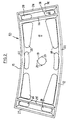
- Figure 2 is a view from below of a second embodiment of a robot end effector according to the invention.
- Figure 3 is a sectional view, on an enlarged scale, taken on the line III-III of Figure 2,
- Figure 4 is a view from below of a third embodiment of a robot end effector according to the invention,
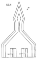
- Figure 5 is a view from below of a fourth embodiment of a robot end effector according to the invention,
- Figure 6 is a view from below of a fifth embodiment of a robot end effector according to the invention,
- Figure 7 is plan of an attachment according to another aspect of the invention for an end effector for clamping a workpiece part to be sewn by means of a gripper pad, and
- Figure 8 is a view in the direction of arrow A in Figure 7.
- Figure 1 shows one embodiment of a robot end effector 1 according to the invention attached to the end of a robot arm 2. The robot arm 2 can be rotated and moved in x, y, z and ϑ directions. The end effector 1 comprises a
rigid backing member 3, facing strip material 4 for contacting a workpiece to slide it across a horizontal work surface and a resilient intermediate layer 5. Themember 3 has window-like openings 6 formed therein to enable escape of air as the end effector 1 is lowered onto a workpiece supported on a work surface. The width w of the strip material 4 is less than the thickness t of the intermediate layer 5. - Figure 2 and 3 show the construction of another embodiment of
robot end effector 10 in greater detail. Theend effector 10 is intended for handling or gripping three different sizes of waist slip fabric having different waist perimeters but the same depth or length. Theend effector 10 comprises a lightweight,rigid packing plate 11, a resilientintermediate layer 12 and a facingsheet 13 of strip like form bonded together to provide a sandwich construction. Thebacking plate 11 is typically 0.5 inch (12.5mm) thick and of composite form comprising a cellular, e.g. honeycomb,structure 14 sandwiched between facingsheets backing plate 11 is sold under the trade name "Aerolam" and consists of an aluminum honeycomb structure sandwiched between aluminum facing sheets. The resilientintermediate layer 12 suitably comprises a high resilient grade polyurethane foam typically having a thickness of from 20mm to 30mm, e.g. 25mm. A suitable foam material is marketed by Dunlopillo under the trade name "DHR 264 Dunloflex". As can be seen from Figure 3, theintermediate layer 12 has a trapezoidal cross-section with its inwardly facing surface angled at an inclined angle (e.g. 45°) to thebacking plate 11. The purpose of this angling is to increase the resistance of thelayer 12 to withstand a shearing movement during traverse of theend effector 10 across a work surface. The facingsheet 13 is conveniently an electrically conductive flexible sheet of friction material, e.g. a rubber sheet containing electrically conductive particles. By using an electricallyconductive sheet 13, static electricity is effectively discharged. Thesheet 13 typically has a thickness of 1mm and each strip has a width (w) no more than 20mm, e.g. 15mm.. Thus the width of each strip of thesheet 13 is no greater than the thickness (t) of theintermediate layer 12. - The
backing plate 11 has a plurality of window-like openings 18 formed therein to allow escape of air as theend effector 10 is lowered towards aworkpiece 64 supported on a flat workingsurface 74. Amounting hole 19 is also formed in theplate 11 to enable theend effector 10 to be secured to the end of a robot arm (not shown) with the aid of bolts (not shown) entered intoholes 20. - The
intermediate layer 12 and facingsheet 13 are arranged stripwise around the entire periphery of thebacking plate 11 along top andbottom regions 21 and 22, respectively, and alongside regions side regions regions regions regions regions 23 and 26 (orregions 24 and 25) are used for manoeuvering a "medium" size waist slip. - The
end effector 10 has a weight of 2.2kg and the total surface area of the facingsheet 13 is 64200 mm². The extra load on theend effector 10 due to the robot coupling is 0.2 kg. In order to obtain efficient workpiece control an extra load of 2.25 kg requires to be applied to theend effector 10. In theory this loading could be applied to the end effector by means of the robot arm. However this centrally applied loading would tend to bend the entire end effector. The preferred method of loading theend effector 10 is therefore to applyweights 28 around the entire periphery of the upper surface of thebacking plate 11. With theweights 28 added, the load/unit area of the facingsheet 13 is 72.4 kg/m². - Other designs of
robot end effectors end effector 10 and where appropriate similar parts have been identified by similar reference numerals. In theend effector 40 window-like apertures are not shown and, in theend effector 50, window-like apertures and a mounting aperture are not shown. In practice, however, such apertures would be provided. - The main additional features of the
end effectors end effector 30 and thestrips 51 and 52 in theend effector 50. These strips enable different sizes of workpiece to be gripped. For example, withend effector 30, the strips 31 - 38 would be employed to grip a workpiece at spaced locations along side edges of the workpiece. - Figures 7 and 8 show an
attachment device 60 which may be attached to anend effector 61. Thedevice 60 comprises agripper pad 62 for grippingscalloped lace 63 to be sewn to afabric piece 64, the stitch line being indicated byreference numeral 65. Thepad 62 is mounted at one end of ahorizontal arm 66 connected to avertical shaft 67 journalled for sliding and pivoting movement in ajournal 68 attached to theend effector 61. The top of theshaft 67 is connected to a furtherhorizontal arm 69 which, in the position shown in Figure 7, rests in aslot 70 forming part of acam surface 71 of acam member 72. Aspring 73 urges thearm 69 into the full line position shown in Figure 7. In use, an upwardly sloping part in front of the sewing head of a sewing machine (not shown) moves relatively to theattachment device 60 along thestitch line 65 and engages beneath thearm 66. As the sewing machine part advances, the sloping part thereof lifts thearm 66 so that thearm 69 is moved out of theslot 70 and thepad 62 is raised clear of thelace 63. The sewing machine part, as it advances along thestitch line 65, pivots thearm 66 about the axis of theshaft 67 so that thepad 62 is swung clear of thestitch line 65 and thearm 69 is moved along thecam surface 71. Finally the sewing machine part clears thearm 66 and thespring 73 pivots the arm back into theslot 70, thegripper pad 62 swinging back over thelace 63 before finally dropping back down into contact with the lace in its original clamping position on, the now sewn-on lace. A number ofsuch devices 61 would be provided on an end effector, the pads of the various end effectors being moved sequentially out of contact and then back into contact with the lace as the sewing progresses along the lace. Theattachment devices 60 may be provided on end effectors according to the present invention. The attachment device shown in Figures 7 and 8 can be used with any design of end effector or gripping device and not just one having the features set out in the following claim 1.
Claims (14)
- A robot end effector (1) comprising a rigid backing member (11), facing strip material (13) arranged to contact a workpiece around, or adjacent to, the periphery of the workpiece and a resilient intermediate layer (12) between the backing member (11) and the facing strip material (13), characterised in that there is at least one void space between the backing member (11) and a plane containing the facing strip material (13) and in that the facing strip material (13) comprises an electrically conductive material.
- A robot end effector according to claim 1, characterised in that the width (w) of the facing strip material (13) is no greater than the thickness (t) of the intermediate layer (12).
- A robot end effector according to claim 1 or 2, further characterised in that the resilient intermediate layer (12) is made of a material which requires a force of from 80 to 120 kg/m², to compress it 1 mm.
- A robot end effector according to claim 1 or 2, further characterised in that the intermediate layer (12) is made of a foam material.
- A robot end effector according to claim 4, characterised in that the foam material is a high resilient grade of polyurethane foam.
- A robot end effector according to claim 1 or 2, characterised in that the width of the intermediate layer (12) where it is adjoined to the backing member (11) is greater than the width of the intermediate layer (12) where it is adjoined to the facing strip material (13).
- A robot end effector according to claim 6, further characterised in that the intermediate layer (12) has a cross-sectional shape such that an inwardly facing side thereof is at an inclined angle to the backing member (11).
- A robot end effector according to claim 6, further characterised in that the intermediate layer (12) has a cross-section of trapezoidal form.
- A robot end effector according to claim 1 or 2, characterised in that the backing member (11) has at least one window-like aperture (6) therein.
- A robot end effector according to claim 1 or 2, characterised in that the rigid backing member (11) comprises a light-weight composite panel (14).
- A robot end effector according to claim 10, characterised in that the composite panel (14) is of laminated construction having a honeycomb core.
- A robot end effector according to any of claims 1 to 11, characterised in that the facing strip material (13) is made of a rubber containing electrically conductive particles.
- A robot end effector according to any of the preceding claims, characterised in that the resilient intermediate layer (12) has a thickness of from 20 mm to 30 mm, and the facing strip material (13) has a width of less than 20 mm.
- A robot end effector according to claim 13, characterised in that the facing strip material (13) has a thickness of substantially 1 mm.
Applications Claiming Priority (3)
| Application Number | Priority Date | Filing Date | Title |
|---|---|---|---|
| GB888823267A GB8823267D0 (en) | 1988-10-04 | 1988-10-04 | Robot end effector |
| GB8823267 | 1988-10-04 | ||
| PCT/GB1989/001170 WO1990003740A1 (en) | 1988-10-04 | 1989-10-03 | A robot end effector |
Publications (2)
| Publication Number | Publication Date |
|---|---|
| EP0437485A1 EP0437485A1 (en) | 1991-07-24 |
| EP0437485B1 true EP0437485B1 (en) | 1994-08-31 |
Family
ID=10644689
Family Applications (1)
| Application Number | Title | Priority Date | Filing Date |
|---|---|---|---|
| EP89911275A Expired - Lifetime EP0437485B1 (en) | 1988-10-04 | 1989-10-03 | A robot end effector |
Country Status (6)
| Country | Link |
|---|---|
| US (1) | US5240299A (en) |
| EP (1) | EP0437485B1 (en) |
| JP (1) | JPH04505891A (en) |
| DE (1) | DE68917932T2 (en) |
| GB (1) | GB8823267D0 (en) |
| WO (1) | WO1990003740A1 (en) |
Families Citing this family (6)
| Publication number | Priority date | Publication date | Assignee | Title |
|---|---|---|---|---|
| US6129031A (en) * | 1999-11-16 | 2000-10-10 | The Boeing Company | Robotic stitching apparatus and end effector therefor |
| USD607477S1 (en) * | 2009-07-24 | 2010-01-05 | Mako Surgical Corp. | Robot arm |
| USD604753S1 (en) * | 2009-07-24 | 2009-11-24 | Mako Surgical Corp. | Robot end effector |
| US9694551B2 (en) * | 2010-11-18 | 2017-07-04 | Pirelli Tyre S.P.A. | Process and apparatus for manufacturing tyres for vehicle wheels |
| FR3109549B1 (en) * | 2020-04-28 | 2023-09-15 | Joulin Cemma | Foam body vacuum gripping head |
| US11826904B2 (en) * | 2020-11-25 | 2023-11-28 | The Boeing Company | End effector, system and method for picking up and placing an object |
Family Cites Families (8)
| Publication number | Priority date | Publication date | Assignee | Title |
|---|---|---|---|---|
| DE1485279B1 (en) * | 1965-10-25 | 1969-10-02 | Pfaff Ag G M | Device for removing the sewn material from sewing machines |
| US3377096A (en) * | 1967-06-02 | 1968-04-09 | Wood S Powr Grip Co Inc | Vacuum gripping pad |
| US3627369A (en) * | 1969-10-10 | 1971-12-14 | Charles H Nixon | High-temperature vacuum pickup |
| FR2495592A1 (en) * | 1980-12-05 | 1982-06-11 | Joulin Sema | GRIPPING DEVICE OPERATING BY SUCCION |
| IL67454A (en) * | 1982-12-10 | 1986-07-31 | Shenkar College Textile Tech | Gripper for automatic cloth handling equipment |
| IT1176164B (en) * | 1984-05-22 | 1987-08-18 | Bini & C Srl | PROCEDURE AND EQUIPMENT FOR LIFTING AND TRANSPORTING OBJECTS PLACED ON TRAY OR SIMILAR SUPPORTS |
| GB8500836D0 (en) * | 1985-01-14 | 1985-02-20 | Courtaulds Clothing Ltd | Unfolding device |
| US5018773A (en) * | 1989-07-14 | 1991-05-28 | Norman M. Stavin | Manual push feeder device for woodworking machines |
-
1988
- 1988-10-04 GB GB888823267A patent/GB8823267D0/en active Pending
-
1989
- 1989-10-03 EP EP89911275A patent/EP0437485B1/en not_active Expired - Lifetime
- 1989-10-03 US US07/678,287 patent/US5240299A/en not_active Expired - Fee Related
- 1989-10-03 JP JP1510508A patent/JPH04505891A/en active Pending
- 1989-10-03 WO PCT/GB1989/001170 patent/WO1990003740A1/en not_active Ceased
- 1989-10-03 DE DE68917932T patent/DE68917932T2/en not_active Expired - Fee Related
Also Published As
| Publication number | Publication date |
|---|---|
| EP0437485A1 (en) | 1991-07-24 |
| GB8823267D0 (en) | 1988-11-09 |
| US5240299A (en) | 1993-08-31 |
| JPH04505891A (en) | 1992-10-15 |
| WO1990003740A1 (en) | 1990-04-19 |
| DE68917932D1 (en) | 1994-10-06 |
| DE68917932T2 (en) | 1995-01-12 |
Similar Documents
| Publication | Publication Date | Title |
|---|---|---|
| EP0768951B1 (en) | Windshield assembly system | |
| JP4035901B2 (en) | Plate material transfer device | |
| US3640562A (en) | Flexible vacuum lifter | |
| CN103534184B (en) | With the tabular component carrying system of lining paper and the method for shifting of this carrying system | |
| US5240299A (en) | Robot end effector | |
| US20140147239A1 (en) | Robot system, suction hand, and method for producing product including workpiece | |
| DE68903694D1 (en) | DEVICE FOR RECORDING INDIVIDUAL OR NEIGHBORING, FLEXIBLE WORKPIECES, THEIR HANDLING AND STORING, IN PARTICULAR OF LEATHER PARTS OR SIMILAR. | |
| IE852452L (en) | Underwater scouring apparatus | |
| JPH0217455B2 (en) | ||
| US3363927A (en) | Device for carrying panels | |
| JPS6216818A (en) | Method and device for automatically operating metallic platein folding work | |
| JPS5947032A (en) | Universal sheet metal holder | |
| CA2951663A1 (en) | Brick layering system | |
| US5520380A (en) | Double pick separator device and flat object unstacking device equipped with this separator | |
| EP0482702B1 (en) | Device for supporting and transporting metal sheets during processing in a punching and/or a shearing machine | |
| US4664589A (en) | Two-handed robot device | |
| AU730908B2 (en) | Method and apparatus for surfacing a board-like object | |
| CN214692183U (en) | Packing paper separating mechanism | |
| AU583611B2 (en) | Handling limp fabric | |
| JPH11300441A (en) | Loader and unloader device having shift function | |
| JP2788177B2 (en) | Film transfer equipment | |
| EP0585508A1 (en) | A device for gripping sheet-like workpieces | |
| Karakerezis et al. | A gripper for handling flat non-rigid materials | |
| EP0135029B1 (en) | Docking and fixing device for a pallet in a robot or like system | |
| JPH02135549U (en) |
Legal Events
| Date | Code | Title | Description |
|---|---|---|---|
| PUAI | Public reference made under article 153(3) epc to a published international application that has entered the european phase |
Free format text: ORIGINAL CODE: 0009012 |
|
| 17P | Request for examination filed |
Effective date: 19910325 |
|
| AK | Designated contracting states |
Kind code of ref document: A1 Designated state(s): DE FR GB IT |
|
| 17Q | First examination report despatched |
Effective date: 19930119 |
|
| ITF | It: translation for a ep patent filed | ||
| GRAA | (expected) grant |
Free format text: ORIGINAL CODE: 0009210 |
|
| AK | Designated contracting states |
Kind code of ref document: B1 Designated state(s): DE FR GB IT |
|
| REF | Corresponds to: |
Ref document number: 68917932 Country of ref document: DE Date of ref document: 19941006 |
|
| ET | Fr: translation filed | ||
| PLBE | No opposition filed within time limit |
Free format text: ORIGINAL CODE: 0009261 |
|
| STAA | Information on the status of an ep patent application or granted ep patent |
Free format text: STATUS: NO OPPOSITION FILED WITHIN TIME LIMIT |
|
| 26N | No opposition filed | ||
| PGFP | Annual fee paid to national office [announced via postgrant information from national office to epo] |
Ref country code: GB Payment date: 19960918 Year of fee payment: 8 |
|
| PGFP | Annual fee paid to national office [announced via postgrant information from national office to epo] |
Ref country code: DE Payment date: 19961227 Year of fee payment: 8 |
|
| PGFP | Annual fee paid to national office [announced via postgrant information from national office to epo] |
Ref country code: FR Payment date: 19970930 Year of fee payment: 9 |
|
| PG25 | Lapsed in a contracting state [announced via postgrant information from national office to epo] |
Ref country code: GB Free format text: LAPSE BECAUSE OF NON-PAYMENT OF DUE FEES Effective date: 19971003 |
|
| GBPC | Gb: european patent ceased through non-payment of renewal fee |
Effective date: 19971003 |
|
| PG25 | Lapsed in a contracting state [announced via postgrant information from national office to epo] |
Ref country code: DE Free format text: LAPSE BECAUSE OF NON-PAYMENT OF DUE FEES Effective date: 19980701 |
|
| REG | Reference to a national code |
Ref country code: FR Ref legal event code: ST |
|
| PG25 | Lapsed in a contracting state [announced via postgrant information from national office to epo] |
Ref country code: FR Free format text: THE PATENT HAS BEEN ANNULLED BY A DECISION OF A NATIONAL AUTHORITY Effective date: 19981031 |
|
| PG25 | Lapsed in a contracting state [announced via postgrant information from national office to epo] |
Ref country code: IT Free format text: LAPSE BECAUSE OF NON-PAYMENT OF DUE FEES;WARNING: LAPSES OF ITALIAN PATENTS WITH EFFECTIVE DATE BEFORE 2007 MAY HAVE OCCURRED AT ANY TIME BEFORE 2007. THE CORRECT EFFECTIVE DATE MAY BE DIFFERENT FROM THE ONE RECORDED. Effective date: 20051003 |