EP0437341A2 - Wandstruktur - Google Patents
Wandstruktur Download PDFInfo
- Publication number
- EP0437341A2 EP0437341A2 EP91300132A EP91300132A EP0437341A2 EP 0437341 A2 EP0437341 A2 EP 0437341A2 EP 91300132 A EP91300132 A EP 91300132A EP 91300132 A EP91300132 A EP 91300132A EP 0437341 A2 EP0437341 A2 EP 0437341A2
- Authority
- EP
- European Patent Office
- Prior art keywords
- barrier
- crowd
- pressure
- force
- parameter
- Prior art date
- Legal status (The legal status is an assumption and is not a legal conclusion. Google has not performed a legal analysis and makes no representation as to the accuracy of the status listed.)
- Granted
Links
Images
Classifications
-
- G—PHYSICS
- G08—SIGNALLING
- G08B—SIGNALLING SYSTEMS, e.g. PERSONAL CALLING SYSTEMS; ORDER TELEGRAPHS; ALARM SYSTEMS
- G08B21/00—Alarms responsive to a single specified undesired or abnormal condition and not otherwise provided for
- G08B21/18—Status alarms
- G08B21/182—Level alarms, e.g. alarms responsive to variables exceeding a threshold
Definitions
- This invention relates to barrier structures for controlling crowds, primarily of people,and to a method of detecting a potential or actual crowd control problem.
- carrier structure herein is intended to include any structure which prevents or impedes the movement of people or animals including temporary or portable structures.
- Barrier structures of various kinds are used to control crowds of people, such as spectators at sports events.
- the crush barriers, handrails, walls and/or fences may be subjected to high, and even excessive, loading, possibly resulting in failure of the structures.
- a crowd control barrier structure comprising barrier means; and means to sense the magnitude of force applied to the barrier means by pressure of a crowd thereagainst.
- the sensing means preferably comprises means to produce an electrical, ultrasonic, optical or hydraulic signal which varies in dependence upon the magnitude of said pressure.
- Said means may comprise at least one strain gauge, load cell or displacement-responsive transducer.
- the sensing means is preferably coupled to a remote monitoring station at which the effect of the force can be monitored.
- a plurality of barrier means may be provided in a particular installation, each provided with respective sensing means, and all of said sensing means may be coupled to a common monitoring station.
- the or each barrier means may comprise a barrier rail, a handrail or a fence supported by a plurality of support members, or may comprise a wall.
- a method of detecting a potential or actual crowd control problem comprising monitoring a parameter of a barrier structure, which parameter varies in dependence upon the magnitude of pressure exerted against the barrier structure by the crowd.
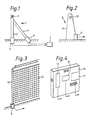
- a barrier structure 1 comprises a plurality of upright posts, such as a post 2, which support a rail 3 or a plurality of rails. At least some of the posts are braced by inclined braces 4. The posts, the rail or rails and the braces may be made of steel, for example.
- a sensor 5 is provided at the base of at least one of the posts to sense a parameter which varies in dependence upon the force applied to the structure 1 as a result of crowd pressure thereagainst.
- the sensor 5 may comprise a strain gauge, the output of which varies as a result of bending of the post under the applied force.
- a sensor 6 may be provided at the base of at least one of the braces. Such sensor may sense tensile or compressive stress induced in the brace.
- sensors (not shown) may be provided in association with the rail itself.
- Each sensor may comprise an individual sensor element or a pack of sensor elements, and each element may comprise a load cell, a strain gauge or a displacement-responsive transducer, depending upon the parameter which is to be sensed.
- the sensors may operate electrically, electronically, magnetically, ultrasonically, by electromagnetic radiation or hydraulically.
- the or each sensor is preferably coupled by wire, a fibre optic cable, a radio, light or ultrasonic link, or a hydraulic line, as the case may be, to a central receiving station 7, at which the signal from the or each sensor can be monitored.
- barrier structures may be provided around the enclosure, each provided with sensors, each of which is coupled to the central receiving station 7 or to another receiving station (not shown).
- signals generated by the sensors are continuously monitored by personnel and/or by automatic monitoring devices at the receiving station or stations. If pressure against any of the barriers reaches a predetermined level at which a potential crowd control or overcrowding problem is indicated, an audible and/or visual alarm is operated and/or automatic or manual means is operated to counter the problem.
- gates may be manually or automatically closed to prevent the entry of further people into the enclosure or into a section of the enclosure. Alternatively or additionally, gates may be opened manually or automatically to allow people to escape from the enclosure.
- Such automatic monitoring devices may be implemented by hardware and/or by a suitable data processor and software.
- Figure 2 shows an alternative form of barrier structure 8 which comprises concrete posts, such as a post 9, supporting a rail 10.
- a sensor 11 is provided at the foot of the post 9 to detect tensile or compressive stress in the post, depending upon the direction of the force applied to the structure by the crowd. Otherwise, the arrangement can be similar to the Figure 1 embodiment.
- Figure 3 shows a similar arrangement, but in which the barrier comprises a fence 12 supported by posts, such as a post 13.
- FIG. 4 shows a wall 14 which includes panels incorporating sensors for sensing pressure exerted against the panels by a crowd.
- panels 15,16 and 17 of various shapes are illustrated.
- alternative and/or additional sensors may be provided at any part of the barrier structure where a parameter changes due to force applied to the structure by pressure from the crowd.
- the monitoring method according to the invention may be used in relation to existing barrier structures by the addition thereto of suitable sensors and associated monitoring equipment.
- suitable sensors and associated monitoring equipment Alternatively, purpose-built barriers incorporating the sensors may be installed.
- the provision of sensors in the barrier structures may also assist in the design of suitable structures for a particular situation.
- the barrier structures may be used in relation to, for example, stadia, sports grounds, arenas and other public enclosures, and may be permanent structures or temporary or portable structures, such as structures erected temporarily for processions, festivals, outdoor meetings or rallies.
- the invention is primarily for use in relation to crowds of people, it might be used in relation to animals.
Landscapes
- Business, Economics & Management (AREA)
- Emergency Management (AREA)
- Physics & Mathematics (AREA)
- General Physics & Mathematics (AREA)
- Emergency Alarm Devices (AREA)
- Burglar Alarm Systems (AREA)
- Fencing (AREA)
Applications Claiming Priority (2)
| Application Number | Priority Date | Filing Date | Title |
|---|---|---|---|
| GB909000553A GB9000553D0 (en) | 1990-01-10 | 1990-01-10 | Barrier structures |
| GB9000553 | 1990-01-10 |
Publications (3)
| Publication Number | Publication Date |
|---|---|
| EP0437341A2 true EP0437341A2 (de) | 1991-07-17 |
| EP0437341A3 EP0437341A3 (en) | 1992-09-02 |
| EP0437341B1 EP0437341B1 (de) | 1997-07-30 |
Family
ID=10669086
Family Applications (1)
| Application Number | Title | Priority Date | Filing Date |
|---|---|---|---|
| EP19910300132 Expired - Lifetime EP0437341B1 (de) | 1990-01-10 | 1991-01-09 | Wandstruktur |
Country Status (3)
| Country | Link |
|---|---|
| EP (1) | EP0437341B1 (de) |
| DE (1) | DE69127000T2 (de) |
| GB (1) | GB9000553D0 (de) |
Cited By (3)
| Publication number | Priority date | Publication date | Assignee | Title |
|---|---|---|---|---|
| WO2016020476A1 (en) * | 2014-08-06 | 2016-02-11 | Agt International Gmbh | Collapsible smart fence |
| DE102015209433A1 (de) * | 2015-05-22 | 2016-11-24 | Oliver Kastens | Sicherheitssystem für ein Veranstaltungsgelände |
| US10914557B2 (en) | 2016-12-09 | 2021-02-09 | Motorola Solutions, Inc. | Method, device, and system for managing a formation of electronically-embedded intelligent shields |
Families Citing this family (1)
| Publication number | Priority date | Publication date | Assignee | Title |
|---|---|---|---|---|
| WO2023147054A1 (en) * | 2022-01-28 | 2023-08-03 | Comprise Technologies, Inc. | Cushioned barricade with crowd surge monitoring and alert system |
Family Cites Families (4)
| Publication number | Priority date | Publication date | Assignee | Title |
|---|---|---|---|---|
| IL60240A (en) * | 1980-06-05 | 1982-07-30 | Beta Eng & Dev Ltd | Intrusion detection system and detectors useful therein |
| GB2162981A (en) * | 1984-08-09 | 1986-02-12 | Shorrock Security Systems Ltd | Intruder detection barrier |
| FR2587057B1 (fr) * | 1985-09-06 | 1987-12-04 | Cloez Gerard | Grille de protection a deverrouillage automatique en cas de panique |
| GB2239272A (en) * | 1989-11-11 | 1991-06-26 | Soltrepac Ltd | Crowd control barrier |
-
1990
- 1990-01-10 GB GB909000553A patent/GB9000553D0/en active Pending
-
1991
- 1991-01-09 DE DE1991627000 patent/DE69127000T2/de not_active Expired - Fee Related
- 1991-01-09 EP EP19910300132 patent/EP0437341B1/de not_active Expired - Lifetime
Cited By (4)
| Publication number | Priority date | Publication date | Assignee | Title |
|---|---|---|---|---|
| WO2016020476A1 (en) * | 2014-08-06 | 2016-02-11 | Agt International Gmbh | Collapsible smart fence |
| DE102015209433A1 (de) * | 2015-05-22 | 2016-11-24 | Oliver Kastens | Sicherheitssystem für ein Veranstaltungsgelände |
| DE102015209433B4 (de) | 2015-05-22 | 2018-06-21 | Oliver Kastens | Verwendung eines Wellenbrechers in einem Sicherheitssystem für ein Veranstaltungsgelände |
| US10914557B2 (en) | 2016-12-09 | 2021-02-09 | Motorola Solutions, Inc. | Method, device, and system for managing a formation of electronically-embedded intelligent shields |
Also Published As
| Publication number | Publication date |
|---|---|
| GB9000553D0 (en) | 1990-03-14 |
| DE69127000D1 (de) | 1997-09-04 |
| EP0437341B1 (de) | 1997-07-30 |
| EP0437341A3 (en) | 1992-09-02 |
| DE69127000T2 (de) | 1998-03-05 |
Similar Documents
| Publication | Publication Date | Title |
|---|---|---|
| US4989835A (en) | Vehicle barrier | |
| US7123785B2 (en) | Optic fiber security fence system | |
| US4858383A (en) | Security enclosure and gate system | |
| KR20220097376A (ko) | 경사지의 보강방법 | |
| US20140259930A1 (en) | Portable gate | |
| KR102166857B1 (ko) | 변위 알림 장치와 이를 포함하는 교량 점검 안전 시설물 및 이의 시공 방법 | |
| KR102148421B1 (ko) | 작업자의 사고를 방지하는 도로 전광판(vms) 시스템 | |
| US4920331A (en) | Security barrier with intrusion sesning and delaying means | |
| JP2011106142A (ja) | 津波シェルター | |
| US4196890A (en) | Security fence | |
| AU6118999A (en) | Intrusion detection fence with trip wires and common actuator | |
| EP0437341B1 (de) | Wandstruktur | |
| WO2009014304A1 (en) | An external trespass sensing system | |
| US4916433A (en) | Protection of property | |
| EP3317863B1 (de) | Übersteigschutz | |
| CN211598025U (zh) | 一种高安全性车间隔离围栏 | |
| CN209958850U (zh) | 一种变电站监控辅助装置 | |
| CN215107217U (zh) | 一种具有安全防护网的脚手架 | |
| GB2171232A (en) | Disturbance sensors for barriers | |
| CN218100375U (zh) | 一种防攀爬电力铁塔 | |
| CN222686318U (zh) | 一种应变式智能围网 | |
| JP7741596B1 (ja) | 盗難防止柵及び盗難防止柵の施工方法 | |
| CN210488720U (zh) | 一种周界防攀爬监测装置、监测架以及防护网 | |
| RU2267574C2 (ru) | Радиооповеститель селя | |
| CN222045294U (zh) | 一种公路施工护栏 |
Legal Events
| Date | Code | Title | Description |
|---|---|---|---|
| PUAI | Public reference made under article 153(3) epc to a published international application that has entered the european phase |
Free format text: ORIGINAL CODE: 0009012 |
|
| AK | Designated contracting states |
Kind code of ref document: A2 Designated state(s): BE DE FR GB IT NL |
|
| PUAL | Search report despatched |
Free format text: ORIGINAL CODE: 0009013 |
|
| AK | Designated contracting states |
Kind code of ref document: A3 Designated state(s): BE DE FR GB IT NL |
|
| 17P | Request for examination filed |
Effective date: 19930226 |
|
| 17Q | First examination report despatched |
Effective date: 19951031 |
|
| RAP1 | Party data changed (applicant data changed or rights of an application transferred) |
Owner name: HAYES, PETER |
|
| GRAG | Despatch of communication of intention to grant |
Free format text: ORIGINAL CODE: EPIDOS AGRA |
|
| GRAH | Despatch of communication of intention to grant a patent |
Free format text: ORIGINAL CODE: EPIDOS IGRA |
|
| GRAH | Despatch of communication of intention to grant a patent |
Free format text: ORIGINAL CODE: EPIDOS IGRA |
|
| GRAA | (expected) grant |
Free format text: ORIGINAL CODE: 0009210 |
|
| AK | Designated contracting states |
Kind code of ref document: B1 Designated state(s): BE DE FR GB IT NL |
|
| PG25 | Lapsed in a contracting state [announced via postgrant information from national office to epo] |
Ref country code: IT Free format text: LAPSE BECAUSE OF FAILURE TO SUBMIT A TRANSLATION OF THE DESCRIPTION OR TO PAY THE FEE WITHIN THE PRE;WARNING: LAPSES OF ITALIAN PATENTS WITH EFFECTIVE DATE BEFORE 2007 MAY HAVE OCCURRED AT ANY TIME BEFORE 2007. THE CORRECT EFFECTIVE DATE MAY BE DIFFERENT FROM THE ONE RECORDED.SCRIBED TIME-LIMIT Effective date: 19970730 Ref country code: BE Effective date: 19970730 Ref country code: NL Free format text: LAPSE BECAUSE OF FAILURE TO SUBMIT A TRANSLATION OF THE DESCRIPTION OR TO PAY THE FEE WITHIN THE PRESCRIBED TIME-LIMIT Effective date: 19970730 |
|
| REF | Corresponds to: |
Ref document number: 69127000 Country of ref document: DE Date of ref document: 19970904 |
|
| ET | Fr: translation filed | ||
| NLV1 | Nl: lapsed or annulled due to failure to fulfill the requirements of art. 29p and 29m of the patents act | ||
| PLBE | No opposition filed within time limit |
Free format text: ORIGINAL CODE: 0009261 |
|
| STAA | Information on the status of an ep patent application or granted ep patent |
Free format text: STATUS: NO OPPOSITION FILED WITHIN TIME LIMIT |
|
| 26N | No opposition filed | ||
| PGFP | Annual fee paid to national office [announced via postgrant information from national office to epo] |
Ref country code: FR Payment date: 20000718 Year of fee payment: 10 |
|
| PGFP | Annual fee paid to national office [announced via postgrant information from national office to epo] |
Ref country code: DE Payment date: 20000724 Year of fee payment: 10 |
|
| PGFP | Annual fee paid to national office [announced via postgrant information from national office to epo] |
Ref country code: GB Payment date: 20010209 Year of fee payment: 11 |
|
| REG | Reference to a national code |
Ref country code: GB Ref legal event code: 732E |
|
| PG25 | Lapsed in a contracting state [announced via postgrant information from national office to epo] |
Ref country code: FR Free format text: LAPSE BECAUSE OF NON-PAYMENT OF DUE FEES Effective date: 20010928 |
|
| PG25 | Lapsed in a contracting state [announced via postgrant information from national office to epo] |
Ref country code: DE Free format text: LAPSE BECAUSE OF NON-PAYMENT OF DUE FEES Effective date: 20011101 |
|
| REG | Reference to a national code |
Ref country code: FR Ref legal event code: ST |
|
| REG | Reference to a national code |
Ref country code: GB Ref legal event code: IF02 |
|
| PG25 | Lapsed in a contracting state [announced via postgrant information from national office to epo] |
Ref country code: GB Free format text: LAPSE BECAUSE OF NON-PAYMENT OF DUE FEES Effective date: 20020109 |
|
| GBPC | Gb: european patent ceased through non-payment of renewal fee |
Effective date: 20020109 |