EP0437070A1 - Séparateur de gaz pour pompe immergée - Google Patents
Séparateur de gaz pour pompe immergée Download PDFInfo
- Publication number
- EP0437070A1 EP0437070A1 EP90313914A EP90313914A EP0437070A1 EP 0437070 A1 EP0437070 A1 EP 0437070A1 EP 90313914 A EP90313914 A EP 90313914A EP 90313914 A EP90313914 A EP 90313914A EP 0437070 A1 EP0437070 A1 EP 0437070A1
- Authority
- EP
- European Patent Office
- Prior art keywords
- liquid
- separator
- chamber
- gas
- pump
- Prior art date
- Legal status (The legal status is an assumption and is not a legal conclusion. Google has not performed a legal analysis and makes no representation as to the accuracy of the status listed.)
- Granted
Links
- 239000007788 liquid Substances 0.000 claims abstract description 129
- 230000003134 recirculating effect Effects 0.000 claims abstract description 72
- 239000012530 fluid Substances 0.000 claims abstract description 55
- 238000011144 upstream manufacturing Methods 0.000 claims abstract description 8
- 238000002347 injection Methods 0.000 claims description 49
- 239000007924 injection Substances 0.000 claims description 49
- 238000000605 extraction Methods 0.000 claims description 47
- 238000000926 separation method Methods 0.000 claims description 14
- 238000005086 pumping Methods 0.000 claims description 9
- 238000000034 method Methods 0.000 claims description 5
- 238000002156 mixing Methods 0.000 claims description 2
- 238000013022 venting Methods 0.000 claims description 2
- 230000000977 initiatory effect Effects 0.000 claims 2
- 238000004064 recycling Methods 0.000 claims 1
- 239000004215 Carbon black (E152) Substances 0.000 description 5
- 229930195733 hydrocarbon Natural products 0.000 description 5
- 150000002430 hydrocarbons Chemical class 0.000 description 5
- 238000004519 manufacturing process Methods 0.000 description 4
- 230000015572 biosynthetic process Effects 0.000 description 3
- XLYOFNOQVPJJNP-UHFFFAOYSA-N water Substances O XLYOFNOQVPJJNP-UHFFFAOYSA-N 0.000 description 3
- 238000010276 construction Methods 0.000 description 2
- 230000007423 decrease Effects 0.000 description 2
- 230000000694 effects Effects 0.000 description 2
- 238000005516 engineering process Methods 0.000 description 2
- 241000239290 Araneae Species 0.000 description 1
- 239000003208 petroleum Substances 0.000 description 1
Images


Classifications
-
- E—FIXED CONSTRUCTIONS
- E21—EARTH OR ROCK DRILLING; MINING
- E21B—EARTH OR ROCK DRILLING; OBTAINING OIL, GAS, WATER, SOLUBLE OR MELTABLE MATERIALS OR A SLURRY OF MINERALS FROM WELLS
- E21B43/00—Methods or apparatus for obtaining oil, gas, water, soluble or meltable materials or a slurry of minerals from wells
- E21B43/34—Arrangements for separating materials produced by the well
- E21B43/38—Arrangements for separating materials produced by the well in the well
-
- B—PERFORMING OPERATIONS; TRANSPORTING
- B01—PHYSICAL OR CHEMICAL PROCESSES OR APPARATUS IN GENERAL
- B01D—SEPARATION
- B01D19/00—Degasification of liquids
- B01D19/0042—Degasification of liquids modifying the liquid flow
- B01D19/0052—Degasification of liquids modifying the liquid flow in rotating vessels, vessels containing movable parts or in which centrifugal movement is caused
-
- E—FIXED CONSTRUCTIONS
- E21—EARTH OR ROCK DRILLING; MINING
- E21B—EARTH OR ROCK DRILLING; OBTAINING OIL, GAS, WATER, SOLUBLE OR MELTABLE MATERIALS OR A SLURRY OF MINERALS FROM WELLS
- E21B43/00—Methods or apparatus for obtaining oil, gas, water, soluble or meltable materials or a slurry of minerals from wells
- E21B43/12—Methods or apparatus for controlling the flow of the obtained fluid to or in wells
- E21B43/121—Lifting well fluids
- E21B43/128—Adaptation of pump systems with down-hole electric drives
-
- F—MECHANICAL ENGINEERING; LIGHTING; HEATING; WEAPONS; BLASTING
- F04—POSITIVE - DISPLACEMENT MACHINES FOR LIQUIDS; PUMPS FOR LIQUIDS OR ELASTIC FLUIDS
- F04D—NON-POSITIVE-DISPLACEMENT PUMPS
- F04D13/00—Pumping installations or systems
- F04D13/02—Units comprising pumps and their driving means
- F04D13/06—Units comprising pumps and their driving means the pump being electrically driven
- F04D13/08—Units comprising pumps and their driving means the pump being electrically driven for submerged use
- F04D13/10—Units comprising pumps and their driving means the pump being electrically driven for submerged use adapted for use in mining bore holes
-
- F—MECHANICAL ENGINEERING; LIGHTING; HEATING; WEAPONS; BLASTING
- F04—POSITIVE - DISPLACEMENT MACHINES FOR LIQUIDS; PUMPS FOR LIQUIDS OR ELASTIC FLUIDS
- F04D—NON-POSITIVE-DISPLACEMENT PUMPS
- F04D31/00—Pumping liquids and elastic fluids at the same time
-
- F—MECHANICAL ENGINEERING; LIGHTING; HEATING; WEAPONS; BLASTING
- F04—POSITIVE - DISPLACEMENT MACHINES FOR LIQUIDS; PUMPS FOR LIQUIDS OR ELASTIC FLUIDS
- F04D—NON-POSITIVE-DISPLACEMENT PUMPS
- F04D9/00—Priming; Preventing vapour lock
- F04D9/001—Preventing vapour lock
Definitions
- the present invention relates generally to the production of liquids from wells, and more particularly to gas separators for separating gas from a well fluid before the well fluid is pumped by a submersible well pump.
- a typical state of the art electric submersible pump rotary gas separator is illustrated in U. S. Patent No. 4,481,020 to Lee et al.
- the gas separator of Lee et al. includes a charging mechanism which initiates axial flow, a separation chamber in which a high energy vortex is developed, and a flow diverting chamber which routes the centrifuged liquids from the perimeter of the separator into the eye of the first stage of the submersible well pump and routes the separated gas from the central area of the separator to exit ports through which it is vented into a well casing annulus.
- the present invention provides a rotary gas separator for separating a well fluid into a liquid and a gas.
- the separator includes a separating chamber, a well fluid inlet upstream of the separating chamber, and a liquid discharge outlet downstream of the separating chamber.
- a means is provided for recirculating a portion of the liquid discharged from the discharge outlet back to the separating chamber so that a gas-to-liquid ratio in the separator means is substantially lower than a gas-to-liquid ratio of well fluid entering the well fluid inlet.
- the result of bypassing or recirculating a portion of the liquid exiting the separator is to reduce the gas-to-liquid ratio entering the separating chamber thus increasing the maximum gas-to-liquid ratio of the incoming well fluid which can be effectively processed by the separator without passing significant amounts of gas into the liquid stream exiting the separator. This increases the well fluid gas-to-liquid ratio which can be pumped by the submersible well pump with the recirculating gas separator.
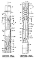
- FIG. 1 is an elevation, cross section partially schematic illustration of a typical prior art rotary gas separator.
- FIG. 2 is an elevation section schematic illustration of an electric submersible well pump with the recirculating rotary gas separator of the present invention.
- FIGS. 3A-3B comprise an elevation section partially schematic illustration of the submersible pump and recirculating gas separator of FIG. 2.
- FIG. 4 is a horizontal cross-sectional view taken along line 4-4 of FIG. 3B.
- FIG. 5 is a horizontal cross-sectional view taken along line 5-5 of FIG. 3A.
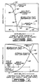
- FIG. 6 is a graphical presentation of head versus rate curves for the electric submersible pump and the recirculating pump.
- FIG. 7 is a graphical illustration of the head versus rate curve for the recirculating pump and the head loss versus rate curve of the external recirculating conduit.
- FIG. 1 illustrates a typical prior art rotary gas separator similar to that shown in U. S. Patent No. 4,481,020 to Lee et al.
- the prior art separator is shown in an elevation cross-section view and is designated generally by the numeral 10.
- An electric submersible pump 12 is schematically illustrated in phantom lines above separator 10.
- a seal unit 14 and an electric motor 16 are schematically illustrated below the separator 10.
- a drive shaft 18 extends from motor 16 upward through the separator 10 to the pump 12 for driving the separator 10 and the pump 12. It will be understood that the shaft 18 is actually a series of shaft segments splined together.
- the separator 10 includes a plurality of well fluid inlets 20 which draw in well fluid, a charging section 22 which initiates generally axial upward flow of the well fluid, a separation section 24 in which a high energy vortex is developed thus separating the upward flowing well fluid into a generally centrally located gas stream and an annular generally radially outwardly located liquid stream, and a flow diverting section 26 which routes the centrifuged liquid through a passage 28 to a discharge outlet 30 communicated with pump 12, and which routes the separated gas from the central area of the separator to exit ports or vent ports 32.
- the improved gas separator apparatus is shown schematically in FIG. 2, and in elevation partially sectioned detail in the enlarged view of FIGS. 3A and 3B.
- the gas separator apparatus which can be referred to as a recirculating gas separator apparatus is generally designated by the numeral 36.
- the recirculating gas separator apparatus 36 is shown schematically in FIG. 2 connected to an electric submersible pump 38 located within a well 40 defined by casing 42.
- the recirculating gas separator 36 includes a rotary gas separator means 44 for separating liquid to be directed to pump 38 from gas.
- the separator means 44 is best shown in FIGS. 3A-3B, and includes a separating chamber 46, a plurality of well fluid inlets 48 located upstream of separating chamber 46, an annular liquid discharge outlet 50 located downstream of separating chamber 46, and a gas vent 52 located downstream of separating chamber 46 for venting gas into the well annulus 54 (see FIG. 2).
- the recirculating gas separator apparatus 36 also includes a recirculating means 56 for recirculating a portion of the liquid discharged from discharge outlet 50 back to the separating chamber 46 so that a gas-to-liquid ratio in the separator means 44 is substantially lower than a gas-to-liquid ratio of well fluid entering the well fluid inlets 48.
- the recirculating means 56 includes a recirculating pump means 58 for pumping liquid from the discharge outlet 50 to the submersible well pump 12 or 38.
- the recirculating means 56 also includes a liquid extraction chamber means 60 for extracting a portion of the liquid discharged by the recirculating pump means 58 before said liquid reaches the submersible pump 12.
- the recirculating means 56 further includes a liquid injection chamber means 62 for injecting said portion of said liquid into said separator means 44 upstream of the separating chamber 46.
- the recirculating means additionally includes conduit means 64 for conducting said portion of said liquid from said liquid extraction chamber means 60 to said liquid injection chamber means 62.
- the liquid injection chamber means 62 is preferably located upstream of the well fluid inlets 48 as shown in FIG. 3B, but could also function if located downstream of well fluid inlets 48.
- the liquid extraction chamber means 60 is located above the recirculating pump means 58.
- the recirculating pump means 58 is located above the separator means 44.
- the separator means 44 is located above the liquid injection chamber means 62.
- a drive motor 66 is located below the liquid injection chamber means 62, with a seal means 68 being located between the drive motor 66 and the liquid injection chamber means 62.
- the drive motor 66 has a drive shaft means 70 extending upward therefrom for driving the separator means 44, the recirculating pump means 58, and the submersible well pump 12. It will be understood that shaft means 70 will typically include a series of coupled shaft segments.
- the submersible well pump 12 pumps liquid upwardly through production tubing 72 to the earth's surface.
- the separator means 44 includes a separator housing 74 having a generally cylindrical outer surface 76 best seen in FIG. 4.
- a possible form of the conduit means 64 includes a plurality of conduits 64A through 64F oriented generally parallel to a longitudinal axis 78 of housing 74 and secured against the cylindrical outer surface 76 by means of a band 80.
- An alternate conduit means could include one large flattened tube.
- the conduits 64A through 64F are surrounded by a conduit guard 82 at those locations where bands such as 80 are placed about the conduit 64A through 64F.
- a motor extension lead 84 (see FIG. 4) is connected to the motor 66 and extends upward along the separator 36 and pump 12. Above pump 12 the lead 84 is splined to a round cable which extends along the production tubing 72 to the earth's surface where it is connected to a source of electrical power. The motor extension lead 84 is also secured against the cylindrical outer surface 76 of separator housing 74 by the bands such as 80. A flat cable guard 86 surrounds extension lead 84 at those locations where the bands 80 surround the extension lead 84.
- conduits 64A through 64F are preferably located adjacent the motor extension lead 84 to maximize clearance of the recirculating gas separator apparatus 36 within the well casing 42.
- the liquid extraction chamber means 60 includes a generally cylindrical extraction chamber housing 88 having an extraction chamber 90 defined therein.
- the housing 88 has a lower end 92 with an annular extraction chamber inlet means 94 defined therein for directing liquid which is pumped by recirculating pump means 58 from the liquid discharge outlet 50 of separator means 44 to the extraction chamber 90.
- the extraction chamber housing 88 has an upper end 96 with an annular extraction chamber outlet means 98 defined therein for directing liquid from the extraction chamber 90 to the submersible well pump 12.
- the extraction chamber housing 88 has an extraction port means 100 defined therein for extracting the portion of liquid flowing through extraction chamber 90 which is to be recirculated through conduit means 64.
- the extraction chamber means 60 further includes a deflection means 102 extending into the extraction chamber 90 for deflecting said portion of said liquid toward the extraction port means 100.
- the deflection means 102 is a ledge which covers approximately one-half the circular cross-sectional area of the extraction chamber 90.
- a bore 104 through this ledge 102 contains a bearing means 106 for supporting the drive shaft 70 which extends downward from the submersible pump 12 through the extraction chamber means 90.
- the liquid injection chamber means 62 includes a generally cylindrical injection chamber housing 108 having an injection chamber 110 defined therein.
- the injection chamber housing 108 has an injection port means 112 defined therein for injecting said portion of said liquid which is recirculated through conduit means 64 into the injection chamber 110.
- the injection chamber housing 108 has an upper end 114 with an annular injection chamber outlet means 116 defined therein for directing said portion of said liquid from said injection chamber means 62 to the separator means 44.
- the injection port means 112 is directed generally downwardly as seen in FIG. 3B.
- the liquid injection chamber means 62 further includes a deflection means 118 for deflecting liquid from the injection port means 112 generally upward into the injection chamber 110.
- the deflection means 118 is constructed similar to the deflection means 102 of FIG. 5, and has a bore therethrough carrying a bearing means 120 for the shaft 70.
- the separator housing 74 has a lower end 122 with a recirculation inlet means 124 defined therein for directing said portion of said liquid from said liquid injection chamber means 62 of said recirculating means 56 into said separation chamber 46.
- the separator housing 74 is made up of an upper separator housing section 126, an intermediate separator housing section 128, and a lower separator housing section 130.
- the well fluid inlets 48 are located in the lower separator housing section 130.
- a spider support 132 is located in the lower end of intermediate separator housing section 128 and includes a plurality of spokes such as 134 extending inward to an annular collar 136 having a bore therein which carries a bearing 138 for the shaft 70.
- a helical blade 142 which can be described as a charging means 142, initiates upward generally axial flow of well fluid and recirculated liquid.
- a plurality of straight radially oriented blades 144 which can also be described as a vortex generating means 144 generate a high energy vortex in the upward flowing fluid for thus separating the fluid radially into a centrally located gas stream and an annular radially outwardly located liquid stream.
- the helical blade 142 and straight blades 144 are integrally constructed and are keyed to the shaft 70 so that they are rotated by the shaft 70 within the separator housing 74.
- annular divider wall 146 which can be described as a flow diverting means 146, directs the annular liquid stream into an outer annular space 148, and directs the centrally located gas stream into a centrally located annular space 150 which flows around the shaft 70.
- the liquid stream flows from outer space 148 through passages like 152 to the annular liquid discharge outlet 50 which leads to recirculating pump means 58.
- the centrally located annular space 150 leads the central gas stream through passages like 154 to gas vents 52.
- liquid injection chamber means 62 and the separator means 44 could be combined into one unit having a common housing.
- the recirculating pump means 58 and the liquid extraction chamber means 60 could be combined.
- the recirculating pump means 58 pumps the liquid from the discharge outlet 50 of separator means 44 through the extraction chamber 90 to the submersible well pump 12. As previously mentioned, a portion of that liquid is extracted from extraction chamber 90 and recirculated through the recirculating conduit means 64.
- the recirculating pump means 58 Since the recirculating pump means 58 must pump all of the fluid which is ultimately pumped by the main electric submersible pump 12, plus all of the fluid which is recirculated, the recirculating pump means 58 should have a significantly higher flow rate at its operating point than does the submersible well pump l2 at its operating point.
- the recirculating pump means 58 preferably is a centrifugal pump which may be composed of as few as one or two stages.
- FIG. 6 is a graphical illustration of the head versus rate curves for the main submersible well pump 38 and for the recirculating pump 58.
- Curve 156 represents the performance curve for the main submersible well pump 38.
- a centrifugal pump has a curve like curve 156 along which the pump operates.
- the main pump 38 will have a preferred operating range 158.
- the pump 38 will be operated at the point on curve 156 known as the best efficiency point (BEP) 160 having a corresponding flow rate 161.
- BEP best efficiency point
- the recirculating pump means 58 will have an operating curve 162 with a preferred operating range 164.
- the recirculating pump means 58 should be chosen so that it operates at an operating point 166 somewhere within its preferred operating range 164 at a flow rate 167 substantially greater than the flow rate of the main pump 38 when main pump 38 is operating at its best efficiency point 160.
- curve 168 which represents the head loss through the fluid conduit means 64 for various flow rates.
- the rate of recirculation of liquid through conduit means 64 equals the pumping rate 167 of the recirculating pump means 58 minus the pumping rate 161 of the main pump 38, and is governed by the head loss through the external recirculating conduit means 64.
- the main pump 38 is operating at flow rate 161 noted on the horizontal axis in FIGS. 6 and 7.
- the recirculating pump means 58 is pumping at a flow rate 167 also indicated on the horizontal axis of FIGS. 6 and 7. It is noted that the scale of the vertical axis in FIG. 7 has been modified as compared to FIG. 6.
- Flow data for one possible size, namely 0.5 inch diameter by 0.049 inch wall thickness, recirculating tube 64A is summarized in the following Table I. This data was calculated assuming an effective tube length of six feet. It may be observed that flow rates ranging from 150 to 336 barrels per day result in head losses ranging from ten to fifty feet. Rates much in excess of 336 barrels per day would probably be undesirable for the 1 ⁇ 2" x 0.049" tubes because of erosional effects.
- Equation 1 The volume percent gas entering a conventional rotary gas separator (such as separator 10 of FIG. 1) and entering a recirculating gas separator (such as separator 36 of FIGS. 3A-3B) is expressed in Equations 1 and 2, respectively.
- One source for the formation volume factors used in these equations is Standing, M. B.: Oilfield Hydrocarbon Systems, Reinhold Publishing Corp., New York City (1952).
- Equation 4 Equation 4
- the foregoing example illustrates the ability of the recirculating separator 36 to handle considerably larger volumes of gas than the conventional rotary gas separator 10.
- Selection of recirculating pump 58 having a recirculating flow rate through conduit means 64 twice the rate of production of well fluids into well fluid inlet 48 provided an increase in GLR from 500 scf/bbl. to 1350 scf/bbl. Selection of an even higher volume recirculating pump 58 would have further increased the gas handling capacity of the recirculating gas separator 36.
Landscapes
- Engineering & Computer Science (AREA)
- Mining & Mineral Resources (AREA)
- Life Sciences & Earth Sciences (AREA)
- Geology (AREA)
- Mechanical Engineering (AREA)
- General Engineering & Computer Science (AREA)
- Geochemistry & Mineralogy (AREA)
- Physics & Mathematics (AREA)
- Environmental & Geological Engineering (AREA)
- Fluid Mechanics (AREA)
- General Life Sciences & Earth Sciences (AREA)
- Chemical Kinetics & Catalysis (AREA)
- Chemical & Material Sciences (AREA)
- Structures Of Non-Positive Displacement Pumps (AREA)
- Compressor (AREA)
- Gas Separation By Absorption (AREA)
- Details Of Reciprocating Pumps (AREA)
Applications Claiming Priority (2)
| Application Number | Priority Date | Filing Date | Title |
|---|---|---|---|
| US07/462,667 US4981175A (en) | 1990-01-09 | 1990-01-09 | Recirculating gas separator for electric submersible pumps |
| US462667 | 1990-01-09 |
Publications (2)
| Publication Number | Publication Date |
|---|---|
| EP0437070A1 true EP0437070A1 (fr) | 1991-07-17 |
| EP0437070B1 EP0437070B1 (fr) | 1994-03-16 |
Family
ID=23837318
Family Applications (1)
| Application Number | Title | Priority Date | Filing Date |
|---|---|---|---|
| EP90313914A Expired - Lifetime EP0437070B1 (fr) | 1990-01-09 | 1990-12-19 | Séparateur de gaz pour pompe immergée |
Country Status (4)
| Country | Link |
|---|---|
| US (1) | US4981175A (fr) |
| EP (1) | EP0437070B1 (fr) |
| CA (1) | CA2027432A1 (fr) |
| NO (1) | NO301661B1 (fr) |
Cited By (4)
| Publication number | Priority date | Publication date | Assignee | Title |
|---|---|---|---|---|
| WO1993013318A1 (fr) * | 1991-12-30 | 1993-07-08 | Framo Developments (Uk) Limited | Traitement d'un systeme fluide a plusieurs phases |
| WO2005045189A1 (fr) * | 2003-10-27 | 2005-05-19 | Joh. Heinr. Bornemann Gmbh | Procede pour refouler des melanges a phases multiples et installation de pompage |
| RU2467166C1 (ru) * | 2011-05-31 | 2012-11-20 | Максим Николаевич Шурыгин | Скважинный сепаратор и способ разделения жидкости с помощью него |
| US8764386B2 (en) | 2005-05-24 | 2014-07-01 | Franklin Electric Co., Inc. | Bypass system for purging air from a submersible pump |
Families Citing this family (69)
| Publication number | Priority date | Publication date | Assignee | Title |
|---|---|---|---|---|
| FR2652610B1 (fr) * | 1989-09-29 | 1992-01-03 | Elf Aquitaine | Procede de pompage de melange liquide gaz dans un puits d'extraction petrolier et dispositif de mise en óoeuvre du procede. |
| EP0699270B1 (fr) * | 1993-04-27 | 2001-10-17 | Atlantic Richfield Company | Separateur gaz-liquides de fond pour puits |
| US5516360A (en) * | 1994-04-08 | 1996-05-14 | Baker Hughes Incorporated | Abrasion resistant gas separator |
| US5456837A (en) * | 1994-04-13 | 1995-10-10 | Centre For Frontier Engineering Research Institute | Multiple cyclone apparatus for downhole cyclone oil/water separation |
| TW312079B (fr) * | 1994-06-06 | 1997-08-01 | Ibm | |
| US5474601A (en) * | 1994-08-02 | 1995-12-12 | Conoco Inc. | Integrated floating platform vertical annular separation and pumping system for production of hydrocarbons |
| US5525146A (en) * | 1994-11-01 | 1996-06-11 | Camco International Inc. | Rotary gas separator |
| US5570744A (en) * | 1994-11-28 | 1996-11-05 | Atlantic Richfield Company | Separator systems for well production fluids |
| US5482117A (en) * | 1994-12-13 | 1996-01-09 | Atlantic Richfield Company | Gas-liquid separator for well pumps |
| EP0830494B1 (fr) * | 1995-06-07 | 2000-03-29 | Centre For Engineering Research Inc. | Procede de cyclonage de fond de puits |
| US5622222A (en) * | 1995-09-26 | 1997-04-22 | Mobil Oil Corporation | Scavenger system and electrical submersible pumps (ESP's) |
| US5845709A (en) * | 1996-01-16 | 1998-12-08 | Baker Hughes Incorporated | Recirculating pump for electrical submersible pump system |
| FR2748532B1 (fr) * | 1996-05-07 | 1999-07-16 | Inst Francais Du Petrole | Systeme de pompage polyphasique et centrifuge |
| FR2748533B1 (fr) * | 1996-05-07 | 1999-07-23 | Inst Francais Du Petrole | Systeme de pompage polyphasique et centrifuge |
| US5794697A (en) * | 1996-11-27 | 1998-08-18 | Atlantic Richfield Company | Method for increasing oil production from an oil well producing a mixture of oil and gas |
| US5821406A (en) * | 1997-02-27 | 1998-10-13 | Koch Industries, Inc. | Crude oil measurement system and method |
| US5963037A (en) * | 1997-08-06 | 1999-10-05 | Atlantic Richfield Company | Method for generating a flow profile of a wellbore using resistivity logs |
| BR9704499A (pt) * | 1997-08-26 | 1999-12-07 | Petroleo Brasileiro Sa | Separador helicoidal aperfeiçoado |
| US5970422A (en) * | 1997-09-29 | 1999-10-19 | Atlantic Richfield Company | Method for generating a flow profile of a wellbore from pulsed neutron logs |
| US5992521A (en) * | 1997-12-02 | 1999-11-30 | Atlantic Richfield Company | Method and system for increasing oil production from an oil well producing a mixture of oil and gas |
| US6260004B1 (en) * | 1997-12-31 | 2001-07-10 | Innovation Management Group, Inc. | Method and apparatus for diagnosing a pump system |
| FR2774136B1 (fr) * | 1998-01-28 | 2000-02-25 | Inst Francais Du Petrole | Dispositif de compression-pompage monoarbre associe a un separateur |
| US6056054A (en) * | 1998-01-30 | 2000-05-02 | Atlantic Richfield Company | Method and system for separating and injecting water in a wellbore |
| US6138757A (en) * | 1998-02-24 | 2000-10-31 | Bj Services Company U.S.A. | Apparatus and method for downhole fluid phase separation |
| US6035934A (en) * | 1998-02-24 | 2000-03-14 | Atlantic Richfield Company | Method and system for separating and injecting gas in a wellbore |
| US6032737A (en) * | 1998-04-07 | 2000-03-07 | Atlantic Richfield Company | Method and system for increasing oil production from an oil well producing a mixture of oil and gas |
| US6026901A (en) * | 1998-06-01 | 2000-02-22 | Atlantic Richfield Company | Method and system for separating and injecting gas in a wellbore |
| US6066193A (en) * | 1998-08-21 | 2000-05-23 | Camco International, Inc. | Tapered flow gas separation system |
| US6116338A (en) * | 1998-09-09 | 2000-09-12 | Green Country Supply, Inc. | Inducer for increasing centrifugal pump efficiency in wells producing high viscosity crude oil |
| US5988275A (en) * | 1998-09-22 | 1999-11-23 | Atlantic Richfield Company | Method and system for separating and injecting gas and water in a wellbore |
| US6155345A (en) * | 1999-01-14 | 2000-12-05 | Camco International, Inc. | Downhole gas separator having multiple separation chambers |
| US6391190B1 (en) | 1999-03-04 | 2002-05-21 | Aec Oil Sands, L.P. | Mechanical deaeration of bituminous froth |
| US6260619B1 (en) | 1999-07-13 | 2001-07-17 | Atlantic Richfield Company | Oil and gas production with downhole separation and compression of gas |
| BR9905912A (pt) | 1999-12-20 | 2001-07-24 | Petroleo Brasileiro Sa | Separador de gás de fundo de poço |
| BR0000183A (pt) | 2000-01-27 | 2001-10-02 | Petroleo Brasileira S A Petrob | Separador de gás dotado de controle automático de nìvel |
| US6382317B1 (en) | 2000-05-08 | 2002-05-07 | Delwin E. Cobb | Apparatus and method for separating gas and solids from well fluids |
| CA2388070C (fr) * | 2001-05-30 | 2006-05-23 | Baker Hughes Incorporated | Separateur de gaz ameliore |
| US6668925B2 (en) | 2002-02-01 | 2003-12-30 | Baker Hughes Incorporated | ESP pump for gassy wells |
| US6684946B2 (en) | 2002-04-12 | 2004-02-03 | Baker Hughes Incorporated | Gas-lock re-prime device for submersible pumps and related methods |
| US6964299B2 (en) * | 2003-08-13 | 2005-11-15 | Schlumberger Technology Corporation | Submersible pumping system |
| US7462225B1 (en) | 2004-09-15 | 2008-12-09 | Wood Group Esp, Inc. | Gas separator agitator assembly |
| US7188669B2 (en) * | 2004-10-14 | 2007-03-13 | Baker Hughes Incorporated | Motor cooler for submersible pump |
| US7357186B1 (en) * | 2005-04-15 | 2008-04-15 | Wood Group Esp, Inc. | Recirculation gas separator |
| US8322434B2 (en) * | 2005-08-09 | 2012-12-04 | Exxonmobil Upstream Research Company | Vertical annular separation and pumping system with outer annulus liquid discharge arrangement |
| US8136600B2 (en) * | 2005-08-09 | 2012-03-20 | Exxonmobil Upstream Research Company | Vertical annular separation and pumping system with integrated pump shroud and baffle |
| US7461692B1 (en) | 2005-12-15 | 2008-12-09 | Wood Group Esp, Inc. | Multi-stage gas separator |
| US7695549B2 (en) * | 2006-09-26 | 2010-04-13 | Global Oilfield Services Llc | Fluid filtration tool |
| US7695548B1 (en) * | 2006-09-26 | 2010-04-13 | Global Oilfield Services Llc | Fluid filtration tool |
| EP2134971B1 (fr) * | 2007-03-08 | 2018-01-10 | Sulzer Management AG | Système de pompe et procédé destiné à pomper des mélanges polyphasés |
| US7883570B2 (en) | 2007-10-01 | 2011-02-08 | Star Oil Tools Inc. | Spiral gas separator |
| US7708059B2 (en) * | 2007-11-13 | 2010-05-04 | Baker Hughes Incorporated | Subsea well having a submersible pump assembly with a gas separator located at the pump discharge |
| US7841395B2 (en) * | 2007-12-21 | 2010-11-30 | Baker Hughes Incorporated | Electric submersible pump (ESP) with recirculation capability |
| US20090194295A1 (en) * | 2008-02-04 | 2009-08-06 | Baker Hughes Incorporated | System, method and apparatus for electrical submersible pump with integrated gas separator |
| WO2011099888A1 (fr) * | 2010-02-15 | 2011-08-18 | Limited Liability Corparation "Whormholes" | Dispositif de régulation d'écoulement d'entrée pour un puits de production ou d'injection |
| US9518458B2 (en) | 2012-10-22 | 2016-12-13 | Blackjack Production Tools, Inc. | Gas separator assembly for generating artificial sump inside well casing |
| US9283497B2 (en) * | 2013-02-01 | 2016-03-15 | Ge Oil & Gas Esp, Inc. | Abrasion resistant gas separator |
| US20150099448A1 (en) * | 2013-10-08 | 2015-04-09 | Ge Oil & Gas Esp, Inc. | Vent box |
| US10227986B2 (en) | 2013-12-12 | 2019-03-12 | General Electric Company | Pumping system for a wellbore and methods of assembling the same |
| US9932806B2 (en) * | 2014-04-28 | 2018-04-03 | Summit Esp, Llc | Apparatus, system and method for reducing gas to liquid ratios in submersible pump applications |
| US10463990B2 (en) | 2015-12-14 | 2019-11-05 | General Electric Company | Multiphase pumping system with recuperative cooling |
| US10927653B2 (en) | 2017-03-10 | 2021-02-23 | Halliburton Energy Services, Inc. | Apparatus, system and method for flow rate harmonization in electric submersible pump gas separators |
| WO2018164962A1 (fr) * | 2017-03-10 | 2018-09-13 | Halliburton Energy Services, Inc. | Appareil, système et procédé d'harmonisation du débit dans des séparateurs de gaz de pompe submersible électrique |
| US10344580B2 (en) | 2017-05-03 | 2019-07-09 | Ge Oil & Gas Esp, Inc. | Passive multiphase flow separator |
| US10731452B2 (en) | 2017-08-16 | 2020-08-04 | Blackjack Production Tools, Llc | Gas separator assembly with degradable material |
| CA3132046A1 (fr) | 2019-03-11 | 2020-09-17 | Blackjack Production Tools, Llc | Separateur de gaz de fond de trou a entree limitee et a etages multiples |
| US11448055B2 (en) | 2019-05-16 | 2022-09-20 | David C. Wright | Subsea duplex pump, subsea pumping system, and subsea pumping method |
| US11248628B2 (en) * | 2019-11-15 | 2022-02-15 | Halliburton Energy Services, Inc. | Electric submersible pump (ESP) gas slug mitigation system |
| CA3151990A1 (fr) | 2019-12-20 | 2021-06-24 | Blackjack Production Tools, Llc | Appareil pour localiser et isoler une admission de pompe dans un puits de petrole et de gaz a l'aide d'un separateur de gaz de tubage |
| US20240229624A1 (en) * | 2023-01-11 | 2024-07-11 | Championx Llc | Downhole centrifugal pumps including locking features and related components and methods |
Citations (1)
| Publication number | Priority date | Publication date | Assignee | Title |
|---|---|---|---|---|
| GB2215408A (en) * | 1988-02-29 | 1989-09-20 | Shell Int Research | Method and system for controlling the gas-liquid ratio in a pump |
Family Cites Families (11)
| Publication number | Priority date | Publication date | Assignee | Title |
|---|---|---|---|---|
| US2285169A (en) * | 1938-06-27 | 1942-06-02 | Union Oil Co | Well pump |
| US2311963A (en) * | 1939-07-11 | 1943-02-23 | Union Oil Co | Gas anchor |
| US2525233A (en) * | 1947-06-16 | 1950-10-10 | Sidney A Miller | Gas and oil separator |
| US3624822A (en) * | 1970-04-17 | 1971-11-30 | Oil Dynamics Inc | Gas separator for a submersible oil pump |
| US3887342A (en) * | 1972-11-10 | 1975-06-03 | Fmc Corp | Liquid-gas separator unit |
| US4330306A (en) * | 1975-10-08 | 1982-05-18 | Centrilift-Hughes, Inc. | Gas-liquid separator |
| US4088459A (en) * | 1976-12-20 | 1978-05-09 | Borg-Warner Corporation | Separator |
| US4231767A (en) * | 1978-10-23 | 1980-11-04 | Trw Inc. | Liquid-gas separator apparatus |
| US4481020A (en) * | 1982-06-10 | 1984-11-06 | Trw Inc. | Liquid-gas separator apparatus |
| US4676308A (en) * | 1985-11-22 | 1987-06-30 | Chevron Research Company | Down-hole gas anchor device |
| US4766957A (en) * | 1987-07-28 | 1988-08-30 | Mcintyre Jack W | Method and apparatus for removing excess water from subterranean wells |
-
1990
- 1990-01-09 US US07/462,667 patent/US4981175A/en not_active Expired - Fee Related
- 1990-10-12 CA CA002027432A patent/CA2027432A1/fr not_active Abandoned
- 1990-10-12 NO NO904428A patent/NO301661B1/no not_active IP Right Cessation
- 1990-12-19 EP EP90313914A patent/EP0437070B1/fr not_active Expired - Lifetime
Patent Citations (1)
| Publication number | Priority date | Publication date | Assignee | Title |
|---|---|---|---|---|
| GB2215408A (en) * | 1988-02-29 | 1989-09-20 | Shell Int Research | Method and system for controlling the gas-liquid ratio in a pump |
Cited By (8)
| Publication number | Priority date | Publication date | Assignee | Title |
|---|---|---|---|---|
| WO1993013318A1 (fr) * | 1991-12-30 | 1993-07-08 | Framo Developments (Uk) Limited | Traitement d'un systeme fluide a plusieurs phases |
| US5575615A (en) * | 1991-12-30 | 1996-11-19 | Framo Developments (Uk) Limited | Multiphase fluid treatment |
| US5580214A (en) * | 1991-12-30 | 1996-12-03 | Framo Developments (Uk) Limited | Multiphase fluid treatment |
| WO2005045189A1 (fr) * | 2003-10-27 | 2005-05-19 | Joh. Heinr. Bornemann Gmbh | Procede pour refouler des melanges a phases multiples et installation de pompage |
| CN1867753B (zh) * | 2003-10-27 | 2010-09-22 | 约翰·海因里希·波内曼有限公司 | 用于输送多相混合物的方法和泵装置 |
| US7810572B2 (en) | 2003-10-27 | 2010-10-12 | Joh. Heinr. Bornemann Gmbh | Method for delivering a multi phase mixture and pump installation |
| US8764386B2 (en) | 2005-05-24 | 2014-07-01 | Franklin Electric Co., Inc. | Bypass system for purging air from a submersible pump |
| RU2467166C1 (ru) * | 2011-05-31 | 2012-11-20 | Максим Николаевич Шурыгин | Скважинный сепаратор и способ разделения жидкости с помощью него |
Also Published As
| Publication number | Publication date |
|---|---|
| NO904428L (no) | 1991-07-10 |
| NO904428D0 (no) | 1990-10-12 |
| EP0437070B1 (fr) | 1994-03-16 |
| CA2027432A1 (fr) | 1991-07-10 |
| NO301661B1 (no) | 1997-11-24 |
| US4981175A (en) | 1991-01-01 |
Similar Documents
| Publication | Publication Date | Title |
|---|---|---|
| EP0437070B1 (fr) | Séparateur de gaz pour pompe immergée | |
| US7766081B2 (en) | Gas separator within ESP shroud | |
| CA2543460C (fr) | Pompe a debit de croisement a deux phases | |
| US8141625B2 (en) | Gas boost circulation system | |
| US6113675A (en) | Gas separator having a low rotating mass | |
| CA2510497C (fr) | Coude de croisement de fluides a separateur de gaz pour pompe de puits | |
| CA2557098C (fr) | Conditionneur d'ecoulement biphase pour le pompage de fluide gazeux dans des puits | |
| US7461692B1 (en) | Multi-stage gas separator | |
| US10107274B2 (en) | Electrical submersible pump assembly for separating gas and oil | |
| US20070062374A1 (en) | Gas separator | |
| US20030141056A1 (en) | Below motor well fluid separation and conditioning | |
| US9388679B2 (en) | Downhole gas and liquid separation | |
| US8424597B2 (en) | Downhole gas and liquid separation | |
| AU2005287828B2 (en) | Gas separator | |
| GB2124929A (en) | Liquid gas separator | |
| US3972352A (en) | Discharge element for a liquid-gas separator unit | |
| US6105671A (en) | Method and apparatus for minimizing emulsion formation in a pumped oil well | |
| US20110073305A1 (en) | Multisection Downhole Separator and Method | |
| US11268516B2 (en) | Gas-lock re-prime shaft passage in submersible well pump and method of re-priming the pump | |
| US11753920B1 (en) | Parallel gas separator, and submersible pump assembly and method | |
| US20240133381A1 (en) | Intakes and gas separators for downhole pumps, and related apparatuses and methods | |
| KR880000779B1 (ko) | 액체-가스 분리장치 | |
| CA2363620C (fr) | Pompe centrifuge avec admission induit |
Legal Events
| Date | Code | Title | Description |
|---|---|---|---|
| PUAI | Public reference made under article 153(3) epc to a published international application that has entered the european phase |
Free format text: ORIGINAL CODE: 0009012 |
|
| AK | Designated contracting states |
Kind code of ref document: A1 Designated state(s): GB NL |
|
| 17P | Request for examination filed |
Effective date: 19920103 |
|
| 17Q | First examination report despatched |
Effective date: 19921214 |
|
| GRAA | (expected) grant |
Free format text: ORIGINAL CODE: 0009210 |
|
| AK | Designated contracting states |
Kind code of ref document: B1 Designated state(s): GB NL |
|
| PG25 | Lapsed in a contracting state [announced via postgrant information from national office to epo] |
Ref country code: NL Effective date: 19940316 |
|
| NLV1 | Nl: lapsed or annulled due to failure to fulfill the requirements of art. 29p and 29m of the patents act | ||
| PLBE | No opposition filed within time limit |
Free format text: ORIGINAL CODE: 0009261 |
|
| STAA | Information on the status of an ep patent application or granted ep patent |
Free format text: STATUS: NO OPPOSITION FILED WITHIN TIME LIMIT |
|
| 26N | No opposition filed | ||
| K1C1 | Correction of patent application (title page) published |
Effective date: 19910717 |
|
| REG | Reference to a national code |
Ref country code: GB Ref legal event code: 732E |
|
| PGFP | Annual fee paid to national office [announced via postgrant information from national office to epo] |
Ref country code: GB Payment date: 19991203 Year of fee payment: 10 |
|
| PG25 | Lapsed in a contracting state [announced via postgrant information from national office to epo] |
Ref country code: GB Free format text: LAPSE BECAUSE OF NON-PAYMENT OF DUE FEES Effective date: 20001219 |
|
| GBPC | Gb: european patent ceased through non-payment of renewal fee |
Effective date: 20001219 |