EP0436294B1 - Buckle for seat belt - Google Patents
Buckle for seat belt Download PDFInfo
- Publication number
- EP0436294B1 EP0436294B1 EP19900312773 EP90312773A EP0436294B1 EP 0436294 B1 EP0436294 B1 EP 0436294B1 EP 19900312773 EP19900312773 EP 19900312773 EP 90312773 A EP90312773 A EP 90312773A EP 0436294 B1 EP0436294 B1 EP 0436294B1
- Authority
- EP
- European Patent Office
- Prior art keywords
- latching
- buckle
- formation
- tongue
- tongues
- Prior art date
- Legal status (The legal status is an assumption and is not a legal conclusion. Google has not performed a legal analysis and makes no representation as to the accuracy of the status listed.)
- Expired - Lifetime
Links
- 210000002105 tongue Anatomy 0.000 claims description 62
- 230000015572 biosynthetic process Effects 0.000 claims description 44
- 238000005755 formation reaction Methods 0.000 claims description 44
- 230000000903 blocking effect Effects 0.000 claims description 23
- 238000006073 displacement reaction Methods 0.000 claims description 4
- 230000037431 insertion Effects 0.000 claims description 3
- 238000003780 insertion Methods 0.000 claims description 3
- 230000000994 depressogenic effect Effects 0.000 description 3
- 230000006835 compression Effects 0.000 description 1
- 238000007906 compression Methods 0.000 description 1
- 238000005192 partition Methods 0.000 description 1
- 230000000717 retained effect Effects 0.000 description 1
Images



Classifications
-
- A—HUMAN NECESSITIES
- A44—HABERDASHERY; JEWELLERY
- A44B—BUTTONS, PINS, BUCKLES, SLIDE FASTENERS, OR THE LIKE
- A44B11/00—Buckles; Similar fasteners for interconnecting straps or the like, e.g. for safety belts
- A44B11/25—Buckles; Similar fasteners for interconnecting straps or the like, e.g. for safety belts with two or more separable parts
- A44B11/2503—Safety buckles
- A44B11/2546—Details
- A44B11/2549—Fastening of other buckle elements to the main buckle
-
- A—HUMAN NECESSITIES
- A44—HABERDASHERY; JEWELLERY
- A44B—BUTTONS, PINS, BUCKLES, SLIDE FASTENERS, OR THE LIKE
- A44B11/00—Buckles; Similar fasteners for interconnecting straps or the like, e.g. for safety belts
- A44B11/25—Buckles; Similar fasteners for interconnecting straps or the like, e.g. for safety belts with two or more separable parts
- A44B11/2503—Safety buckles
- A44B11/2507—Safety buckles actuated by a push-button
- A44B11/2511—Safety buckles actuated by a push-button acting perpendicularly to the main plane of the buckle, e.g. placed on the front face of the buckle
-
- A—HUMAN NECESSITIES
- A44—HABERDASHERY; JEWELLERY
- A44B—BUTTONS, PINS, BUCKLES, SLIDE FASTENERS, OR THE LIKE
- A44B11/00—Buckles; Similar fasteners for interconnecting straps or the like, e.g. for safety belts
- A44B11/25—Buckles; Similar fasteners for interconnecting straps or the like, e.g. for safety belts with two or more separable parts
- A44B11/2503—Safety buckles
- A44B11/2546—Details
- A44B11/2561—Tongue elements
Definitions
- This invention relates to a buckle for a seat belt, comprising a buckle housing and two tongues, the buckle housing containing a latching mechanism having a latching formation for each tongue.
- US-A-3523342 discloses a buckle of this type in which the latching formations are arranged for angular movement about respective spaced mutually parallel pivot axes between locking positions in which they engage with respective latch-engaging surfaces on the tongues to prevent removal of the tongues from the buckle housing and a release position in which the tongues are removable from the buckle housing.
- the latching formations are shaped so that a force applied to a tongue in a direction to remove it from the buckle housing tends to cause displacement of the corresponding latching formation from its locking position to its release position.
- EP-A-0289762 discloses a buckle of this type in which the latching formations are arranged for angular movement between a locking position in which they confront one another and the two tongues are retained therebetween in the buckle housing, and a release position in which the tongue is removable from the buckle housing.
- US-A-3648333 discloses a buckle having a single tongue, in which the latching formations are arranged for angular movement about respective spaced mutually parallel pivot axes between locking positions in which they engage with respective latch-engaging surfaces on the tongue to prevent removal of the tongue from the buckle housing and a release position in which the tongue is removable from the buckle housing.
- Blocking means are manually movable between a release position and a blocking position in which movement of the latching formations from their locked positions to their release positions is obstructed.
- Each latching formation is arranged so that, when in its release position, it prevents movement of the blocking means into its blocking position.
- the invention provides a buckle for a seat belt, comprising a buckle housing and two tongues, the buckle housing containing a latching mechanism having a latching formation for each tongue, the latching formations being arranged for angular movement about respective spaced mutually parallel pivot axes between locking positions in which they engage with respective latch-engaging surfaces on the tongues to prevent removal of the tongues from the buckle housing and a release position in which the tongues are removable from the buckle housing, blocking means being manually movable between a blocking position in which it obstructs movement of the latching formations from their locked positions to their release positions and a release position in which the latching formations are free to move between their locking positions and their release positions, each latching formation being shaped so that a force applied to a tongue in a direction to remove it from the buckle housing tends to cause displacement of the corresponding latching formation from its locking position to its release position, and each latching formation being arranged so that, when in its release position, it prevents movement of the blocking means into its blocking position.
- This arrangement prevents the buckle being fastened with only one tongue in place.
- each latching formation includes an ejector formation shaped to engage with its respective tongue so that movement of the latching formation from its locking position to its release position ejects the tongue, and insertion of the tongue moves the latching formation from its release position to its locked position.
- each latching formation comprises a latching lever mounted with its pivot axis at an intermediate position along its length, one end of each latching lever being arranged to engage with the corresponding tongue and the other end of each latching lever being arranged to engage with the blocking means.
- the buckle comprises a buckle housing 10 and two tongues 12 and 14, having respective slots 16, 18 and 20 whereby they may be connected to respective straps (not shown) of a seat belt system.
- the housing 10 is formed in two parts 22 and 24 for ease of assembly.
- the two parts 22 and 24 are shown as integral with one another.
- the portions of the tongues 12 and 14 which are insertable into the housing 10 have respective hook formations with latch-engaging surfaces 26 and 28 and ejector-engaging surfaces 30 and 32.
- the upper tongue 18 (as viewed in Figure 1) has a peg 34 which can be inserted into a corresponding recess 36 in the other tongue 14.
- the buckle housing 10 has two openings 34 and 36 for receiving the tongues 12 and 14 respectively.
- the openings 34 and 36 are separated by a central partition 38, behind which are located a pair of latching levers 40 and 42.
- these latching levers 40 and 42 have pivot axes formed by respective upper stub axles 44, 46 and lower stub axles 48, 50 which are journalled in respective recesses in the housing 10.
- the ends of the latching levers 40 and 42 nearer to the openings 34 and 36 are of substantially the same thickness as the adjacent parts of the tongues 12 and 14 and carry hook formations 52 and 54 with surfaces shaped to engage with the latch-engaging surfaces 26 and 28 of the tongues 12 and 14 at locations offset from the respective stub axles 44, 46 so that a force applied to either tongue 12, 14, in a direction to remove it from the buckle housing 10, tends to cause displacement of the corresponding latching lever 40, 42 towards its release position.
- the latching levers 40 and 42 taper towards end portions 56 and 58 which are bent outwardly to a small extent, as can be seen in Figure 1.
- each latching lever 40, 42 On its outer edge, each latching lever 40, 42 has a respective flange 60, 62 with an ejector surface 64, 66 at the end nearer to the openings 34 and 36 shaped so as to be engagable with the ejector-engaging surfaces 30 and 32 on the tongues 12 and 14.
- the left hand end of the latching levers 40 and 42 are biassed apart by a compression spring 68 so that the formations 52 and 54 are clear of the openings 34 and 36.
- a push-button 70 is accommodated in an opening in the top of the housing 10 and hinged thereto along one edge 72 thereof.
- Flanges 74 and 76 (Figure 5) on the sides of the push-button 70 prevent it from moving above the top surface of the housing 10.
- the push-button 70 has a downwardly extending formation 78 ( Figure 2) which carries a blocking bar 80 extending under the ends 56 and 58 of the latching levers 40 and 42.
- the blocking bar 80 has a central recess 82 in its upper surface (see Figures 3 and 5).
- the leaf spring 84 is then free to displace the blocking bar 80 and, with it, the push-button 70 upwardly, as shown in Figure 11 so that the ends 56 and 58 of the latching levers 40 and 42 are prevented from moving apart by the side walls of the recess 82.
- the tongues 12 and 14 are then held in the buckle housing by engagement of their latching surfaces 26 and 28 with the hook formations 52 and 54 on the latching levers 40 and 42 as shown in Figure 6.
- the blocking bar 80 is moved clear of the ends 56 and 58 of the latching levers 40 and 42 which are therefore free to return to the position illustrated in Figure 1 under the influence of the spring 68. Abutment of the ejector surfaces 64 and 66 on the flanges 60 and 62 with the ejector-engaging surfaces 30 and 32 on the tongues 12 and 14 causes the latter to be ejected from the housing 10. If movement of the latching levers 40 and 42 is impeded to such an extent that the force exerted by the spring 68 is insufficient, disengagement can be initiated by a force applied to either tongue 12, 14, in a direction to remove it from the buckle housing 10, as described above.
- the buckle illustrated in the drawings requires the two tongues 12 and 14 to be inserted in mutually parallel directions.
- the mechanism can be modified to allow the two tongues to be inserted in non-parallel directions, for example, at right angles to one another.
- the latching levers are bent in the region of their pivots so that the ends 56 and 58 which engage with the blocking member 80 are set at a different angle the hook formations 50, 52 and the ejector surfaces 64 and 66.
- FIG 12 illustrates an alternative embodiment, in which the buckle comprises a buckle housing 90 and two tongues 92 and 94, having respective slots 96, 98 and 100 whereby they may be connected to respective straps (not shown) of a seat belt system.
- the tongues 92 and 94 differ from the tongues 12 and 14 of the embodiment illustrated in Figures 1 to 11 in that their hook formations 102 and 104 face outwardly and the buckle housing 90 has a single opening 106 through which both tongues can be inserted simultaneously.
- a pair of latching levers 108 and 110 mounted on respective pivot axles 112 and 114, have inwardly facing hook formations 116, 118 shaped to embrace the outwardly facing hook formations 102 and 104 of the tongues 92 and 94.
- a push-button (not shown), similar to the push-button 70 carries a blocking bar which differs from the blocking bar 80 of Figures 1 to 11 in that the central recess 82 therein is replaced by a central projection 120 which engages between ends 122 and 124 of the latching levers 106 and 108 to hold them in their engaged position as illustrated in Figure 12.
- the operation of the buckle shown in Figure 12 is analogous to that of the buckle shown in Figures 1 to 11.
Landscapes
- Automotive Seat Belt Assembly (AREA)
- Buckles (AREA)
Description
- This invention relates to a buckle for a seat belt, comprising a buckle housing and two tongues, the buckle housing containing a latching mechanism having a latching formation for each tongue.
- US-A-3523342 discloses a buckle of this type in which the latching formations are arranged for angular movement about respective spaced mutually parallel pivot axes between locking positions in which they engage with respective latch-engaging surfaces on the tongues to prevent removal of the tongues from the buckle housing and a release position in which the tongues are removable from the buckle housing. The latching formations are shaped so that a force applied to a tongue in a direction to remove it from the buckle housing tends to cause displacement of the corresponding latching formation from its locking position to its release position.
- EP-A-0289762 discloses a buckle of this type in which the latching formations are arranged for angular movement between a locking position in which they confront one another and the two tongues are retained therebetween in the buckle housing, and a release position in which the tongue is removable from the buckle housing.
- US-A-3648333 discloses a buckle having a single tongue, in which the latching formations are arranged for angular movement about respective spaced mutually parallel pivot axes between locking positions in which they engage with respective latch-engaging surfaces on the tongue to prevent removal of the tongue from the buckle housing and a release position in which the tongue is removable from the buckle housing. Blocking means are manually movable between a release position and a blocking position in which movement of the latching formations from their locked positions to their release positions is obstructed. Each latching formation is arranged so that, when in its release position, it prevents movement of the blocking means into its blocking position.
- The invention provides a buckle for a seat belt, comprising a buckle housing and two tongues, the buckle housing containing a latching mechanism having a latching formation for each tongue, the latching formations being arranged for angular movement about respective spaced mutually parallel pivot axes between locking positions in which they engage with respective latch-engaging surfaces on the tongues to prevent removal of the tongues from the buckle housing and a release position in which the tongues are removable from the buckle housing, blocking means being manually movable between a blocking position in which it obstructs movement of the latching formations from their locked positions to their release positions and a release position in which the latching formations are free to move between their locking positions and their release positions, each latching formation being shaped so that a force applied to a tongue in a direction to remove it from the buckle housing tends to cause displacement of the corresponding latching formation from its locking position to its release position, and each latching formation being arranged so that, when in its release position, it prevents movement of the blocking means into its blocking position.
- This arrangement prevents the buckle being fastened with only one tongue in place.
- Preferably each latching formation includes an ejector formation shaped to engage with its respective tongue so that movement of the latching formation from its locking position to its release position ejects the tongue, and insertion of the tongue moves the latching formation from its release position to its locked position.
- In one form of the invention, each latching formation comprises a latching lever mounted with its pivot axis at an intermediate position along its length, one end of each latching lever being arranged to engage with the corresponding tongue and the other end of each latching lever being arranged to engage with the blocking means.
- Embodiments of the invention will now be described, by way of example, with reference to the accompanying drawings, in which:
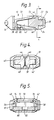
- Figure 1 is a cross-sectional view of a three-part buckle in accordance with the invention, with the mechanism in its release position and the tongues ejected, taken on the line 1 - 1 in Figure 2;
- Figures 2 and 3 are cross-sectional views taken on respective lines 2 - 2 and 3 - 3 in Figure 1;
- Figure 4 is a cross-sectional view taken on the line 4 - 4 in Figure 3;
- Figure 5 is a cross-sectional view taken on the line 5 - 5 in Figure 2;
- Figure 6 is a cross-sectional view, similar to Figure 1, but showing the buckle in its engaged condition;
- Figure 7 is a cross-sectional view taken on the line 7 - 7 in Figure 6;
- Figure 8 is a side view of the buckle shown in Figures 6 and 7 with one side of the buckle housing removed;
- Figures 9, 10 and 11 are cross-sectional views taken on respective lines 9 - 9, 10 - 10 and 11 - 11, in Figure 8 but with the buckle housing in place; and
- Figure 12 is a cross-sectional view, similar to Figure 6, of an alternative three-part buckle in accordance with the invention.
- Referring first to Figures 1 to 5, the buckle comprises a
buckle housing 10 and twotongues respective slots housing 10 is formed in twoparts parts - As can best be seen from Figure 1, the portions of the
tongues housing 10 have respective hook formations with latch-engaging surfaces engaging surfaces peg 34 which can be inserted into acorresponding recess 36 in theother tongue 14. - The
buckle housing 10 has twoopenings tongues openings central partition 38, behind which are located a pair oflatching levers upper stub axles lower stub axles housing 10. - As can be seen from Figures 1 and 3, the ends of the latching levers 40 and 42 nearer to the
openings tongues hook formations engaging surfaces tongues respective stub axles tongue buckle housing 10, tends to cause displacement of thecorresponding latching lever stub axles end portions latching lever respective flange ejector surface openings engaging surfaces tongues compression spring 68 so that theformations openings - A push-
button 70 is accommodated in an opening in the top of thehousing 10 and hinged thereto along oneedge 72 thereof.Flanges 74 and 76 (Figure 5) on the sides of the push-button 70 prevent it from moving above the top surface of thehousing 10. Opposite theedge 72, the push-button 70 has a downwardly extending formation 78 (Figure 2) which carries ablocking bar 80 extending under theends latching levers blocking bar 80 has acentral recess 82 in its upper surface (see Figures 3 and 5). However, with the latching levers 40 and 42 in the position illustrated in Figures 1 to 5, theends blocking bar 80 to hold the push-button in its depressed position, against the action of a leaf spring 84 (Figures 2, 7 and 11). - If the two
tongues peg 34 engages in therecess 36, and the ends of the tongues are inserted into theopenings engaging surfaces corresponding ejector surfaces latching levers latching lever 40 in the counter-clockwise direction and thelatching lever 42 in the clockwise direction so as to compress thespring 68 and bring theoffset ends latching levers recess 82 in theblocking bar 80, as shown in Figure 6. Theleaf spring 84 is then free to displace theblocking bar 80 and, with it, the push-button 70 upwardly, as shown in Figure 11 so that theends latching levers recess 82. Thetongues latching surfaces hook formations latching levers - If the push-
button 70 is now depressed, theblocking bar 80 is moved clear of theends latching levers spring 68. Abutment of theejector surfaces flanges engaging surfaces tongues housing 10. If movement of the latching levers 40 and 42 is impeded to such an extent that the force exerted by thespring 68 is insufficient, disengagement can be initiated by a force applied to eithertongue buckle housing 10, as described above. - If an attempt is made to insert only one of the tongues, for example the
tongue 12, into thehousing 10 without theother tongue 14, then thecorresponding latching lever 40 is displaced to the position shown in Figure 6 but theother latching lever 42 remains in the position shown in Figure 1, holding the push-button 70 in its depressed position. Consequently, as soon as thetongue 12 is released, it is ejected by the action of thespring 68. - The buckle illustrated in the drawings requires the two
tongues ends member 80 are set at a different angle thehook formations ejector surfaces - Figure 12 illustrates an alternative embodiment, in which the buckle comprises a
buckle housing 90 and twotongues respective slots tongues tongues hook formations buckle housing 90 has asingle opening 106 through which both tongues can be inserted simultaneously. A pair oflatching levers respective pivot axles hook formations hook formations tongues button 70 carries a blocking bar which differs from theblocking bar 80 of Figures 1 to 11 in that thecentral recess 82 therein is replaced by acentral projection 120 which engages betweenends latching levers
Claims (5)
- A buckle for a seat belt, comprising a buckle housing (10, 90) and two tongues (12, 14, 92, 94), the buckle housing (10, 90) containing a latching mechanism having a latching formation (40, 42, 108, 110) for each tongue (12, 14, 92, 94), the latching formations (40, 42, 108, 110) being arranged for angular movement about respective spaced mutually parallel pivot axes (44, 46, 112, 114) between locking positions in which they engage with respective latch-engaging surfaces (26, 28, 102, 104) on the tongues (12, 14, 92, 94) to prevent removal of the tongues (12, 14, 92, 94) from the buckle housing (10, 90) and a release position in which the tongues (12, 14, 92, 94) are removable from the buckle housing (10, 90), blocking means (80) being manually movable between a blocking position in which it obstructs movement of the latching formations (40, 42, 108, 110) from their locked positions to their release positions and a release position in which the latching formations (40, 42, 108, 110) are free to move between their locking positions and their release positions, each latching formation (40, 42, 108, 110) being shaped so that a force applied to a tongue (12, 14, 92, 94) in a direction to remove it from the buckle housing (10, 90) tends to cause displacement of the corresponding latching formation (40, 42, 108, 110) from its locking position to its release position, and each latching formation (40, 42, 108, 110) being arranged so that, when in its release position, it prevents movement of the blocking means (80) into its blocking position.
- A buckle according to claim 1, wherein the latching formations (40, 42, 108, 110) are biased towards their release positions by a spring (68) and each latching formation (40, 42, 108, 110) includes an ejector formation (64, 66) shaped to engage with its respective tongue (12, 14, 92, 94) so that movement of the latching formation (40, 42, 108, 110) from its locking position to its release position ejects the tongue, and insertion of the tongue (12, 14, 92, 94) moves the latching formation (40, 42, 108, 110) from its release position to its locked position.
- A buckle according to claim 1 or 2, wherein each latching formation comprises a latching lever (40, 42, 108, 110), mounted with its pivot axis (44, 46, 112, 114) at an intermediate position along its length, one end (52, 54) of each latching lever (40, 42, 108, 110) being arranged to engage with the corresponding tongue (12, 14, 92, 94) and the other end (56, 58) of each latching lever (40, 42, 108, 110) being arranged to engage with the blocking means (80).
- A buckle according to claim 3, wherein each latching lever (40, 42) carries an outwardly facing hook formation (52, 54) and each tongue (12, 14, 92, 94) engages between a respective latching lever (40, 42) and a respective part of the housing (10).
- A buckle according to claim 3, wherein each latching lever (108, 110) carries an inwardly facing hook formation (116, 118) and the tongues (92, 94) engage between the two latching levers (108, 110).
Applications Claiming Priority (2)
| Application Number | Priority Date | Filing Date | Title |
|---|---|---|---|
| GB8927190 | 1989-12-01 | ||
| GB898927190A GB8927190D0 (en) | 1989-12-01 | 1989-12-01 | Buckle for seat belt |
Publications (2)
| Publication Number | Publication Date |
|---|---|
| EP0436294A1 EP0436294A1 (en) | 1991-07-10 |
| EP0436294B1 true EP0436294B1 (en) | 1993-08-25 |
Family
ID=10667261
Family Applications (1)
| Application Number | Title | Priority Date | Filing Date |
|---|---|---|---|
| EP19900312773 Expired - Lifetime EP0436294B1 (en) | 1989-12-01 | 1990-11-23 | Buckle for seat belt |
Country Status (4)
| Country | Link |
|---|---|
| EP (1) | EP0436294B1 (en) |
| AU (1) | AU623294B2 (en) |
| DE (1) | DE69002929T2 (en) |
| GB (1) | GB8927190D0 (en) |
Family Cites Families (5)
| Publication number | Priority date | Publication date | Assignee | Title |
|---|---|---|---|---|
| US3523342A (en) * | 1968-01-22 | 1970-08-11 | John P Spires | Seat belt buckle latch |
| US3605210A (en) * | 1969-04-21 | 1971-09-20 | Jim Robbing Seat Belt Co | Side locking seat belt buckle |
| US3631571A (en) * | 1969-10-20 | 1972-01-04 | Robbins Seat Belt Co | Seat belt buckle assembly |
| AU1771270A (en) * | 1970-07-16 | 1972-01-20 | Cooldrive Consolidated Industries Proprietary Limited | Buckles for safety belts |
| SU1271777A1 (en) * | 1983-10-03 | 1986-11-23 | Производственное Объединение "Норма" | Clasp for safety belt of vehicle |
-
1989
- 1989-12-01 GB GB898927190A patent/GB8927190D0/en active Pending
-
1990
- 1990-11-23 DE DE90312773T patent/DE69002929T2/en not_active Expired - Fee Related
- 1990-11-23 EP EP19900312773 patent/EP0436294B1/en not_active Expired - Lifetime
- 1990-11-27 AU AU66988/90A patent/AU623294B2/en not_active Ceased
Also Published As
| Publication number | Publication date |
|---|---|
| DE69002929D1 (en) | 1993-09-30 |
| AU623294B2 (en) | 1992-05-07 |
| AU6698890A (en) | 1991-06-20 |
| GB8927190D0 (en) | 1990-01-31 |
| EP0436294A1 (en) | 1991-07-10 |
| DE69002929T2 (en) | 1994-01-13 |
Similar Documents
| Publication | Publication Date | Title |
|---|---|---|
| EP1224880B1 (en) | Security closing device for children seats and the like | |
| US4779315A (en) | Buckle with releasably interlockable members | |
| US4334341A (en) | Buckle for a safety belt | |
| US5267377A (en) | Buckle assembly | |
| US5588189A (en) | Buckle for vehicle seat belt system | |
| US3491414A (en) | Multitongue buckle with slidably mounted latch | |
| EP1018307B1 (en) | Buckle | |
| US4545097A (en) | Lock for a safety belt | |
| JPH02502886A (en) | End locking device for slide fasteners | |
| US5086548A (en) | Buckle device for seatbelt system | |
| AU626179B2 (en) | A coin lock for a trolley | |
| US5357658A (en) | Buckle apparatus | |
| WO1987003790A1 (en) | Buckle type fastener | |
| EP0098726A1 (en) | Safety belt buckles | |
| EP0673555B1 (en) | Electrical connector | |
| EP0301072A1 (en) | A safety belt buckle | |
| US4578659A (en) | Coupling system between an electromagnetic switch apparatus and an auxiliary contact block releasably mounted thereupon | |
| EP0204803A1 (en) | Buckle | |
| GB2057552A (en) | Safety belt buckle | |
| EP0758856B1 (en) | Buckle mechanism | |
| EP1025774A2 (en) | Seat belt buckle | |
| EP0436294A1 (en) | Buckle for seat belt | |
| EP0011275B1 (en) | Improvements in or relating to a buckle for a safety belt or harness | |
| US5421445A (en) | Coin lock for bar of supermarket cart | |
| US4642858A (en) | Buckle apparatus |
Legal Events
| Date | Code | Title | Description |
|---|---|---|---|
| PUAI | Public reference made under article 153(3) epc to a published international application that has entered the european phase |
Free format text: ORIGINAL CODE: 0009012 |
|
| AK | Designated contracting states |
Kind code of ref document: A1 Designated state(s): DE FR GB |
|
| 17P | Request for examination filed |
Effective date: 19910819 |
|
| 17Q | First examination report despatched |
Effective date: 19920630 |
|
| GRAA | (expected) grant |
Free format text: ORIGINAL CODE: 0009210 |
|
| AK | Designated contracting states |
Kind code of ref document: B1 Designated state(s): DE FR GB |
|
| ET | Fr: translation filed | ||
| REF | Corresponds to: |
Ref document number: 69002929 Country of ref document: DE Date of ref document: 19930930 |
|
| PLBE | No opposition filed within time limit |
Free format text: ORIGINAL CODE: 0009261 |
|
| STAA | Information on the status of an ep patent application or granted ep patent |
Free format text: STATUS: NO OPPOSITION FILED WITHIN TIME LIMIT |
|
| 26N | No opposition filed | ||
| PGFP | Annual fee paid to national office [announced via postgrant information from national office to epo] |
Ref country code: FR Payment date: 19961111 Year of fee payment: 7 |
|
| PG25 | Lapsed in a contracting state [announced via postgrant information from national office to epo] |
Ref country code: FR Free format text: THE PATENT HAS BEEN ANNULLED BY A DECISION OF A NATIONAL AUTHORITY Effective date: 19971130 |
|
| REG | Reference to a national code |
Ref country code: FR Ref legal event code: ST |
|
| PGFP | Annual fee paid to national office [announced via postgrant information from national office to epo] |
Ref country code: GB Payment date: 19991117 Year of fee payment: 10 |
|
| PGFP | Annual fee paid to national office [announced via postgrant information from national office to epo] |
Ref country code: DE Payment date: 19991129 Year of fee payment: 10 |
|
| PG25 | Lapsed in a contracting state [announced via postgrant information from national office to epo] |
Ref country code: GB Free format text: LAPSE BECAUSE OF NON-PAYMENT OF DUE FEES Effective date: 20001123 |
|
| GBPC | Gb: european patent ceased through non-payment of renewal fee |
Effective date: 20001123 |
|
| PG25 | Lapsed in a contracting state [announced via postgrant information from national office to epo] |
Ref country code: DE Free format text: LAPSE BECAUSE OF NON-PAYMENT OF DUE FEES Effective date: 20010801 |