EP0435874B1 - Pneumatic door operator having novel pneumatic actuator and lock - Google Patents
Pneumatic door operator having novel pneumatic actuator and lock Download PDFInfo
- Publication number
- EP0435874B1 EP0435874B1 EP19890908601 EP89908601A EP0435874B1 EP 0435874 B1 EP0435874 B1 EP 0435874B1 EP 19890908601 EP19890908601 EP 19890908601 EP 89908601 A EP89908601 A EP 89908601A EP 0435874 B1 EP0435874 B1 EP 0435874B1
- Authority
- EP
- European Patent Office
- Prior art keywords
- piston
- cylinder
- door
- motion
- internal
- Prior art date
- Legal status (The legal status is an assumption and is not a legal conclusion. Google has not performed a legal analysis and makes no representation as to the accuracy of the status listed.)
- Expired - Lifetime
Links
Images






Classifications
-
- E—FIXED CONSTRUCTIONS
- E05—LOCKS; KEYS; WINDOW OR DOOR FITTINGS; SAFES
- E05F—DEVICES FOR MOVING WINGS INTO OPEN OR CLOSED POSITION; CHECKS FOR WINGS; WING FITTINGS NOT OTHERWISE PROVIDED FOR, CONCERNED WITH THE FUNCTIONING OF THE WING
- E05F15/00—Power-operated mechanisms for wings
- E05F15/50—Power-operated mechanisms for wings using fluid-pressure actuators
- E05F15/56—Power-operated mechanisms for wings using fluid-pressure actuators for horizontally-sliding wings
- E05F15/565—Power-operated mechanisms for wings using fluid-pressure actuators for horizontally-sliding wings for railway-cars
-
- E—FIXED CONSTRUCTIONS
- E05—LOCKS; KEYS; WINDOW OR DOOR FITTINGS; SAFES
- E05F—DEVICES FOR MOVING WINGS INTO OPEN OR CLOSED POSITION; CHECKS FOR WINGS; WING FITTINGS NOT OTHERWISE PROVIDED FOR, CONCERNED WITH THE FUNCTIONING OF THE WING
- E05F15/00—Power-operated mechanisms for wings
- E05F15/60—Power-operated mechanisms for wings using electrical actuators
- E05F15/603—Power-operated mechanisms for wings using electrical actuators using rotary electromotors
- E05F15/632—Power-operated mechanisms for wings using electrical actuators using rotary electromotors for horizontally-sliding wings
- E05F15/643—Power-operated mechanisms for wings using electrical actuators using rotary electromotors for horizontally-sliding wings operated by flexible elongated pulling elements, e.g. belts, chains or cables
-
- E—FIXED CONSTRUCTIONS
- E05—LOCKS; KEYS; WINDOW OR DOOR FITTINGS; SAFES
- E05F—DEVICES FOR MOVING WINGS INTO OPEN OR CLOSED POSITION; CHECKS FOR WINGS; WING FITTINGS NOT OTHERWISE PROVIDED FOR, CONCERNED WITH THE FUNCTIONING OF THE WING
- E05F17/00—Special devices for shifting a plurality of wings operated simultaneously
- E05F17/004—Special devices for shifting a plurality of wings operated simultaneously for wings which abut when closed
-
- E—FIXED CONSTRUCTIONS
- E05—LOCKS; KEYS; WINDOW OR DOOR FITTINGS; SAFES
- E05Y—INDEXING SCHEME ASSOCIATED WITH SUBCLASSES E05D AND E05F, RELATING TO CONSTRUCTION ELEMENTS, ELECTRIC CONTROL, POWER SUPPLY, POWER SIGNAL OR TRANSMISSION, USER INTERFACES, MOUNTING OR COUPLING, DETAILS, ACCESSORIES, AUXILIARY OPERATIONS NOT OTHERWISE PROVIDED FOR, APPLICATION THEREOF
- E05Y2201/00—Constructional elements; Accessories therefor
- E05Y2201/20—Brakes; Disengaging means; Holders; Stops; Valves; Accessories therefor
- E05Y2201/218—Holders
-
- E—FIXED CONSTRUCTIONS
- E05—LOCKS; KEYS; WINDOW OR DOOR FITTINGS; SAFES
- E05Y—INDEXING SCHEME ASSOCIATED WITH SUBCLASSES E05D AND E05F, RELATING TO CONSTRUCTION ELEMENTS, ELECTRIC CONTROL, POWER SUPPLY, POWER SIGNAL OR TRANSMISSION, USER INTERFACES, MOUNTING OR COUPLING, DETAILS, ACCESSORIES, AUXILIARY OPERATIONS NOT OTHERWISE PROVIDED FOR, APPLICATION THEREOF
- E05Y2201/00—Constructional elements; Accessories therefor
- E05Y2201/20—Brakes; Disengaging means; Holders; Stops; Valves; Accessories therefor
- E05Y2201/218—Holders
- E05Y2201/22—Locks
-
- E—FIXED CONSTRUCTIONS
- E05—LOCKS; KEYS; WINDOW OR DOOR FITTINGS; SAFES
- E05Y—INDEXING SCHEME ASSOCIATED WITH SUBCLASSES E05D AND E05F, RELATING TO CONSTRUCTION ELEMENTS, ELECTRIC CONTROL, POWER SUPPLY, POWER SIGNAL OR TRANSMISSION, USER INTERFACES, MOUNTING OR COUPLING, DETAILS, ACCESSORIES, AUXILIARY OPERATIONS NOT OTHERWISE PROVIDED FOR, APPLICATION THEREOF
- E05Y2201/00—Constructional elements; Accessories therefor
- E05Y2201/20—Brakes; Disengaging means; Holders; Stops; Valves; Accessories therefor
- E05Y2201/23—Actuation thereof
- E05Y2201/232—Actuation thereof by automatically acting means
- E05Y2201/236—Actuation thereof by automatically acting means using force or torque
-
- E—FIXED CONSTRUCTIONS
- E05—LOCKS; KEYS; WINDOW OR DOOR FITTINGS; SAFES
- E05Y—INDEXING SCHEME ASSOCIATED WITH SUBCLASSES E05D AND E05F, RELATING TO CONSTRUCTION ELEMENTS, ELECTRIC CONTROL, POWER SUPPLY, POWER SIGNAL OR TRANSMISSION, USER INTERFACES, MOUNTING OR COUPLING, DETAILS, ACCESSORIES, AUXILIARY OPERATIONS NOT OTHERWISE PROVIDED FOR, APPLICATION THEREOF
- E05Y2201/00—Constructional elements; Accessories therefor
- E05Y2201/20—Brakes; Disengaging means; Holders; Stops; Valves; Accessories therefor
- E05Y2201/23—Actuation thereof
- E05Y2201/232—Actuation thereof by automatically acting means
- E05Y2201/236—Actuation thereof by automatically acting means using force or torque
- E05Y2201/238—Actuation thereof by automatically acting means using force or torque reaction force or torque
-
- E—FIXED CONSTRUCTIONS
- E05—LOCKS; KEYS; WINDOW OR DOOR FITTINGS; SAFES
- E05Y—INDEXING SCHEME ASSOCIATED WITH SUBCLASSES E05D AND E05F, RELATING TO CONSTRUCTION ELEMENTS, ELECTRIC CONTROL, POWER SUPPLY, POWER SIGNAL OR TRANSMISSION, USER INTERFACES, MOUNTING OR COUPLING, DETAILS, ACCESSORIES, AUXILIARY OPERATIONS NOT OTHERWISE PROVIDED FOR, APPLICATION THEREOF
- E05Y2201/00—Constructional elements; Accessories therefor
- E05Y2201/20—Brakes; Disengaging means; Holders; Stops; Valves; Accessories therefor
- E05Y2201/23—Actuation thereof
- E05Y2201/232—Actuation thereof by automatically acting means
- E05Y2201/24—Actuation thereof by automatically acting means using lost motion
-
- E—FIXED CONSTRUCTIONS
- E05—LOCKS; KEYS; WINDOW OR DOOR FITTINGS; SAFES
- E05Y—INDEXING SCHEME ASSOCIATED WITH SUBCLASSES E05D AND E05F, RELATING TO CONSTRUCTION ELEMENTS, ELECTRIC CONTROL, POWER SUPPLY, POWER SIGNAL OR TRANSMISSION, USER INTERFACES, MOUNTING OR COUPLING, DETAILS, ACCESSORIES, AUXILIARY OPERATIONS NOT OTHERWISE PROVIDED FOR, APPLICATION THEREOF
- E05Y2201/00—Constructional elements; Accessories therefor
- E05Y2201/20—Brakes; Disengaging means; Holders; Stops; Valves; Accessories therefor
- E05Y2201/23—Actuation thereof
- E05Y2201/244—Actuation thereof by manual operation
-
- E—FIXED CONSTRUCTIONS
- E05—LOCKS; KEYS; WINDOW OR DOOR FITTINGS; SAFES
- E05Y—INDEXING SCHEME ASSOCIATED WITH SUBCLASSES E05D AND E05F, RELATING TO CONSTRUCTION ELEMENTS, ELECTRIC CONTROL, POWER SUPPLY, POWER SIGNAL OR TRANSMISSION, USER INTERFACES, MOUNTING OR COUPLING, DETAILS, ACCESSORIES, AUXILIARY OPERATIONS NOT OTHERWISE PROVIDED FOR, APPLICATION THEREOF
- E05Y2201/00—Constructional elements; Accessories therefor
- E05Y2201/40—Motors; Magnets; Springs; Weights; Accessories therefor
- E05Y2201/43—Motors
- E05Y2201/434—Electromotors; Details thereof
-
- E—FIXED CONSTRUCTIONS
- E05—LOCKS; KEYS; WINDOW OR DOOR FITTINGS; SAFES
- E05Y—INDEXING SCHEME ASSOCIATED WITH SUBCLASSES E05D AND E05F, RELATING TO CONSTRUCTION ELEMENTS, ELECTRIC CONTROL, POWER SUPPLY, POWER SIGNAL OR TRANSMISSION, USER INTERFACES, MOUNTING OR COUPLING, DETAILS, ACCESSORIES, AUXILIARY OPERATIONS NOT OTHERWISE PROVIDED FOR, APPLICATION THEREOF
- E05Y2201/00—Constructional elements; Accessories therefor
- E05Y2201/40—Motors; Magnets; Springs; Weights; Accessories therefor
- E05Y2201/46—Magnets
-
- E—FIXED CONSTRUCTIONS
- E05—LOCKS; KEYS; WINDOW OR DOOR FITTINGS; SAFES
- E05Y—INDEXING SCHEME ASSOCIATED WITH SUBCLASSES E05D AND E05F, RELATING TO CONSTRUCTION ELEMENTS, ELECTRIC CONTROL, POWER SUPPLY, POWER SIGNAL OR TRANSMISSION, USER INTERFACES, MOUNTING OR COUPLING, DETAILS, ACCESSORIES, AUXILIARY OPERATIONS NOT OTHERWISE PROVIDED FOR, APPLICATION THEREOF
- E05Y2201/00—Constructional elements; Accessories therefor
- E05Y2201/60—Suspension or transmission members; Accessories therefor
- E05Y2201/604—Transmission members
-
- E—FIXED CONSTRUCTIONS
- E05—LOCKS; KEYS; WINDOW OR DOOR FITTINGS; SAFES
- E05Y—INDEXING SCHEME ASSOCIATED WITH SUBCLASSES E05D AND E05F, RELATING TO CONSTRUCTION ELEMENTS, ELECTRIC CONTROL, POWER SUPPLY, POWER SIGNAL OR TRANSMISSION, USER INTERFACES, MOUNTING OR COUPLING, DETAILS, ACCESSORIES, AUXILIARY OPERATIONS NOT OTHERWISE PROVIDED FOR, APPLICATION THEREOF
- E05Y2400/00—Electronic control; Electrical power; Power supply; Power or signal transmission; User interfaces
- E05Y2400/10—Electronic control
- E05Y2400/30—Electronic control of motors
- E05Y2400/3013—Electronic control of motors during manual wing operation
-
- E—FIXED CONSTRUCTIONS
- E05—LOCKS; KEYS; WINDOW OR DOOR FITTINGS; SAFES
- E05Y—INDEXING SCHEME ASSOCIATED WITH SUBCLASSES E05D AND E05F, RELATING TO CONSTRUCTION ELEMENTS, ELECTRIC CONTROL, POWER SUPPLY, POWER SIGNAL OR TRANSMISSION, USER INTERFACES, MOUNTING OR COUPLING, DETAILS, ACCESSORIES, AUXILIARY OPERATIONS NOT OTHERWISE PROVIDED FOR, APPLICATION THEREOF
- E05Y2800/00—Details, accessories and auxiliary operations not otherwise provided for
- E05Y2800/25—Emergency conditions
-
- E—FIXED CONSTRUCTIONS
- E05—LOCKS; KEYS; WINDOW OR DOOR FITTINGS; SAFES
- E05Y—INDEXING SCHEME ASSOCIATED WITH SUBCLASSES E05D AND E05F, RELATING TO CONSTRUCTION ELEMENTS, ELECTRIC CONTROL, POWER SUPPLY, POWER SIGNAL OR TRANSMISSION, USER INTERFACES, MOUNTING OR COUPLING, DETAILS, ACCESSORIES, AUXILIARY OPERATIONS NOT OTHERWISE PROVIDED FOR, APPLICATION THEREOF
- E05Y2800/00—Details, accessories and auxiliary operations not otherwise provided for
- E05Y2800/73—Multiple functions
-
- E—FIXED CONSTRUCTIONS
- E05—LOCKS; KEYS; WINDOW OR DOOR FITTINGS; SAFES
- E05Y—INDEXING SCHEME ASSOCIATED WITH SUBCLASSES E05D AND E05F, RELATING TO CONSTRUCTION ELEMENTS, ELECTRIC CONTROL, POWER SUPPLY, POWER SIGNAL OR TRANSMISSION, USER INTERFACES, MOUNTING OR COUPLING, DETAILS, ACCESSORIES, AUXILIARY OPERATIONS NOT OTHERWISE PROVIDED FOR, APPLICATION THEREOF
- E05Y2900/00—Application of doors, windows, wings or fittings thereof
- E05Y2900/50—Application of doors, windows, wings or fittings thereof for vehicles
- E05Y2900/51—Application of doors, windows, wings or fittings thereof for vehicles for railway cars or mass transit vehicles
-
- Y—GENERAL TAGGING OF NEW TECHNOLOGICAL DEVELOPMENTS; GENERAL TAGGING OF CROSS-SECTIONAL TECHNOLOGIES SPANNING OVER SEVERAL SECTIONS OF THE IPC; TECHNICAL SUBJECTS COVERED BY FORMER USPC CROSS-REFERENCE ART COLLECTIONS [XRACs] AND DIGESTS
- Y10—TECHNICAL SUBJECTS COVERED BY FORMER USPC
- Y10T—TECHNICAL SUBJECTS COVERED BY FORMER US CLASSIFICATION
- Y10T292/00—Closure fasteners
- Y10T292/08—Bolts
- Y10T292/096—Sliding
- Y10T292/1014—Operating means
- Y10T292/1021—Motor
Definitions
- This invention relates generally to automatic power door operators and more particularly concerns a pneumatic power door operator suitable for positioning overhead of the driven door when used on a mass transit vehicle.
- Pneumatic door operators have been utilized for a substantial period of time to open and close vehicular doors.
- Such operators employ long stroke pneumatic cylinders of conventional design, or pneumatic differential engines wherein rectilinear motion is converted to rotary motion through the use of rack and pinion gearing.
- Operators utilizing the long stroke piston require longitudinal overhead space approximately equal to twice the stroke or actuating movement of the cylinder.
- the relatively small rotary travel of the rack and pinion requires an extensive array of operating levers and/or force multiplying links in order to adequately operate a given door. Examples of these operators are contained in U.S. Patents 3,858,920, 3,916,567, 2,866,442 and 2,343,316.
- Recent mass transit vehicles are of streamlined design requiring construction methods which greatly reduce the available intra-structure spaces formerly utilized to house the operator. Reduced available space often does not permit installation of actuating and/or operating rods, cables, and/or other force transmitting devices.
- a further shortcoming of presently used pneumatic power door operators for transit vehicles arises from the requirement that vehicular doors be locked to prevent unauthorized exit or entry and safe operation of the car when in motion.
- door locking is sometimes achieved through "holding" pressure in the opposite side of a cylinder during vehicular operation.
- loss of pneumatic pressure with "pressure hold” operation can result in freewheeling doors and passenger hazards attendant thereto. Therefore, recent door equipment has for the most part required positive mechanical locks which do not depend on operating air pressure for maintaining the operated doors in a closed position.
- GB-A-2151697 discloses a power door operator as defined in the precharacterising part of claim 1 and using a pneumatic cylinder, with a mechanical latch for holding the door closed.
- the cylinder When the cylinder is pressurized in the door opening direction, the cylinder moves laterally (relative to the door; longitudinally relative to the cylinder) and this movement of the cylinder releases the mechanical latch.
- the present invention resides in a power door operator comprising a pneumatic cylinder having fluid sealed opposing ends and an internal fluid sealed piston slidable in the cylinder for reciprocal motion between the said ends from a first piston position to a second piston position, therein said motion defining a first internal piston travel distance and internal piston to cylinder end distances, first and second fluid-tight volumes defined by the piston inside the cylinder, fluid ports in the cylinder ends providing fluid communication between the said volumes and a pressurized fluid source and/or vents, and means for coupling the piston to a door for moving the door to open and close an opening e.g.
- the pneumatic cylinder is a rodless cylinder
- the internal piston being magnetic and being magnetically coupled to an external piston on the cylinder and mounted for motion along the cylinder thereby defining a second external piston travel distance
- the magnetic coupling between the internal and external pistons establishing a predetermined maximum inter-piston or breakaway force limiting the force that can be applied to the door by the door operator said interpiston force synchronising said external and internal piston motion and travel respectively for interpiston forces less than said breakaway value, whereby in use, if a force is exerted at the door exceeding that corresponding to the breakaway force of the door operator, for example by an unexpected obstruction or passenger in the door travel path, the internal and external pistons are uncoupled and the door is thereby uncoupled from the door operator.
- the invention overcomes essentially all of the above discussed spatial limitations and meets the operational requirements through the use of a rodless cylinder, thereby greatly reducing door overhead longitudinal space required for housing the operator.
- Rodless cylinder designs minimize longitudinal space to essentially that of the basic cylinder itself. The longitudinal space required is limited to essentially the movement of the operated door.
- Rodless cylinders are disclosed in US-A-3,779,401 and 4488477.
- a feature of the invention is the controlled force applied from the cylinder external piston to the operated door.
- Rodless cylinders utilize magnetic field coupling between a pneumatic piston internal of the cylinder and a magnetically coupled external piston.
- the maximum force that can be exerted on the external piston by the internal piston is termed "breakaway" force.
- the breakaway force is controlled to limit force applied to the operated door through mechanical coupling of the door and external piston. This construction minimizes applied door edge force allowing breakaway of the door when door movement is resisted due to objects or passengers in the door path, known as door obstructions.
- the internal and external pistons are coupled through magnetic attraction between the internal fluid-actuated piston, and the radially adjacent external piston.
- the external piston follows the internal piston movement due to inter-piston magnetically coupled force.
- the magnetic coupling forces are controlled and when the door operating force required exceeds the predetermined breakaway value, the internal and external pistons become uncoupled, allowing free movement of the door; recycling of the internal piston allows recoupling.
- Controlled breakaway force is advantageous in preventing excessive door edge force when unexpected objects in the door travel path obstruct door movement.
- Door breakaway allows the obstruction to be removed followed by re-coupling to complete door motion.
- the door operator preferably includes a mechanical lock which can be actuated or released by the pneumatic cylinder through the application of fluid pressure to the cylinder, and/or mechanically released in the case of loss of pressure and/or in an emergency.
- the said cylinder is mounted so that the cylinder can move laterally from a first to a second cylinder position in response to cylinder reaction forces on admission of pressurized fluid, admission of pressurized fluid to said cylinder for producing piston travel from the closed to the open position moving said cylinder laterally from said first to second position;
- a mechnical lock is operable by said cylinder motion for preventing door movement when when said piston is in the "closed” position in said cylinder and said cylinder is in said first position; and, means on said lock are responsive to said cylinder motion for releasing said lock when said cylinder moves from said first to second positions; whereby fluid admission moving said piston from its "closed” to its “open” position unlocks said articulating means and moves said door from closed to open.
- the piston In order to properly cushion the external cylinder stroke and minimize impact shocks between the moving door and its end of travel stops, the piston has an internal vent rod for controlling at first the operative exit air from the cylinder in the direction of piston travel, and a further controlled reduction in effective piston area as the piston approaches the end of the stroke.
- the cylinder has at least one central vent port in each end; an annular internal seal seat on said vent port; at least one flow control port in each said cylinder end; the internal piston has first and second opposing pressure responsive areas; a central coaxial vent rod is mounted in said piston, said rod having first and second ends and first and second pressure responsive areas on each rod end respectively, said first piston area and rod end area defining a pressure responsive differential piston, said differential piston further defining third and fourth effective pressure sensitive areas for piston locations in said cylinder between the piston end positions; the rod is located in said piston for limited motion and travel independent of said piston motion, said travel defining a rod sealing length; and seal means on said rod ends cooperate with said internal vent port seats for terminating vent port flow when piston travel to open or closed positions at either cylinder ends, said termination establishing a third and fourth opposite pressure responsive areas on said differential piston when said piston to cylinder end distances are less than said rod sealing lengths; whereby piston travel between the piston end positions is conditioned by fluid flow through said end cushion port and change in piston effective area
- This construction substantially reduces the energy absorption necessary when a rapidly moving door is decelerated at its open or closed position.
- the external piston portion of the aforementioned rodless cylinder drives a toothed belt coupled to horizontal cooperating pulleys mounted at either end of the door opening.
- the driven door or doors is appropriately attached to an adjacent portion of the toothed drive belt, resulting in door movement equivalent to the operating length of the cylinder.
- an additional bracket attached to the opposite side of the belt provides reversed door movement of the second door.
- Positive mechanical locking of the doors is achieved through releasably latching an adjacent portion of the belt to the car body frame. Release of the latch is accomplished through cotnrolled lateral motion of the entire cylinder assembly in the direction opposite to the door opening motion of the external cylinder.
- Door closing proceeds with air applied to the opposite side of the cylinder, moving the external cylinder in the opposite or closing direction.
- the latch As the cylinder is moved to the reaction position the latch approaches its mating hook, the latch is moved to a raised position by a wedge carried on the cylinder end, a position immediately above the aforesaid hook. In this location or position, a reduction in cylinder pressure allows the cylinder to return to its prior longitudinal or unpowered position, thereby dropping the latch on to its mating hook.
- the latch and hook achieve a positive mechanical lock of the operating belt and attendant locking of the operated doors.
- the mating seal and rod assembly act to close off first centrally located cylinder exhaust port. This forces air to exit through a substantially smaller second port thereby reducing piston speed.
- the pneumatic seal effected between the cylinder and seal rod end further acts to reduce the pressure effective piston area in the direction of motion so that in addition to the origice damping attained from the smaller relief port, a further reduction of piston speed is controllably achieved through proper selection of the rod diameters.
- FIG. 1 there is shown a preferred embodiment of the invention disclosed herein including a door operator and hanger assembly (1) operating concave sliding doors (2) and (3) for opening and closing an aperture in the wall (4) of a transit car.
- the door assemblies (2) and (3) are supported at their upper end by a door support rod (5) for the left hand door and an identical door support rod (6) for guiding the right hand door (3).
- Sliding doors (2) and (3) are supported and guided at their lower edge by a car floor or lower edge guide rail (7).
- the lower edge of either door (2) or (3) has a projection (8) which is partially contained in a carbody guide rail (7) for guiding door through lateral motion along the surface of the carbody (4).
- Anti-friction material (9) is interposed between the door projection or tongue (8) or guard rail (7).
- upper door guide or hanger (5a) Control of upper door movement is provided by upper door guide or hanger (5a).
- the upper door hangers (5a) are equipped at the interface between hanger and door support rods with anti-friction devices, typically a linear ball bushing.
- anti-friction devices typically a linear ball bushing.
- Spring (14a) controls force exerted on door panels by piston (11).
- the push back feature consists of a rod (14) surrounded by a compression spring (14a) abuttlng a cog belt adapter (15) for force transmittal to the door operating cog belt (16).
- the adapter (15) encircles the rod (14) and is contained between one end of the limited force push back spring (14a) and a U-shaped door force assembly bracket (15a).
- a toothed or cogged drive belt (16) is suspended between operating pulleys (16a) and (16b) mounted on the base of the operator disclosed and adjacent each end of the car door opening. Attached to opposite sides of the belt (16) are door operating brackets or arms (23) and (24). As best shown in Figures 4a and 4b, the operating brackets are arranged to operate the left and right hand doors (2) and (3) from opposite sides the belt (16).
- the power cylinder (10) is mounted above the car door opening space internal of the car body and is supported at either end by support brackets (17) and (18). Each end of the power cylinder is attached to its mounting bracket through lost motion slots (17a) and (18a) cooperating with retaining pins (19) and (19a). Extending from the right hand end of the power cylinder (10) is a lost motion force assembly (20) having a rod (21) with one end attached to the cylinder end (23), and its opposite end movably projecting through mounting bracket (22). The bracket (22) is fixed to the power door actuator base or other suitable portion of the door assembly structure.
- the reaction lock spring (20a) surrounds a major portion of the rod (21) and is retained between a stop nut adjacent the right hand cylinder end, and the inner face of the bracket (22).
- the projecting end of the rod (21) is threaded to permit adjustment of the compressed length of the spring (20a) providing control of the cylinder reaction force applied to the cylinder (10) as it traverses the slots (17a), and (18a) during operation of the reaction lock and unlock.
- a door lock hook Projecting from the right hand end of the U-shaped door force bracket (15a) is a door lock hook (30).
- a door lock hook cooperates with additional portions of a novel door lock disclosed herein which will be discussed in greater detail below.
- FIG. 13 supply air is introduced to a regulator 70 supplying regulated pressurized air to a two-position solenoid operated pneumatic valve 69 having open and closed solenoids 72 and 71 respectively. Air from the two position valves 69 is supplied for either opening or closing to the rodless cylinder 10 via inlet ports 13a and conducts 83 and 84.
- the rodless cylinder 10 is schematically shown to have an external piston 11 shown in Figure 13 in the closed position with a phantom location indicating an open position of the external piston.
- pneumatic limit switches 74 and 73 At either end of the cylinder 10 and arranged for contact with the external cylinder 11 in other open or closed position are pneumatic limit switches 74 and 73 respectively. Pneumatic limit switches 73 and 74 further equipped with exhaust silencers 76 and 78, and adjustable cushion vent or air throttling ports 75 and 77 respectively. As shown in Figure 14, the pneumatic limit switches are arranged to transfer a pneumatic path from each inlet 73a and 74a to one or two exit ports depending on the position of operating levers 79 and 80 as shown.
- open solenoid 72 on energization interconnects inlet pressure port P with solenoid valve of exit port 69b admitting air to the left hand and of cylinder 10 via conduit 83.
- energization of the open solenoid 72 connects the right hand port 13a of cylinder 10 with the right hand pneumatic switch 74 via conduits 84, ports 69a, and 69d, and conduct 81.
- right hand pneumatic switch 74 in its undepressed or unactuated position conducts exhaust air from conduit 81 through fitting 74a and air exit silencer 78.
- pneumatic limit switches 73 and 74 are such that prior to actuation by movement of external piston 11 of air cylinder 10, exit air is conducted or vented to the atmosphere via silencers 76 and 78.
- exit air passage is changed so that exhaust air exits via the adjustable or cushion orifice 75 or 77 respectively.
- the porting arrangement of open/close solenoid 69 insures the proper operating air inlet and exhaust air outlet circuitry.
- the rodless cylinder 10 has an internal fluid sealed piston 10a dividing the cylinder into pressure fluid sealed volumes 47 and 48.
- Internal of, and coaxial with, the piston 10a is an internal piston cushion rod 40, having somewhat enlarged head 42 at each end, and an intermediate shaft 41.
- the piston cushion rod 41 is mounted to slide in the piston 10a so that relative reciprocal motion between piston 10a and the cushion rod 40 is possible. Travel of rod 40 in the piston 10a is limited by the heads 42 at each end such that the maximum extent of the rod 40 and shaft 41, termed a rod ceiling length, is of a predetermined value. The significance of this rod ceiling length will be discussed below.
- sliding pressure seals 49 are interposed between the cusion rod shaft 41 and the piston 10a.
- the cylinder ends 10b contain internal chambers 10c in fluid communication with operating fluid ports 13, 13a.
- Each internal chamber has at one end a main cylinder vent port 46 and a reduced diameter cylinder cushion port 45.
- Each main cylinder vent 46 has on its internal surface an annular seal 50.
- Rod ends 42 in cooperation with seals 50 restrict cylinder air exit for predetermined end positions of a cushion rod 40 when cushion rod ens 42 abut the seals 50 as shown in Figures 11 and 12.
Landscapes
- Power-Operated Mechanisms For Wings (AREA)
- Lock And Its Accessories (AREA)
Abstract
Description
- This invention relates generally to automatic power door operators and more particularly concerns a pneumatic power door operator suitable for positioning overhead of the driven door when used on a mass transit vehicle.
- Pneumatic door operators have been utilized for a substantial period of time to open and close vehicular doors. Typically such operators employ long stroke pneumatic cylinders of conventional design, or pneumatic differential engines wherein rectilinear motion is converted to rotary motion through the use of rack and pinion gearing. Operators utilizing the long stroke piston require longitudinal overhead space approximately equal to twice the stroke or actuating movement of the cylinder. In operators using the differential engine, the relatively small rotary travel of the rack and pinion requires an extensive array of operating levers and/or force multiplying links in order to adequately operate a given door. Examples of these operators are contained in U.S. Patents 3,858,920, 3,916,567, 2,866,442 and 2,343,316.
- Recent mass transit vehicles are of streamlined design requiring construction methods which greatly reduce the available intra-structure spaces formerly utilized to house the operator. Reduced available space often does not permit installation of actuating and/or operating rods, cables, and/or other force transmitting devices.
- An important requirement is that doors should be openable in an emergency if power fails, and that damage or injury should not be caused if a closing door is obstructed by an unexpected object or passenger. Present mechanisms for these purposes are complex and cumbersome.
- A further shortcoming of presently used pneumatic power door operators for transit vehicles arises from the requirement that vehicular doors be locked to prevent unauthorized exit or entry and safe operation of the car when in motion. In the case of the aforementioned pneumatic operators of the long stroke cylinder or differential engine type, door locking is sometimes achieved through "holding" pressure in the opposite side of a cylinder during vehicular operation. As those skilled in the design and operation of transit vehicles will readily recognize, loss of pneumatic pressure with "pressure hold" operation can result in freewheeling doors and passenger hazards attendant thereto. Therefore, recent door equipment has for the most part required positive mechanical locks which do not depend on operating air pressure for maintaining the operated doors in a closed position.
- GB-A-2151697 discloses a power door operator as defined in the precharacterising part of
claim 1 and using a pneumatic cylinder, with a mechanical latch for holding the door closed. When the cylinder is pressurized in the door opening direction, the cylinder moves laterally (relative to the door; longitudinally relative to the cylinder) and this movement of the cylinder releases the mechanical latch. - The present invention resides in a power door operator comprising a pneumatic cylinder having fluid sealed opposing ends and an internal fluid sealed piston slidable in the cylinder for reciprocal motion between the said ends from a first piston position to a second piston position, therein said motion defining a first internal piston travel distance and internal piston to cylinder end distances, first and second fluid-tight volumes defined by the piston inside the cylinder, fluid ports in the cylinder ends providing fluid communication between the said volumes and a pressurized fluid source and/or vents, and means for coupling the piston to a door for moving the door to open and close an opening e.g. in a vehicle sidewall against door motion forces having friction, inertial, and obstruction components, characterized in that the pneumatic cylinder is a rodless cylinder, the internal piston being magnetic and being magnetically coupled to an external piston on the cylinder and mounted for motion along the cylinder thereby defining a second external piston travel distance, with means for mechanically coupling the external piston and the door for articulate motion therebetween, the magnetic coupling between the internal and external pistons establishing a predetermined maximum inter-piston or breakaway force limiting the force that can be applied to the door by the door operator said interpiston force synchronising said external and internal piston motion and travel respectively for interpiston forces less than said breakaway value, whereby in use, if a force is exerted at the door exceeding that corresponding to the breakaway force of the door operator, for example by an unexpected obstruction or passenger in the door travel path, the internal and external pistons are uncoupled and the door is thereby uncoupled from the door operator.
- The invention overcomes essentially all of the above discussed spatial limitations and meets the operational requirements through the use of a rodless cylinder, thereby greatly reducing door overhead longitudinal space required for housing the operator. Rodless cylinder designs minimize longitudinal space to essentially that of the basic cylinder itself. The longitudinal space required is limited to essentially the movement of the operated door. Rodless cylinders are disclosed in US-A-3,779,401 and 4488477.
- A feature of the invention is the controlled force applied from the cylinder external piston to the operated door. Rodless cylinders utilize magnetic field coupling between a pneumatic piston internal of the cylinder and a magnetically coupled external piston. The maximum force that can be exerted on the external piston by the internal piston is termed "breakaway" force. The breakaway force is controlled to limit force applied to the operated door through mechanical coupling of the door and external piston. This construction minimizes applied door edge force allowing breakaway of the door when door movement is resisted due to objects or passengers in the door path, known as door obstructions.
- Door motion and control are reestablished after breakaway by recycling the actuating piston in the cylinder.
- The internal and external pistons are coupled through magnetic attraction between the internal fluid-actuated piston, and the radially adjacent external piston. The external piston follows the internal piston movement due to inter-piston magnetically coupled force. The magnetic coupling forces are controlled and when the door operating force required exceeds the predetermined breakaway value, the internal and external pistons become uncoupled, allowing free movement of the door; recycling of the internal piston allows recoupling.
- Controlled breakaway force is advantageous in preventing excessive door edge force when unexpected objects in the door travel path obstruct door movement. Door breakaway allows the obstruction to be removed followed by re-coupling to complete door motion.
- In emergency situations, closed and locked doors can be opened by supplying a force exceeding the "breakaway" value.
- The door operator preferably includes a mechanical lock which can be actuated or released by the pneumatic cylinder through the application of fluid pressure to the cylinder, and/or mechanically released in the case of loss of pressure and/or in an emergency.
- Preferably the said cylinder is mounted so that the cylinder can move laterally from a first to a second cylinder position in response to cylinder reaction forces on admission of pressurized fluid, admission of pressurized fluid to said cylinder for producing piston travel from the closed to the open position moving said cylinder laterally from said first to second position; a mechnical lock is operable by said cylinder motion for preventing door movement when when said piston is in the "closed" position in said cylinder and said cylinder is in said first position; and, means on said lock are responsive to said cylinder motion for releasing said lock when said cylinder moves from said first to second positions; whereby fluid admission moving said piston from its "closed" to its "open" position unlocks said articulating means and moves said door from closed to open.
- In order to properly cushion the external cylinder stroke and minimize impact shocks between the moving door and its end of travel stops, the piston has an internal vent rod for controlling at first the operative exit air from the cylinder in the direction of piston travel, and a further controlled reduction in effective piston area as the piston approaches the end of the stroke.
- In a preferred construction the cylinder has at least one central vent port in each end; an annular internal seal seat on said vent port; at least one flow control port in each said cylinder end; the internal piston has first and second opposing pressure responsive areas; a central coaxial vent rod is mounted in said piston, said rod having first and second ends and first and second pressure responsive areas on each rod end respectively, said first piston area and rod end area defining a pressure responsive differential piston, said differential piston further defining third and fourth effective pressure sensitive areas for piston locations in said cylinder between the piston end positions; the rod is located in said piston for limited motion and travel independent of said piston motion, said travel defining a rod sealing length; and seal means on said rod ends cooperate with said internal vent port seats for terminating vent port flow when piston travel to open or closed positions at either cylinder ends, said termination establishing a third and fourth opposite pressure responsive areas on said differential piston when said piston to cylinder end distances are less than said rod sealing lengths; whereby piston travel between the piston end positions is conditioned by fluid flow through said end cushion port and change in piston effective area to said third and fourth areas.
- This construction substantially reduces the energy absorption necessary when a rapidly moving door is decelerated at its open or closed position.
- In this pneumatic power door operator, cushioning of door travel is provided through controlled escape of operating air, and change in effective piston area.
- In operation, the external piston portion of the aforementioned rodless cylinder drives a toothed belt coupled to horizontal cooperating pulleys mounted at either end of the door opening. The driven door or doors is appropriately attached to an adjacent portion of the toothed drive belt, resulting in door movement equivalent to the operating length of the cylinder. In the case of bi-parting double doors, an additional bracket attached to the opposite side of the belt provides reversed door movement of the second door.
- Positive mechanical locking of the doors is achieved through releasably latching an adjacent portion of the belt to the car body frame. Release of the latch is accomplished through cotnrolled lateral motion of the entire cylinder assembly in the direction opposite to the door opening motion of the external cylinder.
- Release operation of the lock occurs due to the reaction forces on the cylinder when pressurized air is admitted so as to drive the external cylinder in the opening direction. On entry of the actuating air, an initial and controlled motion due to door frictional and inertial resistance to motion operates to unlatch the door whereupon the cylinder is retained in the reaction position as the external cylinder moves in the opposite direction to complete door opening.
- Door closing proceeds with air applied to the opposite side of the cylinder, moving the external cylinder in the opposite or closing direction. As the cylinder is moved to the reaction position the latch approaches its mating hook, the latch is moved to a raised position by a wedge carried on the cylinder end, a position immediately above the aforesaid hook. In this location or position, a reduction in cylinder pressure allows the cylinder to return to its prior longitudinal or unpowered position, thereby dropping the latch on to its mating hook. The latch and hook achieve a positive mechanical lock of the operating belt and attendant locking of the operated doors.
- Cushioning of the internal pneumatic piston and door motion at the end of either opening or closing movement of the internal operating piston is accomplished through the use of the motion sensitive pressure sealed rod centrally located in the internal piston. Each end of the rod carries a seal which cooperates with a mating seal contained in each end of the cylinder.
- In operation as the piston and rod assembly approach either end of the cylinder, the mating seal and rod assembly act to close off first centrally located cylinder exhaust port. This forces air to exit through a substantially smaller second port thereby reducing piston speed. The pneumatic seal effected between the cylinder and seal rod end further acts to reduce the pressure effective piston area in the direction of motion so that in addition to the origice damping attained from the smaller relief port, a further reduction of piston speed is controllably achieved through proper selection of the rod diameters. Those skilled in the pneumatic art, will readily understand that the inclusion of a centrally located rod operable at a predetermined location of the piston results in a reduction in piston operating force through area reduction. Exposing a portion of the piston pressure sensitive area to external operating fluid pressure lower than that internal of the cylinder reduces the pressure sensitive piston area exposed to cylinder internal pressure. Action of the piston and central rod, rod end seals, and exhaust port seats establish a differential area piston wherein portions of the piston pressure sensitive area are exposed to and acted on by different fluid pressures.
- Other objects and advantages of the invention disclosed herein will become apparent upon reading the following detailed description and accompanying reference to the drawings in which:
- Figure 1 is a partial tear-away section of a typical sliding plug door of the type employing two bi-parting concave doors formed to match the convex outer surface of the vehicle.
- Figure 1a is a detailed section particularly snowing the lower door guide and support along
Section 1a-1a. - Figure 2 is a partial tear-away plan view of the actuator located overhead of the vehicular door opening, particularly showing the location of door actuating levers attached to the driven toothed belt, and push-back attachment to the operator external piston.
- Figure 3a is an additional partial tear-away view of the left hand door in a partially open position particularly showing the left hand lost motion mounting link of the actuating cylinder, and upper door support rods.
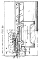
- Figure 3b is an additional partial tear-away view of the right hand driven door particularly showing right-hand the lost motion link and reaction force spring attached to the car frame.
- Figures 4a and 4b are detailed sections through the left hand and right hand doors particularly showing the utilization and location of the toothed belt pulleys, the upper door rod supports and hinged cover.
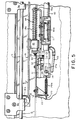
- Figure 5 is a further partial plan view of the right hand door member, particularly showing right-hand the lost motion link, reaction force spring, and door push back or door overtravel spring.
- Figure 6 is an isometric view of the mechanical lock, lost motion link of the operating cylinder, and location of the external piston attachment to the door operating cog belt, with lock components in positions immediately prior to a locked condition.
- Figure 7 is a detailed partial view of the actuating portion of the lost motion lock along Section 7-7 lines of Figure 6, showing lock components.
- Figure 8a, 8b and 8c are partial plan views of the latch look and actuating ramp portions of the positive mechanical lock with portions of the operator construction removed for clarity. In sequence, action of the lock in moving from unlatched to latched positions are shown.
- Figure 9 is a further perspective view of the mechanical lock as the actuating piston moves in the direction of locking with doors closed.
- Figure 9a is a detailed view of a portion of Figure 9 along the lines of
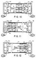
Section 9a-9a, showing the action of the reaction lock, and particularly showing the latch and lock just before engaging. Also shown is the opposite relative motion between the latch hook and actuating or external drive piston. - Figure 10 is a sectional view of the rodless cylinder without the external piston particularly showing the piston cushioning rod, inlet and outlet ports and piston operating air supply conducts and fittings..
- Figure 11 is an additional sectional view of the rodless cylinder of Figure 10, showing the internal piston and piston cushioning rod in a piston position at the cylinder left hand end.
- Figure 12 is a further sectional view of the rodless cylinder of Figure 10, showing the internal piston and piston cushioning rod in a piston cushioning configuration at the cylinder right hand end.
- Figure 13 is a simplified pneumatic circuit typically used to operate the door operator of the invention.
- Figure 14 is a semi-schematic diagram particularly showing fluid flow circuits of
pneumatic switches - With initial reference to Figure 1, there is shown a preferred embodiment of the invention disclosed herein including a door operator and hanger assembly (1) operating concave sliding doors (2) and (3) for opening and closing an aperture in the wall (4) of a transit car. The door assemblies (2) and (3) are supported at their upper end by a door support rod (5) for the left hand door and an identical door support rod (6) for guiding the right hand door (3). Sliding doors (2) and (3) are supported and guided at their lower edge by a car floor or lower edge guide rail (7). As shown in accompanying Figure 1a, the lower edge of either door (2) or (3) has a projection (8) which is partially contained in a carbody guide rail (7) for guiding door through lateral motion along the surface of the carbody (4). Anti-friction material (9) is interposed between the door projection or tongue (8) or guard rail (7).
- Control of upper door movement is provided by upper door guide or hanger (5a). As best seen in accompanying Figures (4a) and (4b) the upper door hangers (5a) are equipped at the interface between hanger and door support rods with anti-friction devices, typically a linear ball bushing. Those skilled in the art will readily understand that other types of anti-fraction interface can be used as well.
- Sliding or bi-parting movement of the doors (2) and (3) is achieved through use of the invention disclosed herein consisting of a rodless pneumatic cylinder (10) having an internal sliding pressure sensitive piston (10a) reference Figures 5, and 10. An external or operating piston (11) is magnetically coupled to the internal piston (10a) providing controlled force for linear travel of the external piston (11) along the outer periphery of the piston (10) when air pressure is introduced the cylinder (11) on either side of the piston (10a). Typically air is introduced at either end of the cylinder via conducts (13) and (13a). Returning to Figures 2 and 5, attached to the external piston (11) is a door force bracket assembly (12) incorporating a lost motion or push back feature providing relative motion between door panels and the drive belt (16) and external piston (11). Spring (14a) controls force exerted on door panels by piston (11). The push back feature consists of a rod (14) surrounded by a compression spring (14a) abuttlng a cog belt adapter (15) for force transmittal to the door operating cog belt (16). The adapter (15) encircles the rod (14) and is contained between one end of the limited force push back spring (14a) and a U-shaped door force assembly bracket (15a).
- As shown in Figures 2, 3a, and 3b, a toothed or cogged drive belt (16) is suspended between operating pulleys (16a) and (16b) mounted on the base of the operator disclosed and adjacent each end of the car door opening. Attached to opposite sides of the belt (16) are door operating brackets or arms (23) and (24). As best shown in Figures 4a and 4b, the operating brackets are arranged to operate the left and right hand doors (2) and (3) from opposite sides the belt (16).
- The power cylinder (10) is mounted above the car door opening space internal of the car body and is supported at either end by support brackets (17) and (18). Each end of the power cylinder is attached to its mounting bracket through lost motion slots (17a) and (18a) cooperating with retaining pins (19) and (19a). Extending from the right hand end of the power cylinder (10) is a lost motion force assembly (20) having a rod (21) with one end attached to the cylinder end (23), and its opposite end movably projecting through mounting bracket (22). The bracket (22) is fixed to the power door actuator base or other suitable portion of the door assembly structure. The reaction lock spring (20a) surrounds a major portion of the rod (21) and is retained between a stop nut adjacent the right hand cylinder end, and the inner face of the bracket (22). The projecting end of the rod (21) is threaded to permit adjustment of the compressed length of the spring (20a) providing control of the cylinder reaction force applied to the cylinder (10) as it traverses the slots (17a), and (18a) during operation of the reaction lock and unlock.
- Projecting from the right hand end of the U-shaped door force bracket (15a) is a door lock hook (30). With particular reference to Figures 6, 8a, 8b, 8c, 9 and 9a, a door lock hook cooperates with additional portions of a novel door lock disclosed herein which will be discussed in greater detail below.
- Power cylinder motion due to cylinder force reaction as described above and the door locking feature will be further discussed in substantial detail below.
- Pneumatic operation of the door operator invention is typically accomplished through the simplified circuit of Figure 13. As those skilled in the pneumatic arts will readily understand that many other variations and adaptations of the disclosed pneumatic circuitry can be utilized, applicant's disclosure is non-limiting, and only included as an adjunct to the invention disclosed herein. Turning now to Figure 13, supply air is introduced to a regulator 70 supplying regulated pressurized air to a two-position solenoid operated
pneumatic valve 69 having open andclosed solenoids 72 and 71 respectively. Air from the twoposition valves 69 is supplied for either opening or closing to therodless cylinder 10 viainlet ports 13a and conducts 83 and 84. Therodless cylinder 10 is schematically shown to have anexternal piston 11 shown in Figure 13 in the closed position with a phantom location indicating an open position of the external piston. - At either end of the
cylinder 10 and arranged for contact with theexternal cylinder 11 in other open or closed position arepneumatic limit switches exhaust silencers air throttling ports inlet - In operation, with particular reference to Figure 13, wherein the external cylinder is shown in a closed position, the preceding or closing operation was accomplished by energizing
solenoid 71 whereupon the two-positionpneumatic switch 69 controlled pressure operating air to enter the right hand end of thecylinder 10 viainlet port 13a, conduit 84, andvalve exit port 69a. Also, in the movement of the air cylinderinternal piston 10a from open to closed followed by theexternal piston 11, operating exit air was vented via lefthand exit port 13a,conduit 83, and solenoidcylinder exit port 69c. Vented air further passed through external pistonpneumatic limit switch 73 viaconduit 82 andadjustable cushion orifice 75. - For the reverse operation, i.e., motion of
external cylinder 11 andinternal cylinder 10a from closed to open, open solenoid 72 on energization, interconnects inlet pressure port P with solenoid valve ofexit port 69b admitting air to the left hand and ofcylinder 10 viaconduit 83. Simultaneously, energization of the open solenoid 72 connects theright hand port 13a ofcylinder 10 with the righthand pneumatic switch 74 via conduits 84,ports conduct 81. As shown righthand pneumatic switch 74 in its undepressed or unactuated position conducts exhaust air fromconduit 81 through fitting 74a andair exit silencer 78. - The action of
pneumatic limit switches external piston 11 ofair cylinder 10, exit air is conducted or vented to the atmosphere viasilencers external piston 11, such that the operating levers 79 or 80 are depressed, exit air passage is changed so that exhaust air exits via the adjustable orcushion orifice external piston 11, between open and closed positions, i.e., when both operating levers ofswitches close solenoid 69 insures the proper operating air inlet and exhaust air outlet circuitry. - The above pneumatic circuit is only typical and may or may not be used in conjunction with a feature disclosed in Figures 10, 11, and 12 herein, and is included only to provide a complete operating description of one embodiment of the invention disclosed.
- Operation of the reaction lock is best understood with particular reference to Figures 5, 6, 7, 8 9, and 9a. In operation, beginning with the doors in a closed position as shown in Figure 1, with no air pressure in other side of the cylinder (10). Under these conditions the position of cylinder (10) as shown in Figure 5 and the door latch and hook assembly would be engaged as indicated in Figure 8c. It should be noted that at all times when pressure is absent from either side of cylinder (10), the reaction spring (20a) will position the cylinder lost motion retaining pin (19) at the left hand edge of the slot (17a) with pin (19a) positioned in slot (18a) as shown in Figure 2. The latch assembly (31) and hook (30) will be in the engaged position as shown in Figure 8c, thus preventing movement of the belt (16) thereby looking both doors (2) and (3) in position shown in Figure 1.
- On admission of air to the left hand end of cylinder (10) through air inlet (13), forces generated due to the difference in pressure on internal piston (10a) (Reference Figure 5), will produce an equal and opposite force on the cylinder (10), moving the cylinder end so as to position the pin (19) at the right hand end of slot (17a). With reference to Figure 6, left hand movement of the cylinder (10), external piston (11) and right-hand cylinder end (23) moves the door unlock wedge (33) to the left (Reference Figure 6), thereby contacting door latch roller (32), rotating the latch assembly (31) around its pin support (31a) against latching force exerted by latch hold down spring (34) thus placing the latch elements (31), (32), (33) and (30) as shown in Figures 9 and 9a. Reaction movement of the cylinder (10) has therefore unlocked the latching members of the lock assemblies.
- On contact of the lost motion pin (19) with the right hand edge of the slot (17a) along with unlocking the latch members, external cylinder (11) moves the door force bracket belt adapter (15) in the right hand direction (Reference Figures 5, and 3b). Movement of the belt (16) around pulleys (16a) and (16b) moves door operating brackets (23) and (24) so as to move door (2) in a left hand direction and door (3) in the right hand direction as shown in Figures 3a and 3b.
- Force is applied to the belt (16) by external piston (11) throught the push back and force limiting assembly (12) (Reference Figure 2). As the door force assembly bracket (15a) moves to the rights, spring (14a) is compressed as the door force belt adapter (15) moves left-ward along the door force adapter shaft (14) thereby compressing spring (14a) to some extent. The spring rate of (14a) is chosen so as to allow a predetermined amount of relative motion between the bracket (15a) and belt (16) thereby allowing a predetermined amount of relative motion of the doors (2) and (3) through actuating brackets (23) and (24).
- Movement of the doors (2) and (3) in the opening direction proceeds until the internal piston (10a) approaches the left hand end of the cylinder (10) (Reference Figures 13, 14 and the above description of pneumatic operating system 60).
- Operation of an alternative rodless cylinder which can be used in a door operator of the invention is best understood by reference to Figures 10, 11, and 12. As this aspect of the invention involves only the internal cylinder and associated operating air ports, Figures 10, 11 and 12 for the sake of clairty show only the operating components involved.
- The
rodless cylinder 10 has an internal fluid sealedpiston 10a dividing the cylinder into pressure fluid sealedvolumes piston 10a is an internalpiston cushion rod 40, having somewhatenlarged head 42 at each end, and anintermediate shaft 41. Thepiston cushion rod 41 is mounted to slide in thepiston 10a so that relative reciprocal motion betweenpiston 10a and thecushion rod 40 is possible. Travel ofrod 40 in thepiston 10a is limited by theheads 42 at each end such that the maximum extent of therod 40 andshaft 41, termed a rod ceiling length, is of a predetermined value. The significance of this rod ceiling length will be discussed below. In order to ensure the pressure integrity ofchembers cusion rod shaft 41 and thepiston 10a. - The cylinder ends 10b contain
internal chambers 10c in fluid communication with operatingfluid ports cylinder vent port 46 and a reduced diametercylinder cushion port 45. Eachmain cylinder vent 46 has on its internal surface anannular seal 50. Rod ends 42 in cooperation withseals 50 restrict cylinder air exit for predetermined end positions of acushion rod 40 whencushion rod ens 42 abut theseals 50 as shown in Figures 11 and 12. - In operation, during the movement of
internal piston 10a from either end to the other, i.e., from opened to closed or closed to open positions of the operated door, relative positions ofpiston 10a andpiston cushion rod 40 are such that the effective pressure sensing ar3eas are the sum of the cross section area of pistoncushion rod shaft 41 and the annular area ofpiston 10a. These are shown on Figure 10 as 10d. Similarly the effective pressure sensing areas of thepiston cushion rod 40 are shown on Figure 10 as 40a. - During piston travel, from ether end to the other, when the extended portion of piston
cushion rod shaft 41 is equal to or less than the distance between that face ofpiston 10a, and the adjacent cylinder end, end 42 of thecushion rod 40 abuts the mainvent orifice seal 50 thereby restricting exhaust air flow from thechamber 47 to flow through cushion inport 45. Contact of thecushion rod end 42 and seal 50 effectively removes the effective pressure sensing area ofrod 41 i.e., 40a, from the force producing sum of the opposite side ofpiston 10a, that is the effective pressure sensing area ofpiston 10a becomes the difference betweenarea piston 10a and conditioning travel of 10a and its associated movement ofexternal piston 11 and ultimately the enclosure speeds and force of operateddoors internal piston 10a andcushion rod 40 can be utilized in both opening and closing modes of the doors controlled, any combination of the disclosed differential area piston and its conditioning of door movement and other pneumatic control systems will be seen by those skilled in the art. Those skilled in the art will also readily see that the reverse operation, i.e., piston travel from left to right in Figure 10 will proceed in an identical manner.
Claims (4)
- A power door operator comprising a pneumatic cylinder (10) having opposing fluid sealed ends and an internal fluid sealed piston (10a) slidable in the cylinder for reciprocal motion between the said ends from a first piston position to a second piston position therein, said motion defining a first internal piston travel distance and internal piston to cylinder end distances, first and second fluid-tight volumes (47, 48) defined by the piston (10a) inside the cylinder, fluid ports (46) in the cylinder ends providing fluid communication between the said volumes and a pressurized fluid source and/or vents, and means (11, 16) for coupling the piston to a door for moving the door to open and close an opening e.g. in a vehicle sidewall against door motion forces having friction, inertial, and obstruction components,
characterized in that the pneumatic cylinder is a rodless cylinder, the internal piston (10a) being magnetic and being magnetically coupled to an external piston (11) on the cylinder mounted for motion along the cylinder thereby defining a second external piston travel distance, with means (16) for mechanically coupling the external piston (11) and the door for articulate motion therebetween, the magnetic coupling between the internal and external pistons establishing a predetermined maximum inter-piston or breakaway force limiting the force that can be applied to the door by the door operator said interpiston force synchronising said external and internal piston motion and travel respectively for interpiston forces less than said breakaway value, whereby in use, if a force is exerted at the door exceeding that corresponding to the breakaway force of the door operator, for example by an unexpected obstruction or passenger in the door travel path, the internal and external pistons are uncoupled and the door is thereby uncoupled by the door operator. - The power door operator claimed in claim 1 in which the internal piston has first and second end positions in the cylinder, piston travel from said first to second positions being operative for moving said door from an open to a closed position, and piston travel from said second position to said first position, adjacent the opposite cylinder end, being operative for moving said door from closed to open,
the door operator further including means (17, 18) mounting said cylinder (10) so that the cylinder can move laterally from a first to a second cylinder position in response to cylinder reaction forces on admission of pressurized fluid,
said admission of pressurized fluid to said cylinder for producing said piston travel from said second to first position moving said cylinder laterally from said first to second position;
means (17a, 19; 18a, 19a) limiting said cylinder lateral motion to predetermined distance against predetermined force;
a mechanical lock (30-33) operable by said cylinder motion for locking said articulating means (16) and preventing door movement when said piston is in the second position in said cylinder and said cylinder is in said first position; and,
means (33) on said lock responsive to said cylinder motion for releasing said lock when said cylinder moves from said first to second positions;
whereby fluid admission moving said piston from its second to first position unlocks said articulating means and moves said door from closed to open. - The door operator of Claim 1 or 2, in which the cylinder (10) has
at least one central vent port (46) in each end;
an annular internal seal seat (50) on said vent port;
and at least one flow control port (45) in each said cylinder end;
the internal piston (10a) has first and second opposing pressure responsive areas (10d);
a central coaxial vent rod (40) in said piston has first and second ends (42) and first and second pressure responsive areas (40a) on each rod end respectively, said first piston area and rod end area defining a pressure responsive differential piston, said differential piston further defining third and fourth effective pressure sensitive areas for piston locations in said cylinder between, the piston end positions;
said rod (40) is located in said piston for limited motion and travel independent of said piston motion, said travel defining a rod sealing length;
and seal means are provided on said rod ends, cooperating with said internal vent port seats (50) for terminating vent port flow when piston travel to open or closed positions at either cylinder ends, said termination establishing a third and fourth opposite pressure responsive areas on said differential piston when said piston to cylinder end distances are less than said rod sealing length;
whereby piston travel from one end position to another end position is conditioned by fluid flow through said end cushion port and change in piston effective area to said third and fourth areas. - The door operator of claim 1, 2 or 3 wherein said mechanical coupling means between said external piston and door is a continuous toothed belt (16).
Priority Applications (1)
| Application Number | Priority Date | Filing Date | Title |
|---|---|---|---|
| AT89908601T ATE123325T1 (en) | 1989-06-28 | 1989-06-28 | PNEUMATIC DOOR ACTUATOR WITH NEW PNEUMATIC RELEASE AND CLOSING DEVICE. |
Applications Claiming Priority (2)
| Application Number | Priority Date | Filing Date | Title |
|---|---|---|---|
| US07/167,221 US4901474A (en) | 1988-03-11 | 1988-03-11 | Pneumatic door operator having novel pneumatic actuator and lock |
| PCT/US1989/002866 WO1991000407A1 (en) | 1988-03-11 | 1989-06-28 | Pneumatic door operator having novel pneumatic actuator and lock |
Publications (3)
| Publication Number | Publication Date |
|---|---|
| EP0435874A1 EP0435874A1 (en) | 1991-07-10 |
| EP0435874A4 EP0435874A4 (en) | 1991-11-27 |
| EP0435874B1 true EP0435874B1 (en) | 1995-05-31 |
Family
ID=22606451
Family Applications (1)
| Application Number | Title | Priority Date | Filing Date |
|---|---|---|---|
| EP19890908601 Expired - Lifetime EP0435874B1 (en) | 1988-03-11 | 1989-06-28 | Pneumatic door operator having novel pneumatic actuator and lock |
Country Status (6)
| Country | Link |
|---|---|
| US (1) | US4901474A (en) |
| EP (1) | EP0435874B1 (en) |
| JP (1) | JP2909594B2 (en) |
| CA (1) | CA1321219C (en) |
| DE (1) | DE68922907D1 (en) |
| WO (1) | WO1991000407A1 (en) |
Families Citing this family (46)
| Publication number | Priority date | Publication date | Assignee | Title |
|---|---|---|---|---|
| US5148631A (en) * | 1988-03-11 | 1992-09-22 | Mark Iv Transportation Products Corporation | Pneumatic door operator having pneumatic actuator and lock |
| US5477030A (en) * | 1994-04-18 | 1995-12-19 | Robertshaw Controls Company | Cooking apparatus, latching construction therefor and methods of making the same |
| US5440103A (en) * | 1994-05-27 | 1995-08-08 | Robertshaw Controls Company | Cooking apparatus, latching construction therefor and methods of making the same |
| US5493099A (en) * | 1994-12-28 | 1996-02-20 | Robertshaw Controls Company | Cooking apparatus, latching construction therefor and methods of making the same |
| FR2729130A1 (en) * | 1995-01-11 | 1996-07-12 | Otis Elevator Co | Support for hanging elevator cables to prevent lateral movement |
| JPH10509488A (en) * | 1995-09-20 | 1998-09-14 | フエスト コマンデイートゲゼルシヤフト | Locking device for pneumatic door |
| US6009668A (en) * | 1996-01-22 | 2000-01-04 | Westinghouse Air Brake Company | Power door operator having rotary drive and drive operated direct panel lock |
| US5927015A (en) * | 1996-11-07 | 1999-07-27 | Vapor Canada, Inc. | Powered door drive system and lock |
| US6141908A (en) * | 1998-08-13 | 2000-11-07 | Westinghouse Air Brake Company | Transit vehicle door system |
| US6446389B1 (en) * | 2000-04-14 | 2002-09-10 | Westinghouse Air Brake Technologies Corporation | Tandem sliding door operator |
| AT411283B (en) * | 2000-03-16 | 2003-11-25 | Knorr Bremse Gmbh | CONTROLLING THE MOVEMENT OF A SLIDING OR Pivoting sliding door in your closing area |
| FR2822185B1 (en) * | 2001-03-19 | 2003-08-15 | Faiveley Transport | MOTORIZED DOOR LOCKING DEVICE WITH REDUCED DIMENSIONS |
| US6662501B2 (en) * | 2001-05-07 | 2003-12-16 | Westinghouse Air Brake Technologies Corporation | Emergency release mechanism for electrical bus door |
| US6712406B2 (en) * | 2002-08-28 | 2004-03-30 | Westubggiyse Aur Brake Technologies Corporation | Lock latch mechanism for transit vehicle door system |
| AU2003265918A1 (en) * | 2002-09-03 | 2004-03-29 | Rytec Corporation | Dual overhead track for a sliding door |
| JP4072680B2 (en) * | 2003-02-26 | 2008-04-09 | 富士電機システムズ株式会社 | Door equipment |
| US6803733B1 (en) * | 2003-04-08 | 2004-10-12 | General Motors Corporation | Pillar-mounted power door lock and power window system for a vehicle |
| DE20307840U1 (en) * | 2003-05-20 | 2003-07-24 | Gebr. Bode GmbH & Co. KG, 34123 Kassel | Emergency unlocking device on a sliding door for vehicles, in particular public transport vehicles |
| US7219950B2 (en) * | 2004-03-16 | 2007-05-22 | Utilimaster Corporation | Sliding door assembly |
| US7228804B2 (en) * | 2004-04-21 | 2007-06-12 | Wabtec Holding Corp. | Door system for transit vehicle utilizing compression lock arrangement |
| KR100759713B1 (en) * | 2005-06-24 | 2007-10-04 | 이철희 | Fire door automatic closing device and system. |
| KR100759712B1 (en) * | 2005-06-24 | 2007-09-18 | 이철희 | Automatic close system which shuts down several fire doors simultaneously |
| WO2008124816A1 (en) * | 2007-04-10 | 2008-10-16 | Wabtec Holding Corp. | Cushioning system for pneumatic cylinder of differential engine |
| US20110041408A1 (en) * | 2007-10-26 | 2011-02-24 | Lopez Saez Alberto | System for the translation and locking operation of sliding doors |
| IL196690A0 (en) * | 2008-05-29 | 2011-08-01 | Plasan Sasa Ltd | Interchangeable door |
| SG174936A1 (en) * | 2009-03-24 | 2011-11-28 | Somyung Co Ltd | Electric door-locking apparatus, and electric door comprising same |
| KR101034589B1 (en) * | 2009-04-02 | 2011-05-11 | (주)보체스 | Electric door lock |
| US8959836B2 (en) * | 2011-04-07 | 2015-02-24 | Hydra DoorCo LLC | Sliding security door |
| CN102330533A (en) * | 2011-07-06 | 2012-01-25 | 辽宁圣维机电科技股份有限公司 | Pneumatic safety underground shielding door |
| US8998278B2 (en) * | 2011-07-11 | 2015-04-07 | Strattec Power Access Llc | Striker concealment mechanism and method |
| CN103781982B (en) * | 2011-09-09 | 2016-05-04 | 纳博特斯克有限公司 | Opening and closing device with locking function |
| JP6209905B2 (en) * | 2013-09-04 | 2017-10-11 | 富士電機株式会社 | Door control device |
| JP6576628B2 (en) * | 2014-10-31 | 2019-09-18 | ナブテスコ株式会社 | Lock device for vehicle door |
| RU2578925C1 (en) * | 2014-12-29 | 2016-03-27 | Общество с ограниченной ответственностью "ФЕСТО-РФ" (ООО "ФЕСТО-РФ") | Pneumatic actuator for sliding doors of vehicle |
| JP6530612B2 (en) * | 2015-02-10 | 2019-06-12 | ナブテスコ株式会社 | Door hanging device |
| FR3061227B1 (en) * | 2016-12-27 | 2019-11-29 | Faiveley Transport Tours | MULTIFUNCTIONAL MODULE FOR SLIDING LOUVOYANTE DOOR, AND VEHICLE THUS EQUIPPED |
| US11351277B2 (en) * | 2017-06-27 | 2022-06-07 | American Sterilizer Company | Self-adjusting damper based linear alignment system |
| US10954974B2 (en) | 2017-10-20 | 2021-03-23 | Hamilton Sunstrand Corporation | Actuator assembly with lost motion device |
| US10830365B2 (en) | 2017-10-26 | 2020-11-10 | Hamilton Sundstrand Corporation | Bi-directional inline check valve |
| WO2019087370A1 (en) * | 2017-11-02 | 2019-05-09 | 富士電機株式会社 | Door opening/closing device |
| DE202017106685U1 (en) * | 2017-11-06 | 2019-02-19 | Gebr. Bode Gmbh & Co. Kg | Door drive with locking device |
| US10724278B2 (en) * | 2018-02-09 | 2020-07-28 | Westinghouse Air Brake Technologies Corporation | Secondary retention device for bi-parting doors |
| DE202018106718U1 (en) * | 2018-11-26 | 2020-03-04 | Gebr. Bode Gmbh & Co. Kg | Door arrangement |
| US11885160B2 (en) * | 2019-11-01 | 2024-01-30 | Westinghouse Air Brake Technologies Corporation | Sliding door locking device |
| ES3042784T3 (en) * | 2019-12-04 | 2025-11-24 | Dormakaba Deutschland Gmbh | Drive unit for a sliding door |
| US20220081954A1 (en) * | 2020-09-11 | 2022-03-17 | International Truck Intellectual Property Company, Llc | Door actuator |
Family Cites Families (12)
| Publication number | Priority date | Publication date | Assignee | Title |
|---|---|---|---|---|
| US2343316A (en) * | 1943-03-30 | 1944-03-07 | Nat Pneumatic Co | Door operator |
| US3727349A (en) * | 1970-09-21 | 1973-04-17 | Rohr Industries Inc | Suspension mechanism for sliding doors |
| GB1317105A (en) * | 1971-02-18 | 1973-05-16 | Marine Eng Co Stockport Ltd | Fluid operated device for moving articles |
| DE2359484A1 (en) * | 1972-12-01 | 1974-06-06 | Westinghouse Brake & Signal | MULTI-PART SLIDING DOOR DEVICE |
| US3799401A (en) * | 1972-12-05 | 1974-03-26 | Xerox Corp | Silicone oil capacity control using polyurethane belt |
| US3858920A (en) * | 1973-05-31 | 1975-01-07 | Monocab Inc | Vehicle door positioning and locking assembly |
| JPS5876804U (en) * | 1981-11-19 | 1983-05-24 | 焼結金属工業株式会社 | rodless cylinder |
| JPS58152907A (en) * | 1982-03-05 | 1983-09-10 | Ckd Corp | Air cylinder |
| JPS5996270U (en) * | 1982-12-20 | 1984-06-29 | 株式会社ナブコ | Drive device for draw door |
| GB2151697B (en) * | 1983-12-22 | 1987-03-04 | Peters Plc Ltd | Pneumatic door actuator assembly |
| GB2165004B (en) * | 1984-09-27 | 1987-11-11 | British Nuclear Fuels Plc | Improvements in or relating to fluid operated devices for moving articles |
| JPH0419214Y2 (en) * | 1986-01-21 | 1992-04-30 |
-
1988
- 1988-03-11 US US07/167,221 patent/US4901474A/en not_active Expired - Lifetime
-
1989
- 1989-03-09 CA CA000593281A patent/CA1321219C/en not_active Expired - Fee Related
- 1989-06-28 JP JP1508020A patent/JP2909594B2/en not_active Expired - Fee Related
- 1989-06-28 DE DE68922907T patent/DE68922907D1/en not_active Expired - Lifetime
- 1989-06-28 WO PCT/US1989/002866 patent/WO1991000407A1/en not_active Ceased
- 1989-06-28 EP EP19890908601 patent/EP0435874B1/en not_active Expired - Lifetime
Also Published As
| Publication number | Publication date |
|---|---|
| US4901474A (en) | 1990-02-20 |
| WO1991000407A1 (en) | 1991-01-10 |
| EP0435874A1 (en) | 1991-07-10 |
| JP2909594B2 (en) | 1999-06-23 |
| EP0435874A4 (en) | 1991-11-27 |
| CA1321219C (en) | 1993-08-10 |
| JPH04500545A (en) | 1992-01-30 |
| DE68922907D1 (en) | 1995-07-06 |
Similar Documents
| Publication | Publication Date | Title |
|---|---|---|
| US4901474A (en) | Pneumatic door operator having novel pneumatic actuator and lock | |
| US5148631A (en) | Pneumatic door operator having pneumatic actuator and lock | |
| EP1663840B1 (en) | Elevator assembly with extendable sill | |
| US7654040B2 (en) | Unlock mechanism for a rotary door operator | |
| CA2243024C (en) | Transit vehicle door | |
| US5379971A (en) | Emergency power system for door | |
| US4410067A (en) | Elevator door operator | |
| AU2002215295B2 (en) | Vehicle door operating mechanism | |
| US5357869A (en) | Device for facilitating access to a rail vehicle having extendable ramp assembly | |
| US5735557A (en) | Lock mechanism | |
| US5876087A (en) | Motor-vehicle sliding-door system | |
| US4259810A (en) | Transit vehicle door control apparatus | |
| US4489640A (en) | Door operating apparatus | |
| US4930256A (en) | Method of smoothing the outer surface of a structure with sliding doors and a sliding door with a mechanism for smoothing the outer surface | |
| EP0426502B1 (en) | Apparatus for operating a sliding door member | |
| GB2319059A (en) | Vehicles:powered door drive:door lock | |
| US5040747A (en) | Gripping and locking arrangement for aircraft flap doors or undercarriages | |
| US4035956A (en) | Driving and locking mechanisms | |
| GB2125897A (en) | Pneumatic door closing apparatus | |
| EP0484171B1 (en) | Elevator door system | |
| JP7641128B2 (en) | Manual door release devices, railway vehicle door devices | |
| JP2520235Y2 (en) | Plug door device | |
| CN115653437B (en) | A sliding door device and a car | |
| GB2151697A (en) | Pneumatic door actuator assembly | |
| CS269113B1 (en) | Device for gate's mechanical locking |
Legal Events
| Date | Code | Title | Description |
|---|---|---|---|
| PUAI | Public reference made under article 153(3) epc to a published international application that has entered the european phase |
Free format text: ORIGINAL CODE: 0009012 |
|
| 17P | Request for examination filed |
Effective date: 19910214 |
|
| AK | Designated contracting states |
Kind code of ref document: A1 Designated state(s): AT BE CH DE FR GB IT LI LU NL SE |
|
| A4 | Supplementary search report drawn up and despatched |
Effective date: 19911007 |
|
| AK | Designated contracting states |
Kind code of ref document: A4 Designated state(s): AT BE CH DE FR GB IT LI LU NL SE |
|
| 17Q | First examination report despatched |
Effective date: 19920213 |
|
| RAP1 | Party data changed (applicant data changed or rights of an application transferred) |
Owner name: VAPOR CANADA, INC. |
|
| GRAA | (expected) grant |
Free format text: ORIGINAL CODE: 0009210 |
|
| AK | Designated contracting states |
Kind code of ref document: B1 Designated state(s): AT BE CH DE FR GB IT LI LU NL SE |
|
| PG25 | Lapsed in a contracting state [announced via postgrant information from national office to epo] |
Ref country code: IT Free format text: LAPSE BECAUSE OF FAILURE TO SUBMIT A TRANSLATION OF THE DESCRIPTION OR TO PAY THE FEE WITHIN THE PRESCRIBED TIME-LIMIT;WARNING: LAPSES OF ITALIAN PATENTS WITH EFFECTIVE DATE BEFORE 2007 MAY HAVE OCCURRED AT ANY TIME BEFORE 2007. THE CORRECT EFFECTIVE DATE MAY BE DIFFERENT FROM THE ONE RECORDED. Effective date: 19950531 Ref country code: CH Effective date: 19950531 Ref country code: LI Effective date: 19950531 Ref country code: NL Free format text: LAPSE BECAUSE OF NON-PAYMENT OF DUE FEES Effective date: 19950531 Ref country code: BE Effective date: 19950531 Ref country code: AT Effective date: 19950531 Ref country code: FR Effective date: 19950531 |
|
| REF | Corresponds to: |
Ref document number: 123325 Country of ref document: AT Date of ref document: 19950615 Kind code of ref document: T |
|
| PG25 | Lapsed in a contracting state [announced via postgrant information from national office to epo] |
Ref country code: LU Free format text: LAPSE BECAUSE OF NON-PAYMENT OF DUE FEES Effective date: 19950630 |
|
| REF | Corresponds to: |
Ref document number: 68922907 Country of ref document: DE Date of ref document: 19950706 |
|
| PG25 | Lapsed in a contracting state [announced via postgrant information from national office to epo] |
Ref country code: SE Effective date: 19950831 |
|
| PG25 | Lapsed in a contracting state [announced via postgrant information from national office to epo] |
Ref country code: DE Effective date: 19950901 |
|
| REG | Reference to a national code |
Ref country code: CH Ref legal event code: PL |
|
| EN | Fr: translation not filed | ||
| NLV1 | Nl: lapsed or annulled due to failure to fulfill the requirements of art. 29p and 29m of the patents act | ||
| PLBE | No opposition filed within time limit |
Free format text: ORIGINAL CODE: 0009261 |
|
| STAA | Information on the status of an ep patent application or granted ep patent |
Free format text: STATUS: NO OPPOSITION FILED WITHIN TIME LIMIT |
|
| 26N | No opposition filed | ||
| REG | Reference to a national code |
Ref country code: GB Ref legal event code: IF02 |
|
| PGFP | Annual fee paid to national office [announced via postgrant information from national office to epo] |
Ref country code: GB Payment date: 20030625 Year of fee payment: 15 |
|
| PG25 | Lapsed in a contracting state [announced via postgrant information from national office to epo] |
Ref country code: GB Free format text: LAPSE BECAUSE OF NON-PAYMENT OF DUE FEES Effective date: 20040628 |
|
| GBPC | Gb: european patent ceased through non-payment of renewal fee |
Effective date: 20040628 |