EP0435810A1 - A conveyor device for parts through machines for the washing thereof - Google Patents
A conveyor device for parts through machines for the washing thereof Download PDFInfo
- Publication number
- EP0435810A1 EP0435810A1 EP90500125A EP90500125A EP0435810A1 EP 0435810 A1 EP0435810 A1 EP 0435810A1 EP 90500125 A EP90500125 A EP 90500125A EP 90500125 A EP90500125 A EP 90500125A EP 0435810 A1 EP0435810 A1 EP 0435810A1
- Authority
- EP
- European Patent Office
- Prior art keywords
- stop members
- retaining stop
- pair
- parts
- sprockets
- Prior art date
- Legal status (The legal status is an assumption and is not a legal conclusion. Google has not performed a legal analysis and makes no representation as to the accuracy of the status listed.)
- Granted
Links
Images

Classifications
-
- B—PERFORMING OPERATIONS; TRANSPORTING
- B65—CONVEYING; PACKING; STORING; HANDLING THIN OR FILAMENTARY MATERIAL
- B65G—TRANSPORT OR STORAGE DEVICES, e.g. CONVEYORS FOR LOADING OR TIPPING, SHOP CONVEYOR SYSTEMS OR PNEUMATIC TUBE CONVEYORS
- B65G37/00—Combinations of mechanical conveyors of the same kind, or of different kinds, of interest apart from their application in particular machines or use in particular manufacturing processes
- B65G37/005—Combinations of mechanical conveyors of the same kind, or of different kinds, of interest apart from their application in particular machines or use in particular manufacturing processes comprising two or more co-operating conveying elements with parallel longitudinal axes
-
- B—PERFORMING OPERATIONS; TRANSPORTING
- B65—CONVEYING; PACKING; STORING; HANDLING THIN OR FILAMENTARY MATERIAL
- B65G—TRANSPORT OR STORAGE DEVICES, e.g. CONVEYORS FOR LOADING OR TIPPING, SHOP CONVEYOR SYSTEMS OR PNEUMATIC TUBE CONVEYORS
- B65G21/00—Supporting or protective framework or housings for endless load-carriers or traction elements of belt or chain conveyors
- B65G21/20—Means incorporated in, or attached to, framework or housings for guiding load-carriers, traction elements or loads supported on moving surfaces
- B65G21/2045—Mechanical means for guiding or retaining the load on the load-carrying surface
- B65G21/2054—Mechanical means for guiding or retaining the load on the load-carrying surface comprising elements movable in the direction of load-transport
-
- B—PERFORMING OPERATIONS; TRANSPORTING
- B65—CONVEYING; PACKING; STORING; HANDLING THIN OR FILAMENTARY MATERIAL
- B65G—TRANSPORT OR STORAGE DEVICES, e.g. CONVEYORS FOR LOADING OR TIPPING, SHOP CONVEYOR SYSTEMS OR PNEUMATIC TUBE CONVEYORS
- B65G2207/00—Indexing codes relating to constructional details, configuration and additional features of a handling device, e.g. Conveyors
- B65G2207/14—Combination of conveyors
Definitions
- the present invention relates to a conveyor device for parts, particularly applicable to the conveyance of lightweight machined parts through washing machines, in which said parts are successively subjected to operations of immersion in washing liquid vats and/or solid material blasting and hot air jet drying.
- Machines for washing machined parts are well known. Said parts are conveyed through the interior of such machines by various systems, the most used among which are those formed by two pairs of step by step feed bars.
- All these systems provide for the intermittent feed of the parts and the halting thereof in front of washing liquid jet stations, and hot air jet drying stations.
- the conveyor device of the present invention allows all the aforesaid drawbacks to be overcome and thereby achieve safe, reliable conveyance of lightweight parts along the interior of washing machines, without undesirable movements thereof, causing deficient washing.
- the device in question is characterised in that it comprises a conveyor belt for said parts, provided with a continuous feed movement, on both sides of which there are disposed respective endless chains of a conventional articulated link type, which rotate synchronously around respective pairs of sprockets associated with a gear and transmission bar unit, driven by a motor means providing them with an intermittent movement, there being opposedly disposed at least one first pair of front retaining stop members, fixedly attached to respective links of said chains and adapted to hold a part by the front upper leading portion thereof, when said part abuts said pair of retaining stop members, just after the links to which said front retaining stop members are attached have passed beyond the first pair of sprockets, and at least one second pair of rear retaining stop members, adapted in turn to retain said part by the trailing end and upper trailing edge thereof, when the links to which the rear retaining stop members are attached have just passed beyond the first pair of sprockets, such that the part is held by both pairs of retaining stop members on the conveyor belt,
- lateral longitudinal guide members adapted to prevent undesired lateral movements of the parts before they are retained by the retaining stop members.
- each of the chain sprockets is associated with a gearbox, the gearboxes being coupled together by corresponding shafts and transmission bars, for intermittent synchronised movement thereof.
- the conveyor device of the invention applicable to the conveyance of lightweight parts 1 through parts washing machines, comprises a conveyor belt 2 on both sides of which at a slightly higher level there are disposed respective endless chains 3, of conventional type having mutually articulated links 4. Said chains 3 rotate around respective pairs of sprockets 5, associated to a gear and transmission bar unit driven by drive means 6, providing them with an intermittent movement.
- each of said pairs being adapted to retain a part 1 by the front upper leading portion thereof when said part 1 abuts said pair of stop members 7, after the links 4 to which the stop members 7 are attached have just moved beyond the first pair of sprockets 5.
- Each part 1 is thus retained by a pair of front retaining stop members 7 and by a further pair of rear retaining stop members 8 on the conveyor belt 2, throughout the whole of its passage through the washing machine.
- Each of the sprockets 5 of the chains 3 is associated with a gearbox 10, the four gearboxes 10 being coupled together by corresponding shafts 11 and transmission bars 12, to obtain synchronised intermittent movement thereof.
Abstract
Description
- The present invention relates to a conveyor device for parts, particularly applicable to the conveyance of lightweight machined parts through washing machines, in which said parts are successively subjected to operations of immersion in washing liquid vats and/or solid material blasting and hot air jet drying.
- Machines for washing machined parts are well known. Said parts are conveyed through the interior of such machines by various systems, the most used among which are those formed by two pairs of step by step feed bars.
- All these systems provide for the intermittent feed of the parts and the halting thereof in front of washing liquid jet stations, and hot air jet drying stations.
- When dealing with relatively lightweight parts, unless there is an adequate retaining system for them in front of each washing and/or drying station, the action of the jets may even dislodge the part, which may become misplaced in the feed system and make the washing inoperative, since the jets do not coincide with the locations of the part to be washed.
- The conveyor device of the present invention allows all the aforesaid drawbacks to be overcome and thereby achieve safe, reliable conveyance of lightweight parts along the interior of washing machines, without undesirable movements thereof, causing deficient washing.
- Essentially, the device in question is characterised in that it comprises a conveyor belt for said parts, provided with a continuous feed movement, on both sides of which there are disposed respective endless chains of a conventional articulated link type, which rotate synchronously around respective pairs of sprockets associated with a gear and transmission bar unit, driven by a motor means providing them with an intermittent movement, there being opposedly disposed at least one first pair of front retaining stop members, fixedly attached to respective links of said chains and adapted to hold a part by the front upper leading portion thereof, when said part abuts said pair of retaining stop members, just after the links to which said front retaining stop members are attached have passed beyond the first pair of sprockets, and at least one second pair of rear retaining stop members, adapted in turn to retain said part by the trailing end and upper trailing edge thereof, when the links to which the rear retaining stop members are attached have just passed beyond the first pair of sprockets, such that the part is held by both pairs of retaining stop members on the conveyor belt, throughout the whole of its passage through the interior of the washing machine, after which the part remains deposited on the conveyor belt, but released from the grip of the retaining stop members, from the time when the links to which said retaining stop members are attached start to move successively in front of said second pair of sprockets.
- According to a further feature of the invention, above the conveyor belt and below the trajectory of the lower surface of the retaining stop members, there are disposed two lateral longitudinal guide members, adapted to prevent undesired lateral movements of the parts before they are retained by the retaining stop members.
- According to a further feature of the invention, each of the chain sprockets is associated with a gearbox, the gearboxes being coupled together by corresponding shafts and transmission bars, for intermittent synchronised movement thereof.
-
- Figure 1 is a schematic plan view of the forward portion of the chains and of the conveyor belt;
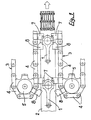
- Figure 2 is a front elevation view of the overall device of the invention; and
- Figure 3 is a perspective view of the ensemble of Figure 2.
- In the drawings it may be seen that the conveyor device of the invention, applicable to the conveyance of
lightweight parts 1 through parts washing machines, comprises aconveyor belt 2 on both sides of which at a slightly higher level there are disposed respectiveendless chains 3, of conventional type having mutually articulatedlinks 4. Saidchains 3 rotate around respective pairs ofsprockets 5, associated to a gear and transmission bar unit driven bydrive means 6, providing them with an intermittent movement. - On the
chains 3 there are disposed opposedly a plurality of pairs of front retainingstop members 7, fixedly attached tocertain links 4 of saidchains 3, with each of said pairs being adapted to retain apart 1 by the front upper leading portion thereof when saidpart 1 abuts said pair ofstop members 7, after thelinks 4 to which thestop members 7 are attached have just moved beyond the first pair ofsprockets 5. - In the same way, a like number of pairs of rear retaining
stop members 8 are provided, with each being adapted to retain in turn apart 1 by the rear portion and upper trailing edge thereof, when thelinks 4 to which the retainingstop members 8 are attached have just passed beyond the first pair ofsprockets 5. - Each
part 1 is thus retained by a pair of front retainingstop members 7 and by a further pair of rear retainingstop members 8 on theconveyor belt 2, throughout the whole of its passage through the washing machine. - At the end of such passage the
part 1 remains on theconveyor belt 2, but released from retention by the retainingstop members links 4 to which said stops 7 and 8 start to pass successively by the second pair ofsprockets 5. - Above the
conveyor belt 2 and below the path of the lower surface of theretaining stop members 7 and 8 (Figure 2) there are disposed two longitudinallateral guides 9, adapted to prevent undesired lateral movements of theparts 1, before these are retained by the frontretaining stop members 7. - Each of the
sprockets 5 of thechains 3 is associated with agearbox 10, the fourgearboxes 10 being coupled together bycorresponding shafts 11 andtransmission bars 12, to obtain synchronised intermittent movement thereof. - Having sufficiently described the nature of the invention, as well as the way of reducing it to practice, it is declared that everything which does not alter, change or modify the fundamental principle thereof, may be subject to variations of detail.
Claims (3)
- - A conveyor device for parts through machines for the washing thereof, particularly applicable to the conveyance of lightweight machined parts (1) through washing machines, in which said parts are successively subjected to operations of immersion in stirred washing liquid vats, washing liquid jets and/or solid material blasting and drying by hot air jets, characterised in that it comprises a conveyor belt (2) for said parts, provided with a continuous feed movement, on both sides of which there are disposed respective endless chains (3) of a conventional articulated link type at a slightly higher level, which rotate synchronously around respective pairs of sprockets (5) associated with a gear and transmission bar unit, driven by a motor means (6) providing them with an intermittent movement, there being opposedly disposed at least one first pair of front retaining stop members (7), fixedly attached to respective links (4) of said chains and adapted to hold a part by the front upper leading portion thereof, when said part abuts said pair of retaining stop members, just after the links to which the front retaining stop members are attached have passed beyond the first pair of sprockets, and at least one second pair of rear retaining stop members (8), adapted in turn to retain said part by the trailing end and upper trailing edge thereof, when the links to which the rear retaining stop members are attached have just passed beyond the first pair of sprockets, such that the part is held by both pairs of retaining stop members on the conveyor belt, throughout the whole of its passage through the interior of the washing machine, after which the part remains deposited on the conveyor belt, but released from the grip of the retaining stop members, from the time when the links to which said retaining stop members are attached start to move successively in front of said second pair of sprockets.
- - The device of claim 1, characterised in that above the conveyor belt and below the path of the lower surface of the front and rear retaining stop members there are disposed two longitudinal lateral guides (9), adapted to prevent undesired lateral movements of the parts, before these are retained by the retaining stop members.
- - The device of claim 1, characterised in that each of the sprockets of the chains is associated with a gearbox (10), the four gearboxes being coupled together by corresponding shafts (11) and transmission bars (12) for synchronised intermittent movement thereof.
Priority Applications (1)
| Application Number | Priority Date | Filing Date | Title |
|---|---|---|---|
| AT90500125T ATE97090T1 (en) | 1989-12-29 | 1990-12-19 | CONVEYING DEVICE FOR INDIVIDUAL PARTS IN WASHING PLANTS. |
Applications Claiming Priority (2)
| Application Number | Priority Date | Filing Date | Title |
|---|---|---|---|
| ES8904428A ES2023730A6 (en) | 1989-12-29 | 1989-12-29 | A conveyor device for parts through machines for the washing thereof. |
| ES8904428 | 1989-12-29 |
Publications (2)
| Publication Number | Publication Date |
|---|---|
| EP0435810A1 true EP0435810A1 (en) | 1991-07-03 |
| EP0435810B1 EP0435810B1 (en) | 1993-11-10 |
Family
ID=8265259
Family Applications (1)
| Application Number | Title | Priority Date | Filing Date |
|---|---|---|---|
| EP90500125A Expired - Lifetime EP0435810B1 (en) | 1989-12-29 | 1990-12-19 | A conveyor device for parts through machines for the washing thereof |
Country Status (5)
| Country | Link |
|---|---|
| EP (1) | EP0435810B1 (en) |
| JP (1) | JPH04106011A (en) |
| AT (1) | ATE97090T1 (en) |
| DE (1) | DE69004552T2 (en) |
| ES (2) | ES2023730A6 (en) |
Cited By (4)
| Publication number | Priority date | Publication date | Assignee | Title |
|---|---|---|---|---|
| CN105730984A (en) * | 2016-04-28 | 2016-07-06 | 陈浩涛 | High-accuracy automatic feeding mechanism applied in LED screen plug-in mounting machine |
| CN108042902A (en) * | 2018-01-25 | 2018-05-18 | 李洪玉 | A kind of automatic dipping liquid of medical cotton stick takes instrument |
| CN108263804A (en) * | 2018-01-25 | 2018-07-10 | 李正蒙 | A kind of automatic dipping liquid dispenser of Medical antiseptic cotton stick |
| CN116639434A (en) * | 2023-06-14 | 2023-08-25 | 兴化市银龙不锈钢有限公司 | Conveying equipment for production and manufacturing of non-magnetic drill collar |
Families Citing this family (1)
| Publication number | Priority date | Publication date | Assignee | Title |
|---|---|---|---|---|
| CN105668179B (en) * | 2016-03-02 | 2018-02-27 | 安徽省亮亮纺织有限公司 | One kind weaving roller Transporting equipment |
Citations (4)
| Publication number | Priority date | Publication date | Assignee | Title |
|---|---|---|---|---|
| US3454142A (en) * | 1967-02-27 | 1969-07-08 | John H Holstein | Positive straight line article conveying mechanism |
| US3550754A (en) * | 1967-09-27 | 1970-12-29 | Continental Can Co | Package forming machine |
| US3779367A (en) * | 1970-10-09 | 1973-12-18 | Auto Mat Corp | Cleaning machine |
| US4639968A (en) * | 1985-08-05 | 1987-02-03 | Seaton Ssk Engineering Inc. | Machine for cleaning castings |
-
1989
- 1989-12-29 ES ES8904428A patent/ES2023730A6/en not_active Expired - Lifetime
-
1990
- 1990-12-19 ES ES90500125T patent/ES2047896T3/en not_active Expired - Lifetime
- 1990-12-19 DE DE69004552T patent/DE69004552T2/en not_active Expired - Fee Related
- 1990-12-19 EP EP90500125A patent/EP0435810B1/en not_active Expired - Lifetime
- 1990-12-19 AT AT90500125T patent/ATE97090T1/en active
- 1990-12-27 JP JP2408188A patent/JPH04106011A/en active Pending
Patent Citations (4)
| Publication number | Priority date | Publication date | Assignee | Title |
|---|---|---|---|---|
| US3454142A (en) * | 1967-02-27 | 1969-07-08 | John H Holstein | Positive straight line article conveying mechanism |
| US3550754A (en) * | 1967-09-27 | 1970-12-29 | Continental Can Co | Package forming machine |
| US3779367A (en) * | 1970-10-09 | 1973-12-18 | Auto Mat Corp | Cleaning machine |
| US4639968A (en) * | 1985-08-05 | 1987-02-03 | Seaton Ssk Engineering Inc. | Machine for cleaning castings |
Cited By (6)
| Publication number | Priority date | Publication date | Assignee | Title |
|---|---|---|---|---|
| CN105730984A (en) * | 2016-04-28 | 2016-07-06 | 陈浩涛 | High-accuracy automatic feeding mechanism applied in LED screen plug-in mounting machine |
| CN108042902A (en) * | 2018-01-25 | 2018-05-18 | 李洪玉 | A kind of automatic dipping liquid of medical cotton stick takes instrument |
| CN108263804A (en) * | 2018-01-25 | 2018-07-10 | 李正蒙 | A kind of automatic dipping liquid dispenser of Medical antiseptic cotton stick |
| CN108042902B (en) * | 2018-01-25 | 2020-06-02 | 夏淑平 | Automatic liquid dipping and taking instrument for medical cotton swab |
| CN116639434A (en) * | 2023-06-14 | 2023-08-25 | 兴化市银龙不锈钢有限公司 | Conveying equipment for production and manufacturing of non-magnetic drill collar |
| CN116639434B (en) * | 2023-06-14 | 2024-03-19 | 兴化市银龙不锈钢有限公司 | Conveying equipment for production and manufacturing of non-magnetic drill collar |
Also Published As
| Publication number | Publication date |
|---|---|
| DE69004552T2 (en) | 1994-06-01 |
| ES2023730A6 (en) | 1992-02-01 |
| DE69004552D1 (en) | 1993-12-16 |
| JPH04106011A (en) | 1992-04-08 |
| ES2047896T3 (en) | 1994-03-01 |
| EP0435810B1 (en) | 1993-11-10 |
| ATE97090T1 (en) | 1993-11-15 |
Similar Documents
| Publication | Publication Date | Title |
|---|---|---|
| US4884676A (en) | Transferring and sorting apparatus | |
| DE3915217C2 (en) | Device for grouping objects | |
| US5657615A (en) | Spacing conveyor mechanism | |
| US4369875A (en) | Apparatus for isolation and supply of objects, in particular sweets, to a packing machine | |
| JP2651555B2 (en) | Article conveyer | |
| DE3842964A1 (en) | DEVICE FOR FORMING GROUPS OF ITEMS, IN PARTICULAR FOR AUTOMATIC PACKING ROADS | |
| EP0056946A1 (en) | An arrangement for the feeding of objects | |
| JP2553999B2 (en) | Method and device for side-by-side conveyance of articles | |
| WO2000017053A1 (en) | Food article loading head and method | |
| US3363743A (en) | Method and apparatus for transporting tubular articles | |
| EP0435810A1 (en) | A conveyor device for parts through machines for the washing thereof | |
| US5529167A (en) | Device for continuously feeding articles from a main conveying line to intermediate outlet ways arranged angularly with respect to the main line | |
| EP0329235A3 (en) | Dough piece bending device | |
| US4072227A (en) | Pin type transfer apparatus for apertured-workpieces | |
| JP2651564B2 (en) | Article conveyer | |
| EP0608103B1 (en) | Packaging machine with flight bar carton conveying system | |
| DE2944001C2 (en) | Transfer device | |
| EP0296386B1 (en) | Transporting device for rounded can bodies | |
| US4302867A (en) | Dual feed conveyor in gizzard processing machine | |
| US2460327A (en) | Solder wiper mechanism with shielding means | |
| EP0178028B1 (en) | In-line apparatus for containers, such as bottles and the like | |
| EP0924147B1 (en) | A conveyer | |
| CN217958592U (en) | Shaganjie incision device | |
| EP0441444B1 (en) | In-line device with overflow plate | |
| DE3211028C2 (en) | Conveyor system with a transfer device |
Legal Events
| Date | Code | Title | Description |
|---|---|---|---|
| PUAI | Public reference made under article 153(3) epc to a published international application that has entered the european phase |
Free format text: ORIGINAL CODE: 0009012 |
|
| AK | Designated contracting states |
Kind code of ref document: A1 Designated state(s): AT DE ES FR GB IT SE |
|
| 17P | Request for examination filed |
Effective date: 19911227 |
|
| 17Q | First examination report despatched |
Effective date: 19921009 |
|
| GRAA | (expected) grant |
Free format text: ORIGINAL CODE: 0009210 |
|
| AK | Designated contracting states |
Kind code of ref document: B1 Designated state(s): AT DE ES FR GB IT SE |
|
| PG25 | Lapsed in a contracting state [announced via postgrant information from national office to epo] |
Ref country code: SE Effective date: 19931110 Ref country code: AT Effective date: 19931110 |
|
| REF | Corresponds to: |
Ref document number: 97090 Country of ref document: AT Date of ref document: 19931115 Kind code of ref document: T |
|
| REF | Corresponds to: |
Ref document number: 69004552 Country of ref document: DE Date of ref document: 19931216 |
|
| ITF | It: translation for a ep patent filed |
Owner name: JACOBACCI CASETTA & PERANI S.P.A. |
|
| ET | Fr: translation filed | ||
| REG | Reference to a national code |
Ref country code: ES Ref legal event code: FG2A Ref document number: 2047896 Country of ref document: ES Kind code of ref document: T3 |
|
| PLBE | No opposition filed within time limit |
Free format text: ORIGINAL CODE: 0009261 |
|
| STAA | Information on the status of an ep patent application or granted ep patent |
Free format text: STATUS: NO OPPOSITION FILED WITHIN TIME LIMIT |
|
| PGFP | Annual fee paid to national office [announced via postgrant information from national office to epo] |
Ref country code: FR Payment date: 19941028 Year of fee payment: 5 |
|
| 26N | No opposition filed | ||
| PGFP | Annual fee paid to national office [announced via postgrant information from national office to epo] |
Ref country code: GB Payment date: 19941201 Year of fee payment: 5 |
|
| PGFP | Annual fee paid to national office [announced via postgrant information from national office to epo] |
Ref country code: DE Payment date: 19950218 Year of fee payment: 5 |
|
| PG25 | Lapsed in a contracting state [announced via postgrant information from national office to epo] |
Ref country code: GB Effective date: 19951219 |
|
| GBPC | Gb: european patent ceased through non-payment of renewal fee |
Effective date: 19951219 |
|
| PG25 | Lapsed in a contracting state [announced via postgrant information from national office to epo] |
Ref country code: FR Effective date: 19960830 |
|
| PG25 | Lapsed in a contracting state [announced via postgrant information from national office to epo] |
Ref country code: DE Effective date: 19960903 |
|
| REG | Reference to a national code |
Ref country code: FR Ref legal event code: ST |
|
| PGFP | Annual fee paid to national office [announced via postgrant information from national office to epo] |
Ref country code: ES Payment date: 20051110 Year of fee payment: 16 |
|
| PG25 | Lapsed in a contracting state [announced via postgrant information from national office to epo] |
Ref country code: IT Free format text: LAPSE BECAUSE OF NON-PAYMENT OF DUE FEES Effective date: 20051219 |
|
| REG | Reference to a national code |
Ref country code: ES Ref legal event code: FD2A Effective date: 20061220 |
|
| PG25 | Lapsed in a contracting state [announced via postgrant information from national office to epo] |
Ref country code: ES Free format text: LAPSE BECAUSE OF NON-PAYMENT OF DUE FEES Effective date: 20061220 |