EP0435486A2 - System and method for loosening and removing sludge and debris from the interior of a vessel of a heat exchanger - Google Patents
System and method for loosening and removing sludge and debris from the interior of a vessel of a heat exchanger Download PDFInfo
- Publication number
- EP0435486A2 EP0435486A2 EP90313255A EP90313255A EP0435486A2 EP 0435486 A2 EP0435486 A2 EP 0435486A2 EP 90313255 A EP90313255 A EP 90313255A EP 90313255 A EP90313255 A EP 90313255A EP 0435486 A2 EP0435486 A2 EP 0435486A2
- Authority
- EP
- European Patent Office
- Prior art keywords
- debris
- liquid
- loosening
- sludge
- heat exchanger
- Prior art date
- Legal status (The legal status is an assumption and is not a legal conclusion. Google has not performed a legal analysis and makes no representation as to the accuracy of the status listed.)
- Granted
Links
- 239000010802 sludge Substances 0.000 title claims abstract description 101
- 238000000034 method Methods 0.000 title claims abstract description 62
- 230000035939 shock Effects 0.000 claims abstract description 43
- 238000011010 flushing procedure Methods 0.000 claims abstract description 18
- 239000007788 liquid Substances 0.000 claims description 65
- 239000007921 spray Substances 0.000 claims description 10
- 238000011049 filling Methods 0.000 claims description 6
- 230000003134 recirculating effect Effects 0.000 claims description 3
- XLYOFNOQVPJJNP-UHFFFAOYSA-N water Substances O XLYOFNOQVPJJNP-UHFFFAOYSA-N 0.000 abstract description 130
- 238000004140 cleaning Methods 0.000 abstract description 21
- 238000005507 spraying Methods 0.000 abstract description 2
- 239000007789 gas Substances 0.000 description 8
- 239000008367 deionised water Substances 0.000 description 6
- 229910021641 deionized water Inorganic materials 0.000 description 6
- 238000000429 assembly Methods 0.000 description 5
- 230000000712 assembly Effects 0.000 description 5
- 238000009835 boiling Methods 0.000 description 4
- 230000008878 coupling Effects 0.000 description 4
- 238000010168 coupling process Methods 0.000 description 4
- 238000005859 coupling reaction Methods 0.000 description 4
- 238000001035 drying Methods 0.000 description 4
- 238000007599 discharging Methods 0.000 description 2
- 230000000694 effects Effects 0.000 description 2
- 238000001914 filtration Methods 0.000 description 2
- 239000002245 particle Substances 0.000 description 2
- 230000002285 radioactive effect Effects 0.000 description 2
- 229940125725 tranquilizer Drugs 0.000 description 2
- 239000003204 tranquilizing agent Substances 0.000 description 2
- 230000002936 tranquilizing effect Effects 0.000 description 2
- 238000006243 chemical reaction Methods 0.000 description 1
- 150000001875 compounds Chemical class 0.000 description 1
- 238000005202 decontamination Methods 0.000 description 1
- 230000003588 decontaminative effect Effects 0.000 description 1
- 238000000151 deposition Methods 0.000 description 1
- 239000002360 explosive Substances 0.000 description 1
- 239000010419 fine particle Substances 0.000 description 1
- 238000010304 firing Methods 0.000 description 1
- 239000012535 impurity Substances 0.000 description 1
- 239000011261 inert gas Substances 0.000 description 1
- 238000009434 installation Methods 0.000 description 1
- 238000005342 ion exchange Methods 0.000 description 1
- SZVJSHCCFOBDDC-UHFFFAOYSA-N iron(II,III) oxide Inorganic materials O=[Fe]O[Fe]O[Fe]=O SZVJSHCCFOBDDC-UHFFFAOYSA-N 0.000 description 1
- 238000002955 isolation Methods 0.000 description 1
- 238000012423 maintenance Methods 0.000 description 1
- 239000000463 material Substances 0.000 description 1
- 230000007246 mechanism Effects 0.000 description 1
- 239000013618 particulate matter Substances 0.000 description 1
- 230000001737 promoting effect Effects 0.000 description 1
- 230000010349 pulsation Effects 0.000 description 1
- 239000008213 purified water Substances 0.000 description 1
- 239000007787 solid Substances 0.000 description 1
- 238000010408 sweeping Methods 0.000 description 1
Images


Classifications
-
- F—MECHANICAL ENGINEERING; LIGHTING; HEATING; WEAPONS; BLASTING
- F22—STEAM GENERATION
- F22B—METHODS OF STEAM GENERATION; STEAM BOILERS
- F22B37/00—Component parts or details of steam boilers
- F22B37/02—Component parts or details of steam boilers applicable to more than one kind or type of steam boiler
- F22B37/48—Devices for removing water, salt, or sludge from boilers; Arrangements of cleaning apparatus in boilers; Combinations thereof with boilers
-
- F—MECHANICAL ENGINEERING; LIGHTING; HEATING; WEAPONS; BLASTING
- F28—HEAT EXCHANGE IN GENERAL
- F28G—CLEANING OF INTERNAL OR EXTERNAL SURFACES OF HEAT-EXCHANGE OR HEAT-TRANSFER CONDUITS, e.g. WATER TUBES OR BOILERS
- F28G7/00—Cleaning by vibration or pressure waves
-
- F—MECHANICAL ENGINEERING; LIGHTING; HEATING; WEAPONS; BLASTING
- F22—STEAM GENERATION
- F22B—METHODS OF STEAM GENERATION; STEAM BOILERS
- F22B37/00—Component parts or details of steam boilers
- F22B37/02—Component parts or details of steam boilers applicable to more than one kind or type of steam boiler
- F22B37/48—Devices for removing water, salt, or sludge from boilers; Arrangements of cleaning apparatus in boilers; Combinations thereof with boilers
- F22B37/483—Devices for removing water, salt, or sludge from boilers; Arrangements of cleaning apparatus in boilers; Combinations thereof with boilers specially adapted for nuclear steam generators
Definitions
- This invention generally relates to the cleaning of heat exchanger vessels, and is specifically concerned with a system and a method for loosening and removing sludge and debris from the interior of a vessel of a heat exchanger.
- shock waves Methods for cleaning the interior of the secondary side of a nuclear steam generator by means of shock waves introduced into water are known in the prior art.
- the nuclear steam generator is shut down and drained.
- enough demineralized water is introduced into the secondary side to completely submerge the tubesheet and the bottom ends of the bundle of heat exchanger tubes mounted therein.
- Shock waves are then introduced into this water to loosen sludge and debris that accumulates around the top side of the tubesheet and the bottom ends of the heat exchanger tubes.
- shock waves may be generated by directly introducing a pressurized pulse of an inert gas within the water to produce an explosive, omnidirectional shock wave that impinges against all the heat exchanger components that are submerged within the water present in the secondary side of the generator.
- shock waves may take the form of forceful fountains of water which erupt from the surface of the water collected within the secondary side and forcefully slap against the sludge-collecting spaces between the heat exchanger tubes and support plates to clean them.
- a water cannon powered by pressurized pulses of gas is used to generate high velocity bursts of water below the water level which forcefully impinge against collected sludge and debris, thereby loosening and removing it.
- a gas operated pressure pulse generator is used to generate the shock waves which loosen the sludge and debris, either directly as illustrated for example in the pressure pulse cleaning technique disclosed in U.S. Patent 4,655,846.
- the same water that is used to propagate the sludge-loosening shock waves is continuously recirculated through the hand-holes located at the bottom of the steam generator and filtered in much the same manner as an ordinary pool vacuum in order to entrain and remove the sludge and other debris loosened by the shock waves.
- shock wave cleaning techniques have shown themselves to be a very promising way in which to remove the stubborn deposits of sludge which tend to accumulate not only on the upper surface of the tubesheet, but in the small annular spaces between the support plates and the heat exchanger tubes which are present inside the secondary side of such generators.
- the applicants have found that all of these shock wave cleaning techniques have fallen short of fulfilling their full potential due to the lack of effectiveness of the water circulation employed to entrain and remove and loosened particles of sludge and debris out of the secondary side of the steam generator.
- water is circumferentially circulated around the bottom of the secondary side just above the tubesheet by pumps which simultaneously inject and withdraw the water out through the sludge lancing ports of the steam generator.
- the invention is both a system and a method for loosening and removing sludge and debris from the interior of the vessel of a heat exchanger, which may be a nuclear steam generator, that contains one or more heat exchanger components, such as tubes, a tubesheet, and support plates.
- a heat exchanger which may be a nuclear steam generator, that contains one or more heat exchanger components, such as tubes, a tubesheet, and support plates.
- the invention in its broad form is a method for loosening and removing sludge and debris from the interior of the vessel of a heat exchanger having a top portion, a bottom portion and a secondary side and that contains one or more heat exchanger components, said method including introducing a sufficient amount of liquid in said heat exchanger vessel to submerge at least a portion of the interior thereof that includes some of said sludge, debris and heat exchanger components, and generating a succession of shock waves within the liquid to loosen said sludge and debris, characterized by the step of vertically flushing the interior of the vessel by suctioning off said liquid from the bottom portion of said vessel while simultaneously introducing liquid into the top portion of said vessel.
- the liquid used to vertically flush the interior of the vessel may also be used to fill the vessel to a level which completely submerges all of the heat exchanger components therein by merely suctioning the liquid out of the vessel at a rate slower than liquid is introduced at the top of the vessel. Conversely, draining all of the liquid out of the vessel is accomplished by merely suctioning liquid out of the vessel at a rate faster than liquid is introduced into the top portion of the vessel. The flow rate of the liquid suctioned out of the bottom portion of the vessel is fast enough to entrain and remove sludge and debris from the interior of the vessel.
- the same liquid suctioned from the bottom portion of the vessel is recirculated and reintroduced into the top portion of the vessel after the sludge and debris entrained therein have been removed by suitable filtration assemblies in order to converse the amount of liquid needed to implement the vertical flush.
- the liquid introduced into the top portion of the vessel is preferably forcefully sprayed over the heat exchanger components contained therein in order to enhance the effectiveness of the vertical flush in removing sludge and debris.
- shock waves may be in the form of omnidirectional shock waves of water created by the pulses or pressurized gas discharged into the water.
- shockwaves may be either in the form of fountains of water that erupt above the surface of the water and forcefully slap against the heat exchanger components, or even projectiles of water that are discharged below the water level by a water cannon.
- the interior of the secondary side is vertically flushed by suctioning water through the sludge lance ports in the pressure vessel located at the bottom portion of the generator while forcefully spraying water down over the tube bundle through special hoses inserted through the manways located in the swirl vane area of the generator.
- the secondary side is slowly filled with water to a level that completely immerses the bundle of heat exchanger tubes contained therein by introducing water at a rate of 400 liters per minute while suctioning water at a rate of only 320 liters per minute.
- This filling step of the method preferably lasts between about 12 to 20 hours, depending upon the condition of the secondary side.
- both the filling rate and the suctioning rate are set at equilibrium for a period of between 6 and 24 hours, and preferably between 6 and 8 hours while the succession of shock waves continues.
- the secondary side is drained of water by suctioning the water out of the bottom portion of the steam generator at a rate of about 400 liters per minute while filling it at the top portion at a rate of only about 320 liters per minute.
- This draining step takes between about 12 and 20 hours, again depending upon the condition of the nuclear steam generator.
- the invention in its broad form is also a system for loosening and removing sludge and debris from the interior of the vessel of a heat exchanger having top and bottom portions and containing one or more heat exchanger components immersed in a liquid, said system having means for generating a succession of pressure pulses to create shock waves in said liquid to loosen said sludge and debris, characterized by means for vertically flushing said heat exchanger components while said pressure pulse means creates sludge loosening shock waves.
- the flushing means is the combination of a suction and discharge pump, one or more suction nozzles connected to the inlet end of the pump for sucking out water and sludge entrained therein, one or more discharge nozzles connected to the discharge end of the pump for directing a forceful spray of water over the components within the heat exchanger vessel to entrain loosened sludge into the water, and a filtration assembly for removing not only the sludge and debris entrained within the water that is sucked out of the bottom of the heat exchanger vessel, but also any dissolved ionic species that may be present in the liquid.
- Both the method and the system of the invention greatly enhance both the effectiveness and the speed of cleaning techniques which utilize shock waves to loosen and remove sludge and debris from the interior of heat exchanger vessels,such as pressure pulse, water slap and water cannon cleaning techniques.
- Nuclear steam generator 1 generally includes a primary side 3 and a secondary side 5 which are hydraulically isolated from one another by a tubesheet 7.
- the primary side 3 is bowl-shaped, and is divided into two, hydraulically isolated halves by means of a divider plate 8.
- One of the halves of the primary side 3 includes a water inlet 9 for receiving hot, radioactive water that has been circulated through the core barrel of a nuclear reactor (not shown), while the other half includes a water outlet 13 for discharging this water back to the core barrel.
- This hot, radioactive water circulates through the U-shaped heat exchanger tubes 22 contained within the secondary side 5 of the steam generator 1 from the inlet half of the primary side 3 to the outlet half (see flow arrows).
- the water-receiving half of the primary side 3 is called the inlet channel head 15, while the water-discharging half is called the outlet channel head 17.
- the secondary side 5 of the steam generator 1 includes an elongated tube bundle 20 formed from approximately 3500 U-shaped heat exchanger tubes 22.
- Each of the heat exchanger tubes 22 includes a hot leg 24, a U-bend 26 at its top, and a cold leg 28.
- the bottom end of the hot and cold legs 24, 28 of each heat exchanger tube 22 is securely mounted within bores in the tubesheet 7, and each of these legs terminates in an open end.
- the open ends of all the hot legs 24 communicate with the inlet channel head 15, while the open ends of all of the cold legs 28 communicate with the outlet channel head 17.
- heat from the water in the primary side 3 circulating within the U-shaped heat exchanger tues 22 is transferred to nonradioactive feed water in the secondary side 5 of the generator 1 in order to generate nonradioactive steam.
- support plates 30 are provided to securely mount and uniformly space the heat exchanger tubes 22 within the secondary side 5.
- Each of the support plates 30 includes a plurality of bores 32 which are only slightly larger than the outer diameter of the heat exchanger tubes 22 extending therethrough.
- a plurality of circulation ports 34 is also provided in each of the support plates 30. Small annular spaces or crevices 37 exist between the outer surface of the heat exchanger tubes 22, and the inner surface of the bores 32.
- annular crevices 37 exist between the lower ends of both the hot and cold legs 24 and 28 of each of the heat exchanger tubes 22, and the bores of the tubesheet 7 in which they are mounted.
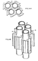
- the openings in the support plates 30 are not circular, but instead are trifoil or quatrefoil-shaped as is illustrated in Figures 4A and 4B.
- the heat exchanger tubes 22 are supported along either three or four equidistally spaced points around their circumferences. Because such broached openings 38 leave relatively large gaps at some points between the heat exchanger tubes 22 and the support plate 30, there is no need for separate circulation ports 34.
- the top portion of the secondary side 5 of the steam generator 1 includes a steam drying assembly 44 for extracting the water out of the wet steam produced when the heat exchanger tubes 22 boil the nonradioactive water within the secondary side 5.
- the steam drying assembly 44 includes a primary separator bank 46 formed from a battery of swirl vane separators, as well as a secondary separator bank 48 that includes a configuration of vanes that define a tortuous path for moisture-laden steam to pass through.
- a steam outlet 49 is provided over the steam drying assembly 44 for conducting dried steam to the blades of a turbine coupled to an electrical generator.
- the upper portion of the secondary side 5 includes a pair of opposing manways 50a, 50b that afford access to the separator bank 48.
- the middle portion of the secondary side 5 contains a tube wrapper 52 that is disposed between the tube bundle 22 and the outer shell of the steam generator 1 in order to provide a downcomer path for water extracted from the wet steam that rises through the steam drying assembly 44.
- a pair of opposing sludge lance ports 53a, 53b are provided in some models of steam generators to provide access for high pressure hoses that wash away much of the sludge which accumulates over the top of the tubesheets 7 during the operation of the generator 1.
- These opposing sludge lance ports 53a, 53b are typically centrally aligned between the hot and cold legs 24 and 28 of each of the heat exchanger tubes 22. It should be noted that in some steam generators, the sludge lance ports are not oppositely disposed 180 degrees from one another, but are only 90 degrees apart. Moreover, in other steam generators, only one such sludge lance port is provided.
- tube lanes 54 the elongated areas between rows of tubes 22 on the tubesheet 7 are known as tube lanes 54, while the relatively wider, elongated area between the hot and cold legs of the most centrally-disposed heat exchanger tubes 22 is known as the central tube lane 55.
- These tube lanes 54 are typically an inch or two wide in steam generators whose tubes 22 are arranged in a square pitch, such as that shown in Figures 3A, 3B and 3C.
- Narrower tube lanes 54 are present in steam generators whose heat exchanger tubes 22 are arranged in a denser, triangular pitch such as shown in Figures 4A and 4B.
- a central tube lane 55 that is wider than the other tube lanes 54 is disposed between the sludge lance ports 53a, 53b.
- a pressure pulse cleaning system may be provided which comprises a pair of pressure pulse generator assemblies 60a, 60b having nozzles 62 mounted in the two sludge lance ports 53a, 53b, as is shown in Figure 5.
- Each of the pressure generator assemblies includes a mounting flange 63 that allows it to be firmly secured over its respective port 53a, 53b.
- the secondary side 5 is filled with enough demineralized water to at least cover the tubesheet 7, the lower ends of the heat exchanger tubes 22, and the nozzles 62 of the pressure pulse generator assemblies 60a, 60b.
- the pressure pulse generators 60a, 60b generate a succession of pulses of pressurized gas that in turn create omnidirectional shock waves in the water contained within the secondary side 5. These shock waves loosen sludge and debris from the upper surface of the tubesheet 7, and even more importantly from the crevices 37 or gaps 38 between the exchanger tubes 22 and the bores 32 of the support plates 30.
- the instant invention is both a system 70 (see Fig. 6) and method for flushing the loosened sludge and debris completely out of the interior of the secondary side 5.
- the system of the invention comprises a vertical flush and recirculation system 70 for both draining and filling the secondary side 5 with clean, deionized water while vertically flushing the tube bundle 28 and the tubesheet 7 with a forceful spray of water.
- the system 70 includes a pair of suction hoses 72a, 72b that extend through the circular mounting flange 63 of each of the pressure pulse generator assemblies 60a, 60b by way of a fitting. The distal end of each of these hoses is connected to three suction nozzles 74a, 74b and 74c which lie on top of the tubesheet 7.
- Nozzles 74a and 74c are aligned along the periphery of the tubesheet 7 while nozzle 74b is aligned along the central tube lane 55 in order to rapidly draw off water from a broad section of the top surface of the tubesheet 7.
- Each of the nozzles 74a, 74b and 74c is approximately 4-5.25 cm (1.5-2.0 inches) in diameter.
- each of the suction hoses 72a, 72b are connected to a manifold 75 which is in turn connected to the inlet of a diaphragm pump 76 by way of conduit 78.
- a diaphragm-type pump 76 is preferred at this point in the flushing and recirculation system 70 since the water withdrawn through the suction hoses 72a, 72b may have large particles of suspended sludge which, while easily handled by a diaphragm-type pump, could damage or even destroy a rotary or positive displacement-type pump.
- the output of the diaphragm pump 76 is in turn serially connected first to a tranquilizer 80 and then a flow meter 82.
- the tranquilizer 80 "evens out” the pulsations of water created by the diaphragm pump 76 and thus allows the flow meter 82 to display the average rate of the water flow out of the diaphragm pump 76.
- the output of the flow meter 82 is connected to the inlet of a surge tank 84 via conduit 86.
- the surge tank 84 has an approximately 1200 liter (300 gallon) capacity.
- the outlet of the surge tank 84 is connected to the inlet of a flow pump 88 by way of a single conduit 90, while the output of the pump 88 is connected to the inlet of a cyclone separator 92 via conduit 94.
- the surge tank 84 accumulates the flow of water generated by the diaphragm pump 76 and smoothly delivers this water to the inlet of the pump 88.
- the pump 88 in turn generates a sufficient pressure head in the recirculating water so that a substantial portion of the sludge suspended in the water will be centrifugally flung out of the water as it flows through the cyclone separator 92.
- a 0.0001 to 0.0003 cm (one to three micron) bag filter 96 that is serially connected to a 0.0001 cm (one micron) cartridge filter 98.
- These filters 96 and 98 remove any small particulate matter which still might be suspended in the water after it passes through the cyclone separator 92.
- Downstream of the filters 96 and 98 is a 2000 liter (500 gallon) supply tank 100 that is connected to the outlet of filter 98 by conduit 102.
- Supply tank 100 is connected to an outlet conduit 102 that leads to the inlet of another flow pump 104.
- the outlet of the flow pump 104 is in turn connected to the inlet of a de-mineralizer bed 106 by way of conduit 108.
- the purpose of the flow pump 104 is to establish enough pressure in the recirculating water so that it flows through the serially connected ion exchange columns (not shown) in the demineralizer bed 106 at an acceptably rapid flow rate.
- the power capacity of flow pump 104 is preferably somewhere between 203 and 406 hp (metric).
- the purpose of the demineralizer bed 106 is to remove all ionic species from the water so that they will have no opportunity to re-enter the secondary side 5 of the generator 1 and create new sludge deposits.
- a first T-joint 110 Located downstream of the demineralizer bed 106 is a first T-joint 110 whose inlet is connected to conduit 112 as shown.
- An isolation valve 114 and a drain valve 116 are located downstream of the two outlets of the T-joint 110 as shown to allow the water used in the cleaning method to be drained into the decontamination facility of the utility.
- Located downstream of the T-joint 110 is another T-joint 118 whose inlet is also connected to conduit 112 as shown.
- Diverter valves 120a and 120b are located downstream of the outlet of T-joint 110 as indicated. Normally valve 120a is open and valve 120b is closed.
- valves 120a and 120b can be partially closed and partially opened, respectively.
- Flow meters 122a, 122b are located downstream of the valves 120a and 120b so that an appropriate bifurcation of the flow from conduit 112 can be had to effect such a simultaneous drain-fill step.
- the conduit that valve 120b and flowmeter 122b are mounted in terminates in a quick-connect coupling 124.
- valves 120a and 120b are mounted on a wheeled cart (not shown) and conduit 112 is formed from a flexible hose to form a portable coupling station.
- inlet conduit 112 Downstream of the portable coupling station, inlet conduit 112 terminates in the inlet of a T-joint 126 that bifurcates the inlet flow of water between inlet conduits 128a and 128b.
- Inlet conduits 128a and 128b each include flowmeters 130a, 130b to help the system operator adjust flow valves 132a, 132b so that the flow of water from conduit 112 is evenly divided through inlet conduits 128a and 128b.
- each of the inlet conduits 128a and 128b is connected to a manifold (not shown) that is mounted on the covers 50.5a and 50.5b of the manways 50a and 50b.
- Each of these manifolds is in turn fluidly connected to a pair of flexible spray nozzles 134a,b and 136a,b, respectively.
- the flexible nozzles 134a,b and 136a,b extend through the primary separator bank 46 so that their open distal ends are suspended over the tube bundle 20 a distance of about 15.72-26.20 cm (6-10 inches).
- the four nozzles 134a,b and 136a,b are roughly arranged in a square configuration over the tube bundle 20 so that the streams of water discharged therefrom uniformly strike the top portion of the tube bundle 20.
- the nozzles 134a,b and 136a,b are 4.0-5.25 cm (1.5-2.0 inches) in diameter.
- nozzles 134a,b and 136a,b are each formed from a conduit material that is flexible enough so that the reaction forces generated by the pressurized streams of water discharged from its open distal end causes it to whip around in a more or less random pattern, which in turn renders the distribution of sprayed water even more uniform over the top of the tube bundle 20.
- Water is initially supplied to the flushing and recirculation system 70 through deionized water supply 140, which may be the deionized water reservoir of the utility being serviced.
- Water supply 140 includes an outlet conduit 142 connected to the inlet of another flow pump 144.
- the outlet of the flow pump 144 is connected to another conduit 146 whose outlet is in turn connected to the supply tank 100.
- a check valve 148 is provided in conduit 146 to insure that water from the supply tank 100 cannot back up into the deionized water supply 140.
- the flushing and recirculation system 70 illustrated in Figure 6 is installed onto the secondary side 5 of a nuclear steam generator 1. This is accomplished by bolting the mounting flanges 63 of the pressure pulse generators 60a, 60b over the sludge lancing ports 53a and 53b located in the bottom portion of the secondary side 5. This has the effect of positioning the suction nozzles 74a, 74b and 74c that are mounted onto each of the pressure pulse generator 60a, 60b into the position illustrated in Figure 3A, wherein nozzles 74a and 74c are oriented along the periphery of the tubesheet 7 inside of the tube wrapper 52, and nozzle 74b is oriented along the main tube lane 55.
- flow pump 144 is actuated to fill supply tank 100 with purified and deionized water from water supply 140.
- flow pump 104 is actuated with valves 114 and 120a open and valve 120b closed in order to introduce this deionized water into the inlet conduits 128a and 128b.
- flow valves 132a and 132b are adjusted so that the flow through each of these conduits 128a and 128b is substantially equal.
- diaphragm pump 76 is started so that the suction nozzles 74a, 74b and 74c connected to the suction hoses 72a and 72b start to suck out the water that has collected within the secondary side 5.
- the diaphragm pump 76 pulls out approximately 160 liters of water per minute from each of the suction hoses 72a and 72b.
- the flow pump 104 is adjusted so that each of the inlet conduits 128a and 128b introduces approximately 200 liters of water per minute through the flexible spray nozzles 134a,b and 136a,b.
- the flushing and recirculation system 70 continues to operate in this mode until the tube bundle 20 is completely submerged in water. Depending upon the amount of sludge that has accumulated in the secondary side 5 of the steam generator 1 being cleaned, this step of the method of the invention may take anywhere between 12 and 20 hours.
- the sludge-containing water discharged through the suction hoses 72a and 72b is purified by the cyclone separator 92, the filter bag 96, the cartridge filter 98, and the demineralizer bed 106 before being reintroduced into the steam generator 1 through the inlet conduits 128a and 128b.
- the system 70 will contain approximately 80,000 liters of water, 72,000 of which is disposed within the secondary side 5 of the steam generator 1, and 8,000 liters of which is in the pipelines and tanks of the balance of the flushing and recirculation system 70.
- the operation of the diaphragm pump 76 is speeded up in order to increase the suction flow through the suction hoses 72a and 72b from 320 liters to 400 liters per minute thereby equalizing it at the rate at which water is suctioned off from the secondary side 5 to the rate at which water is introduced into the secondary side 5 through the inlet conduits 28a and 28b.
- the level of the water within the secondary side 5 is maintained at equilibrium above the tube bundle 20 for preferably between 6 and 8 hours, during which time the pressure pulse generator 60a and 60b continue to be operated.
- the water inside the secondary side 5 of the steam generator 1 is slowly drained by reducing the flow of water through the inlet conduits 128a and 128b from 400 liters per minute to 320 liters per minute. This results a net loss of 80 liters per minute of water from the secondary side 5.
- diverter valve 120b is partially opened while diverter valve 120a is partially closed in order to divert some of the 80,000 liters of water which has accumulated into the system 70 back to the utility through quick disconnect coupling 124.
- this draining step lasts between abut 12 and 20 hours, depending upon the condition of the secondary side 5 of the steam generator 1. It is during this step that the forceful spray of water emitted by the four spray nozzles 134a,b and 136a,b is the most effective in removing sludge from the tube bundle 20, as a great deal of the sludge has been loosened by the succession of shock waves generated by the succession of pressurized pulses of gas emitted by the pressure pulse generator 60a and 60b.
- the steady downstream of water from these nozzles 134a,b and 136a,b runs through the annular spaces and gaps 37 and 38 existing between the heat exchanger tubes 22 and the bores 32 which surround them and the support plate 30, thereby effectively pushing this sludge and debris downwardly to the top surface of the tubesheet 7 where it is entrained and swept away by the water flowing through the suction nozzles 74a, 74b and 74c.
- the pressure pulse generators 60a and 60b continue to be operated at all times through this draining step.
Landscapes
- Engineering & Computer Science (AREA)
- Physics & Mathematics (AREA)
- Mechanical Engineering (AREA)
- General Engineering & Computer Science (AREA)
- Thermal Sciences (AREA)
- High Energy & Nuclear Physics (AREA)
- Chemical & Material Sciences (AREA)
- Combustion & Propulsion (AREA)
- Cleaning In General (AREA)
Abstract
Description
- This invention generally relates to the cleaning of heat exchanger vessels, and is specifically concerned with a system and a method for loosening and removing sludge and debris from the interior of a vessel of a heat exchanger.
- Methods for cleaning the interior of the secondary side of a nuclear steam generator by means of shock waves introduced into water are known in the prior art. In all of these methods, the nuclear steam generator is shut down and drained. Next, enough demineralized water is introduced into the secondary side to completely submerge the tubesheet and the bottom ends of the bundle of heat exchanger tubes mounted therein. Shock waves are then introduced into this water to loosen sludge and debris that accumulates around the top side of the tubesheet and the bottom ends of the heat exchanger tubes. Such shock waves may be generated by directly introducing a pressurized pulse of an inert gas within the water to produce an explosive, omnidirectional shock wave that impinges against all the heat exchanger components that are submerged within the water present in the secondary side of the generator. Alternatively, these shock waves may take the form of forceful fountains of water which erupt from the surface of the water collected within the secondary side and forcefully slap against the sludge-collecting spaces between the heat exchanger tubes and support plates to clean them. In still another type of shock wave cleaning process, a water cannon powered by pressurized pulses of gas is used to generate high velocity bursts of water below the water level which forcefully impinge against collected sludge and debris, thereby loosening and removing it. In all three methods, a gas operated pressure pulse generator is used to generate the shock waves which loosen the sludge and debris, either directly as illustrated for example in the pressure pulse cleaning technique disclosed in U.S. Patent 4,655,846. In this technique, the same water that is used to propagate the sludge-loosening shock waves is continuously recirculated through the hand-holes located at the bottom of the steam generator and filtered in much the same manner as an ordinary pool vacuum in order to entrain and remove the sludge and other debris loosened by the shock waves.
- Since their inception, such shock wave cleaning techniques have shown themselves to be a very promising way in which to remove the stubborn deposits of sludge which tend to accumulate not only on the upper surface of the tubesheet, but in the small annular spaces between the support plates and the heat exchanger tubes which are present inside the secondary side of such generators. However, the applicants have found that all of these shock wave cleaning techniques have fallen short of fulfilling their full potential due to the lack of effectiveness of the water circulation employed to entrain and remove and loosened particles of sludge and debris out of the secondary side of the steam generator. In all of these techniques, water is circumferentially circulated around the bottom of the secondary side just above the tubesheet by pumps which simultaneously inject and withdraw the water out through the sludge lancing ports of the steam generator. While such a flow of water effectively removes sludge and debris directly in front of the discharge and withdrawal ports of the recirculation system and around the edges of the tubesheet where the concentration of heat exchanger tubes is at its lowest density, the applicants have found that the currents generated by such recirculation systems are ineffective in sweeping the sludge and debris which accumulates on and around the central portion of the tubesheet where the density of the bundle of heat exchanger tubes is greatest. If this dislodged sludge is not removed from the center portion of the tubesheet, the fine particles which constitute such sludge are capable of settling onto the tubesheet and densely depositing themselves into the crevice regions between the tubesheet and the legs of the heat exchanger tubes mounted therein, thereby defeating one of the primary purposes of the cleaning operation. Of course, such sludge can be removed by conventional sludge-lancing techniques. However, the addition of another major step in the cleaning operation protracts the time necessary to complete the cleaning operation by as much as a half a day. This is a significant drawback, as a utility typically looses over $500,000 U.S. in revenues per each day of down-time.
- Clearly, there is a need for an improved recirculation system for use in conjunction with a shock wave cleaning operation of a nuclear steam generator which effectively entrains and removes all the sludge and debris loosened by the shock waves without adding any significant amount of time to the cleaning operation. Ideally, such a recirculation system should improve the efficiency of the cleaning operation without adding any significant expenses in set up time or equipment costs. Finally, the new recirculation system should be compatible with all types of shock wave cleaning techniques, including pressure pulse, water cannon and water slap cleaning techniques.
- Generally speaking, the invention is both a system and a method for loosening and removing sludge and debris from the interior of the vessel of a heat exchanger, which may be a nuclear steam generator, that contains one or more heat exchanger components, such as tubes, a tubesheet, and support plates.
- In part, the invention in its broad form is a method for loosening and removing sludge and debris from the interior of the vessel of a heat exchanger having a top portion, a bottom portion and a secondary side and that contains one or more heat exchanger components, said method including introducing a sufficient amount of liquid in said heat exchanger vessel to submerge at least a portion of the interior thereof that includes some of said sludge, debris and heat exchanger components, and generating a succession of shock waves within the liquid to loosen said sludge and debris, characterized by the step of vertically flushing the interior of the vessel by suctioning off said liquid from the bottom portion of said vessel while simultaneously introducing liquid into the top portion of said vessel.
- The liquid used to vertically flush the interior of the vessel may also be used to fill the vessel to a level which completely submerges all of the heat exchanger components therein by merely suctioning the liquid out of the vessel at a rate slower than liquid is introduced at the top of the vessel. Conversely, draining all of the liquid out of the vessel is accomplished by merely suctioning liquid out of the vessel at a rate faster than liquid is introduced into the top portion of the vessel. The flow rate of the liquid suctioned out of the bottom portion of the vessel is fast enough to entrain and remove sludge and debris from the interior of the vessel. Preferably, the same liquid suctioned from the bottom portion of the vessel is recirculated and reintroduced into the top portion of the vessel after the sludge and debris entrained therein have been removed by suitable filtration assemblies in order to converse the amount of liquid needed to implement the vertical flush. Additionally, the liquid introduced into the top portion of the vessel is preferably forcefully sprayed over the heat exchanger components contained therein in order to enhance the effectiveness of the vertical flush in removing sludge and debris.
- When the method of the invention is applied to the secondary side of a nuclear steam generator, a sufficient amount of water is first introduced into the secondary side to immerse at least the tubesheet and the lower ends of the heat exchanger tubes. Next, a succession of pressure pulses is generated within the water collected within the secondary side by means of pulses and pressurized gas to create shock waves that loosen the sludge and debris. These shock waves may be in the form of omnidirectional shock waves of water created by the pulses or pressurized gas discharged into the water. Alternatively, these shockwaves may be either in the form of fountains of water that erupt above the surface of the water and forcefully slap against the heat exchanger components, or even projectiles of water that are discharged below the water level by a water cannon.
- As soon as a sufficient amount of water is collected within the secondary side to allow debris and sludge loosening shock waves to be effectively generated within the secondary side, the interior of the secondary side is vertically flushed by suctioning water through the sludge lance ports in the pressure vessel located at the bottom portion of the generator while forcefully spraying water down over the tube bundle through special hoses inserted through the manways located in the swirl vane area of the generator. While the succession of shock waves continues to be generated, the secondary side is slowly filled with water to a level that completely immerses the bundle of heat exchanger tubes contained therein by introducing water at a rate of 400 liters per minute while suctioning water at a rate of only 320 liters per minute. This filling step of the method preferably lasts between about 12 to 20 hours, depending upon the condition of the secondary side. After the bundle of heat exchanger tubes has been completely submerged, both the filling rate and the suctioning rate are set at equilibrium for a period of between 6 and 24 hours, and preferably between 6 and 8 hours while the succession of shock waves continues. Finally, the secondary side is drained of water by suctioning the water out of the bottom portion of the steam generator at a rate of about 400 liters per minute while filling it at the top portion at a rate of only about 320 liters per minute. This draining step takes between about 12 and 20 hours, again depending upon the condition of the nuclear steam generator.
- The invention in its broad form is also a system for loosening and removing sludge and debris from the interior of the vessel of a heat exchanger having top and bottom portions and containing one or more heat exchanger components immersed in a liquid, said system having means for generating a succession of pressure pulses to create shock waves in said liquid to loosen said sludge and debris, characterized by means for vertically flushing said heat exchanger components while said pressure pulse means creates sludge loosening shock waves.
- In the preferred embodiment, the flushing means is the combination of a suction and discharge pump, one or more suction nozzles connected to the inlet end of the pump for sucking out water and sludge entrained therein, one or more discharge nozzles connected to the discharge end of the pump for directing a forceful spray of water over the components within the heat exchanger vessel to entrain loosened sludge into the water, and a filtration assembly for removing not only the sludge and debris entrained within the water that is sucked out of the bottom of the heat exchanger vessel, but also any dissolved ionic species that may be present in the liquid.
- Both the method and the system of the invention greatly enhance both the effectiveness and the speed of cleaning techniques which utilize shock waves to loosen and remove sludge and debris from the interior of heat exchanger vessels,such as pressure pulse, water slap and water cannon cleaning techniques.
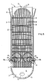
- Figure 1 is a perspective view of a nuclear steam generator with part of its exterior walls removed to display the interior of the generator, and the manner in which the discharge nozzles of the system of the invention are mounted through the manways located at the top of the secondary side;
- Figure 2 is a side, cross-sectional view of the steam generator illustrated in Figure 1 along the line 2-2;
- Figure 3A is a plan cross-sectional view of the steam generator illustrated in Figure 1 along the
line 3A-3A, illustrating the manner in which the suction nozzles of the system are mounted through the sludge lance ports located at the bottom of the secondary side; - Figure 3B is an enlargement of the portion of the support plate illustrated in Figure 3A that is enclosed in dotted lines;
- Figure 3C is a side cross-sectional view of the section of support plate illustrated in Figure 3B along the
line 3C-3C; - Figure 4A is a plan view of a section of a broached trifoil support plate, illustrating the relatively large gaps between the heat exchanger tubes of the generator and the trifoil openings;
- Figure 4B is a perspective view of the broached trifoil support plate illustrated in Figure 4A;
- Figure 5 is another side cross-sectional view of the steam generator illustrated in Figure 1 along the line 5-5, and
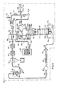
- Figure 6 is a schematic view of the flushing and recirculation systems of the invention.
- With reference now to Figures 1 and 2, wherein like numerals designate like components throughout all of the several figures, the system and method of the invention are both particularly adapted for assisting a pressure pulse cleaning system in removing sludge which accumulates within a nuclear steam generator 1. But before the application of the invention can be fully appreciated, some understanding of the general structure and the maintenance problems associated with such steam generators 1 is necessary.
- Nuclear steam generator 1 generally includes a
primary side 3 and asecondary side 5 which are hydraulically isolated from one another by atubesheet 7. Theprimary side 3 is bowl-shaped, and is divided into two, hydraulically isolated halves by means of adivider plate 8. One of the halves of theprimary side 3 includes a water inlet 9 for receiving hot, radioactive water that has been circulated through the core barrel of a nuclear reactor (not shown), while the other half includes awater outlet 13 for discharging this water back to the core barrel. This hot, radioactive water circulates through the U-shapedheat exchanger tubes 22 contained within thesecondary side 5 of the steam generator 1 from the inlet half of theprimary side 3 to the outlet half (see flow arrows). In the art, the water-receiving half of theprimary side 3 is called theinlet channel head 15, while the water-discharging half is called theoutlet channel head 17. - The
secondary side 5 of the steam generator 1 includes anelongated tube bundle 20 formed from approximately 3500 U-shapedheat exchanger tubes 22. Each of theheat exchanger tubes 22 includes ahot leg 24, aU-bend 26 at its top, and acold leg 28. The bottom end of the hot andcold legs heat exchanger tube 22 is securely mounted within bores in thetubesheet 7, and each of these legs terminates in an open end. the open ends of all thehot legs 24 communicate with theinlet channel head 15, while the open ends of all of thecold legs 28 communicate with theoutlet channel head 17. As will be better understood presently, heat from the water in theprimary side 3 circulating within the U-shapedheat exchanger tues 22 is transferred to nonradioactive feed water in thesecondary side 5 of the generator 1 in order to generate nonradioactive steam. - With reference now to Figures 2, 3A, 3B and 3C,
support plates 30 are provided to securely mount and uniformly space theheat exchanger tubes 22 within thesecondary side 5. Each of thesupport plates 30 includes a plurality ofbores 32 which are only slightly larger than the outer diameter of theheat exchanger tubes 22 extending therethrough. To facilitate a vertically-oriented circulation of the nonradioactive water within thesecondary side 5, a plurality ofcirculation ports 34 is also provided in each of thesupport plates 30. Small annular spaces orcrevices 37 exist between the outer surface of theheat exchanger tubes 22, and the inner surface of thebores 32. Although not specifically shown in any of the several figures, similarannular crevices 37 exist between the lower ends of both the hot andcold legs heat exchanger tubes 22, and the bores of thetubesheet 7 in which they are mounted. In some types of nuclear steam generators, the openings in thesupport plates 30 are not circular, but instead are trifoil or quatrefoil-shaped as is illustrated in Figures 4A and 4B. Insuch support plates 30, theheat exchanger tubes 22 are supported along either three or four equidistally spaced points around their circumferences. Because such broachedopenings 38 leave relatively large gaps at some points between theheat exchanger tubes 22 and thesupport plate 30, there is no need forseparate circulation ports 34. - With reference back to Figures 1 and 2, the top portion of the
secondary side 5 of the steam generator 1 includes asteam drying assembly 44 for extracting the water out of the wet steam produced when theheat exchanger tubes 22 boil the nonradioactive water within thesecondary side 5. Thesteam drying assembly 44 includes aprimary separator bank 46 formed from a battery of swirl vane separators, as well as asecondary separator bank 48 that includes a configuration of vanes that define a tortuous path for moisture-laden steam to pass through. Asteam outlet 49 is provided over thesteam drying assembly 44 for conducting dried steam to the blades of a turbine coupled to an electrical generator. The upper portion of thesecondary side 5 includes a pair of opposingmanways separator bank 48. The middle portion of thesecondary side 5 contains atube wrapper 52 that is disposed between thetube bundle 22 and the outer shell of the steam generator 1 in order to provide a downcomer path for water extracted from the wet steam that rises through thesteam drying assembly 44. - At the lower portion of the
secondary side 5, a pair of opposingsludge lance ports tubesheets 7 during the operation of the generator 1. These opposingsludge lance ports cold legs heat exchanger tubes 22. It should be noted that in some steam generators, the sludge lance ports are not oppositely disposed 180 degrees from one another, but are only 90 degrees apart. Moreover, in other steam generators, only one such sludge lance port is provided. In the steam generator arts, the elongated areas between rows oftubes 22 on thetubesheet 7 are known as tube lanes 54, while the relatively wider, elongated area between the hot and cold legs of the most centrally-disposedheat exchanger tubes 22 is known as thecentral tube lane 55. These tube lanes 54 are typically an inch or two wide in steam generators whosetubes 22 are arranged in a square pitch, such as that shown in Figures 3A, 3B and 3C. Narrower tube lanes 54 are present in steam generators whoseheat exchanger tubes 22 are arranged in a denser, triangular pitch such as shown in Figures 4A and 4B. Acentral tube lane 55 that is wider than the other tube lanes 54 is disposed between thesludge lance ports - During the operation of such steam generators 1, it has been observed that the inability of secondary-side water to circulate as freely in the
narrow crevices 37 orgaps 38 between theheat exchanger tubes 22, and thesupport plates 30 andtubesheets 7 can cause the nonradioactive water in these regions to boil completely out of these small spaces, a phenomenon which is known as "dry boiling". When such dry boiling occurs, any impurities in the secondary side water are deposited in thesenarrow crevices 37 orgaps 38. Such solid deposits tend to impede the already limited circulation of secondary side water through thesecrevices 37 andgaps 38 even more, thereby promoting even more dry boiling. This generates even more deposits in these regions and is one of the primary mechanisms for the generation of sludge which accumulates over the top of thetubesheet 7. Often the deposits created by such dry boiling are formed from relatively hard compounds of limited solubility, such as magnetite, which tends to stubbornly lock itself in suchsmall crevices 37 andgaps 38. These deposits have been known to wedge themselves so tightly in thecrevices 37 orgaps 38 between theheat exchanger tubes 22 and thebores 32 of thesupport plates 30 that thetube 22 can actually become dented in this region. - To remove these deposits, a pressure pulse cleaning system may be provided which comprises a pair of pressure
pulse generator assemblies 60b having nozzles 62 mounted in the twosludge lance ports flange 63 that allows it to be firmly secured over itsrespective port secondary side 5 is filled with enough demineralized water to at least cover thetubesheet 7, the lower ends of theheat exchanger tubes 22, and thenozzles 62 of the pressurepulse generator assemblies pressure pulse generators secondary side 5. These shock waves loosen sludge and debris from the upper surface of thetubesheet 7, and even more importantly from thecrevices 37 orgaps 38 between theexchanger tubes 22 and thebores 32 of thesupport plates 30. - The instant invention is both a system 70 (see Fig. 6) and method for flushing the loosened sludge and debris completely out of the interior of the
secondary side 5. - With reference now to Figures 3A and 6, the system of the invention comprises a vertical flush and recirculation system 70 for both draining and filling the
secondary side 5 with clean, deionized water while vertically flushing thetube bundle 28 and thetubesheet 7 with a forceful spray of water. As is best seen in Figure 3A, the system 70 includes a pair ofsuction hoses flange 63 of each of the pressurepulse generator assemblies suction nozzles tubesheet 7.Nozzles 74a and 74c are aligned along the periphery of thetubesheet 7 whilenozzle 74b is aligned along thecentral tube lane 55 in order to rapidly draw off water from a broad section of the top surface of thetubesheet 7. Each of thenozzles - As is best seen in Figure 6, the proximal ends of each of the
suction hoses diaphragm pump 76 by way ofconduit 78. The use of a diaphragm-type pump 76 is preferred at this point in the flushing and recirculation system 70 since the water withdrawn through thesuction hoses diaphragm pump 76 is in turn serially connected first to atranquilizer 80 and then aflow meter 82. Thetranquilizer 80 "evens out" the pulsations of water created by thediaphragm pump 76 and thus allows theflow meter 82 to display the average rate of the water flow out of thediaphragm pump 76. The output of theflow meter 82 is connected to the inlet of asurge tank 84 viaconduit 86. In the preferred embodiment, thesurge tank 84 has an approximately 1200 liter (300 gallon) capacity. The outlet of thesurge tank 84 is connected to the inlet of aflow pump 88 by way of asingle conduit 90, while the output of thepump 88 is connected to the inlet of acyclone separator 92 viaconduit 94. In operation, thesurge tank 84 accumulates the flow of water generated by thediaphragm pump 76 and smoothly delivers this water to the inlet of thepump 88. Thepump 88 in turn generates a sufficient pressure head in the recirculating water so that a substantial portion of the sludge suspended in the water will be centrifugally flung out of the water as it flows through thecyclone separator 92. - Located downstream of the
cyclone separator 92 is a 0.0001 to 0.0003 cm (one to three micron)bag filter 96 that is serially connected to a 0.0001 cm (one micron)cartridge filter 98. Thesefilters cyclone separator 92. Downstream of thefilters supply tank 100 that is connected to the outlet offilter 98 byconduit 102.Supply tank 100 is connected to anoutlet conduit 102 that leads to the inlet of anotherflow pump 104. The outlet of theflow pump 104 is in turn connected to the inlet of ade-mineralizer bed 106 by way ofconduit 108. The purpose of theflow pump 104 is to establish enough pressure in the recirculating water so that it flows through the serially connected ion exchange columns (not shown) in thedemineralizer bed 106 at an acceptably rapid flow rate. To this end, the power capacity offlow pump 104 is preferably somewhere between 203 and 406 hp (metric). The purpose of thedemineralizer bed 106 is to remove all ionic species from the water so that they will have no opportunity to re-enter thesecondary side 5 of the generator 1 and create new sludge deposits. - Located downstream of the
demineralizer bed 106 is a first T-joint 110 whose inlet is connected toconduit 112 as shown. Anisolation valve 114 and adrain valve 116 are located downstream of the two outlets of the T-joint 110 as shown to allow the water used in the cleaning method to be drained into the decontamination facility of the utility. Located downstream of the T-joint 110 is another T-joint 118 whose inlet is also connected toconduit 112 as shown.Diverter valves 120a and 120b are located downstream of the outlet of T-joint 110 as indicated. Normally valve 120a is open andvalve 120b is closed. However, if one desires to fill a second steam generator with the filtered and polished water drained from a first steam generator in order to expedite the pressure pulse cleaning method,valves 120a and 120b can be partially closed and partially opened, respectively. Flow meters 122a, 122b are located downstream of thevalves 120a and 120b so that an appropriate bifurcation of the flow fromconduit 112 can be had to effect such a simultaneous drain-fill step. Additionally, the conduit thatvalve 120b and flowmeter 122b are mounted in terminates in a quick-connect coupling 124. To expedite such a simultaneous drain-fill step,valves 120a and 120b are mounted on a wheeled cart (not shown) andconduit 112 is formed from a flexible hose to form a portable coupling station. - Downstream of the portable coupling station,
inlet conduit 112 terminates in the inlet of a T-joint 126 that bifurcates the inlet flow of water betweeninlet conduits Inlet conduits flowmeters 130a, 130b to help the system operator adjustflow valves 132a, 132b so that the flow of water fromconduit 112 is evenly divided throughinlet conduits inlet conduits manways flexible spray nozzles 134a,b and 136a,b, respectively. theflexible nozzles 134a,b and 136a,b extend through theprimary separator bank 46 so that their open distal ends are suspended over the tube bundle 20 a distance of about 15.72-26.20 cm (6-10 inches). In the preferred embodiment, the fournozzles 134a,b and 136a,b are roughly arranged in a square configuration over thetube bundle 20 so that the streams of water discharged therefrom uniformly strike the top portion of thetube bundle 20. To minimize back pressure, thenozzles 134a,b and 136a,b are 4.0-5.25 cm (1.5-2.0 inches) in diameter. Additionally, thenozzles 134a,b and 136a,b are each formed from a conduit material that is flexible enough so that the reaction forces generated by the pressurized streams of water discharged from its open distal end causes it to whip around in a more or less random pattern, which in turn renders the distribution of sprayed water even more uniform over the top of thetube bundle 20. - Water is initially supplied to the flushing and recirculation system 70 through
deionized water supply 140, which may be the deionized water reservoir of the utility being serviced.Water supply 140 includes anoutlet conduit 142 connected to the inlet of anotherflow pump 144. The outlet of theflow pump 144 is connected to anotherconduit 146 whose outlet is in turn connected to thesupply tank 100. Acheck valve 148 is provided inconduit 146 to insure that water from thesupply tank 100 cannot back up into thedeionized water supply 140. - In the first step of the method of the invention, the flushing and recirculation system 70 illustrated in Figure 6 is installed onto the
secondary side 5 of a nuclear steam generator 1. This is accomplished by bolting the mountingflanges 63 of thepressure pulse generators sludge lancing ports secondary side 5. This has the effect of positioning thesuction nozzles pressure pulse generator nozzles 74a and 74c are oriented along the periphery of thetubesheet 7 inside of thetube wrapper 52, andnozzle 74b is oriented along themain tube lane 55. At the same time, the outlet ends of theflexible spray nozzles 134a,b and 136a,b are manipulated into the position illustrated in Figure 1, wherein each of these nozzles is suspended less than 30 cm (a foot) above the upper end of thetube bundle 20. thesespray nozzles 134a,b and 136a,b are secured in place when the special manway covers 50.5a, 50.5b that include the previously mentioned manifolds are secured over themanways - In the next step of the method,
flow pump 144 is actuated to fillsupply tank 100 with purified and deionized water fromwater supply 140. Aftersupply tank 100 has been filled with a sufficient amount of water from thewater supply 140,flow pump 104 is actuated withvalves 114 and 120a open andvalve 120b closed in order to introduce this deionized water into theinlet conduits flow valves 132a and 132b are adjusted so that the flow through each of theseconduits flexible spray nozzles 134a,b and 136a,b, which in turn flows through thetube bundle 20 andsupport plates 30 and collects over the top surface of thetubesheet 7. When sufficient water has collected within thesecondary side 5 so that thenozzles 62 of each of thepressure pulse generators tubesheet 7 in the lower ends of theheat exchanger tubes 22, thereby loosening sludge and debris that has collected thereon. - Soon after
pressure pulse generators diaphragm pump 76 is started so that thesuction nozzles suction hoses secondary side 5. In the preferred method of the invention, thediaphragm pump 76 pulls out approximately 160 liters of water per minute from each of thesuction hoses flow pump 104 is adjusted so that each of theinlet conduits flexible spray nozzles 134a,b and 136a,b. The vertical flushing action of the water sprayed over the top of thetube bundle 20 and downwardly into thetubesheet 7 in combination with the suction afforded through thenozzle suction hoses pressure pulse generators - Since the flow rate of water through the
inlet conduits suction hoses secondary side 5 as thepressure pulse generators tubesheet 7, theheat exchanger tubes 22 and thesupport plates 30. In the preferred method of the invention, the flushing and recirculation system 70 continues to operate in this mode until thetube bundle 20 is completely submerged in water. Depending upon the amount of sludge that has accumulated in thesecondary side 5 of the steam generator 1 being cleaned, this step of the method of the invention may take anywhere between 12 and 20 hours. All during this step of the method, the sludge-containing water discharged through thesuction hoses cyclone separator 92, thefilter bag 96, thecartridge filter 98, and thedemineralizer bed 106 before being reintroduced into the steam generator 1 through theinlet conduits secondary side 5 is completely filled with water, the system 70 will contain approximately 80,000 liters of water, 72,000 of which is disposed within thesecondary side 5 of the steam generator 1, and 8,000 liters of which is in the pipelines and tanks of the balance of the flushing and recirculation system 70. - Once the
secondary side 5 is filled to the extent that the top of thetube bundle 20 is completely submerged in water, the operation of thediaphragm pump 76 is speeded up in order to increase the suction flow through thesuction hoses secondary side 5 to the rate at which water is introduced into thesecondary side 5 through the inlet conduits 28a and 28b. In this manner, the level of the water within thesecondary side 5 is maintained at equilibrium above thetube bundle 20 for preferably between 6 and 8 hours, during which time thepressure pulse generator inlet nozzles 134a,b and 136a,b causes the loosening and removal of a great deal of sludge from the interior of thesecondary side 5. - In the final step of the method of the invention, the water inside the
secondary side 5 of the steam generator 1 is slowly drained by reducing the flow of water through theinlet conduits secondary side 5. At the beginning of this step,diverter valve 120b is partially opened while diverter valve 120a is partially closed in order to divert some of the 80,000 liters of water which has accumulated into the system 70 back to the utility through quick disconnect coupling 124. - Like the previously described secondary side filling step, this draining step lasts between
abut 12 and 20 hours, depending upon the condition of thesecondary side 5 of the steam generator 1. It is during this step that the forceful spray of water emitted by the fourspray nozzles 134a,b and 136a,b is the most effective in removing sludge from thetube bundle 20, as a great deal of the sludge has been loosened by the succession of shock waves generated by the succession of pressurized pulses of gas emitted by thepressure pulse generator nozzles 134a,b and 136a,b runs through the annular spaces andgaps heat exchanger tubes 22 and thebores 32 which surround them and thesupport plate 30, thereby effectively pushing this sludge and debris downwardly to the top surface of thetubesheet 7 where it is entrained and swept away by the water flowing through thesuction nozzles pressure pulse generators - When the level of water in the
secondary side 5 is no longer sufficient to cover thenozzles 62 of thepressure pulse generators generators secondary side 5 is then removed, and both thepressure pulse generators manways 
Claims (28)
- A method for loosening and removing sludge and debris from the interior of the vessel of a heat exchanger (1) having a top portion, a bottom portion and a secondary side (5) and that contains one or more heat exchanger components, said method including introducing a sufficient amount of liquid in said heat exchanger vessel (1) to submerge at least a portion of the interior thereof that includes some of said sludge, debris and heat exchanger components, and generating a succession of shock waves within the liquid to loosen said sludge and debris, characterized by the step of vertically flushing the interior of the vessel (1) while simultaneously introducing liquid into the top portion of said vessel (1).
- A method for loosening and removing sludge and debris as defined in claim 1, wherein said succession of shock waves continues to be generated within said liquid while the interior of the vessel (1) is vertically flushed.
- A method for loosening and removing sludge and debris as defined in claim 1, wherein the rate of suctioning off liquid out of the vessel (1) is substantially the same as the rate of introducing liquid into the vessel (1).
- A method for loosening and removing sludge and debris as defined in claim 1, wherein the same liquid suctioned off from the bottom portion of the vessel (1) is recirculated to the top portion of the vessel (1).
- A method for loosening and removing sludge and debris as defined in claim 4, further characterized by the step of removing substantially all of the sludge and debris entrained in the liquid suctioned off from the bottom portion of the vessel (1) before recirculating the liquid back through the top portion of the vessel (1).
- A method for loosening and removing sludge and debris as defined in claim 1, wherein the liquid introduced into the top portion of the vessel (1) is forcefully sprayed over the interior of the vessel (1).
- A method for loosening and removing sludge and debris as defined in claim 6, wherein said sprayed liquid is directed over said heat exchanger components to remove loosened sludge and debris from said components.
- A method for loosening and removing sludge and debris as defined in claim 1, wherein said heat exchanger vessel (1) is filled by introducing liquid into the top portion of the vessel (1) faster than said liquid is suctioned off from the bottom portion of said vessel (1).
- A method for loosening and removing sludge and debris as defined in claim 8, wherein said heat exchanger vessel (1) is drained after being filled by suctioning off liquid from the bottom portion of the vessel (1) faster than said liquid is introduced into the top portion of said vessel (1).
- A method for loosening and removing sludge and debris as defined in claim 8, wherein between about 70 to 90 percent of the liquid introduced into the top portion of the vessel (1) is removed by suctioning off said liquid from the bottom portion of the vessel (1).
- A method for loosening and removing sludge and debris as defined in claim 10, further characterized by generating a succession of pressure pulses within the liquid by means of pulses of pressurized gas to create shock waves that loosen sludge and debris.
- A method for loosening and removing sludge and debris as defined in claim 11, wherein said pulses of pressurized gas are introduced directly into said liquid, and said debris and sludge loosening shock waves are in the form of fountains of liquid erupting above the surface of the liquid that forcefully slap against the heat exchanger components.
- A method for loosening and removing sludge and debris as defined in claim 11, wherein said debris and sludge loosening shock waves are in the form of projectiles of liquid discharged below the surface of the liquid that impinge on the heat exchanger components within the secondary side (5) of the heat exchanger (1).
- A method for loosening and removing sludge and debris as defined in claim 11, wherein said pulses of pressurized gas are introduced directly into said liquid, and said debris and sludge loosening shock waves are in the form of omnidirectional shock waves of liquid located below the surface of the liquid that impinge on the heat exchanger components within the secondary side (5) of the heat exchanger (1).
- A method for loosening and removing sludge and debris as defined in claim 11, wherein the secondary side (5) of the heat exchanger (1) is filled with enough liquid to completely submerge the heat exchanger components by introducing liquid into the top portion of the secondary side (5) at a rate faster than said liquid is suctioned off from the bottom portion of the secondary side (5), and wherein said succession of pressure pulses continues to be introduced into said liquid as said secondary side (5) is filled.
- A method for loosening and removing sludge and debris as defined in claim 15, wherein the filling rate is between about 20 and 30 percent higher than said draining rate.
- A method for loosening and removing sludge and debris as defined in claim 15, wherein said secondary side (5) is filled at a rate of about 400 liters per minute and suctioned off at a rate of about 320 liters per minute.
- A method for loosening and removing sludge and debris as defined in claim 15, wherein the secondary side (5) of the heat exchanger (1) is drained after being filled with enough liquid to submerge said heat exchanger components by suctioning off liquid out of said secondary side (5) at a rate faster than said liquid is introduced into said secondary side (5), and wherein said succession of pressure pulses continues to be introduced into said liquid as said secondary side (5) is drained.
- A method for loosening and removing sludge and debris as defined in claim 18, wherein the suctioning rate is between about 20 and 30 percent higher than the rate at which liquid is introduced into the secondary side (5).
- A method for loosening and removing sludge and debris as defined in claim 18, wherein said secondary side (5) is suctioned off at a rate of about 400 liters per minute while liquid is introduced at a rate of about 320 liters per minute.
- A method for loosening and removing sludge and debris as defined in claim 11, wherein the same liquid suctioned off from the secondary side (5) is recirculated back through the top portion of the secondary side (5) after substantially all of the sludge and debris entrained in said liquid has been removed.
- A method for loosening and removing sludge and debris as defined in claim 11, wherein the liquid introduced into the top portion of the secondary side (5) is forcefully sprayed over the heat exchanger components to help remove loosened sludge and debris from said heat exchanger components.
- A method for loosening and removing sludge and debris as defined in claim 18, wherein said introducing rate exceeds said suctioning off rate for between about 12 and 20 hours, and said introducing rate substantially equals said suctioning off rate for between about six and eight hours, and said suctioning off rate exceeds said introducing rate for between about 12 and 20 hours.
- A method for loosening and removing sludge and debris as defined in claim 21, wherein substantially all ionic species dissolved in liquid drained from the bottom portion of the secondary side (5) is removed before the liquid is recirculated back through the upper portion of the secondary side (5).
- A system (70) for loosening and removing sludge and debris from the interior of the vessel of a heat exchanger (1) having top and bottom portions and containing one or more heat exchanger components immersed in a liquid, said system having means for generating a succession of pressure pulses to create shock waves in said liquid to loosen said sludge and debris, characterized by means (134a,b; 136a,b; 74a, 74b, 74c; 128a, 128b) for vertically flushing said heat exchanger components while said pressure pulse means (60a, 60b, 62) creates sludge loosening shock waves.
- A system (70) for loosening and removing sludge and debris as defined in claim 25, wherein said vertical flushing means (134a,b; 136a,b; 74a, 74b, 74c; 128a, 128b) is further characterized by a suction means for suctioning liquid out of the bottom portion of the vessel (1), and a nozzle means (50a, 50b) for introducing liquid into the top portion of the vessel (1) at the same time said suctioning means removes liquid from said vessel (1).
- A system for loosening and removing sludge and debris as defined in claim 25, wherein said vertical flushing means also functions to vary the level of liquid within said vessel (1).
- A system for loosening and removing sludge and debris as defined in claim 26, wherein said nozzle means (50a, 50b) forcefully sprays liquid over said heat exchanger components to remove sludge and debris loosened by said shock waves.
Applications Claiming Priority (2)
| Application Number | Priority Date | Filing Date | Title |
|---|---|---|---|
| US456436 | 1989-12-26 | ||
| US07/456,436 US5019329A (en) | 1989-12-26 | 1989-12-26 | System and method for vertically flushing a steam generator during a shock wave cleaning operation |
Publications (3)
| Publication Number | Publication Date |
|---|---|
| EP0435486A2 true EP0435486A2 (en) | 1991-07-03 |
| EP0435486A3 EP0435486A3 (en) | 1991-11-27 |
| EP0435486B1 EP0435486B1 (en) | 1994-07-27 |
Family
ID=23812761
Family Applications (1)
| Application Number | Title | Priority Date | Filing Date |
|---|---|---|---|
| EP90313255A Expired - Lifetime EP0435486B1 (en) | 1989-12-26 | 1990-12-06 | System and method for loosening and removing sludge and debris from the interior of a vessel of a heat exchanger |
Country Status (7)
| Country | Link |
|---|---|
| US (1) | US5019329A (en) |
| EP (1) | EP0435486B1 (en) |
| JP (1) | JPH03291496A (en) |
| KR (1) | KR910011346A (en) |
| CA (1) | CA2032756A1 (en) |
| DE (1) | DE69011067T2 (en) |
| ES (1) | ES2057447T3 (en) |
Cited By (5)
| Publication number | Priority date | Publication date | Assignee | Title |
|---|---|---|---|---|
| DE102008005668B3 (en) * | 2007-11-06 | 2009-04-02 | Areva Np Gmbh | Inner surface cleaning device for heat exchanger pipe of auxiliary heat exchanger in Canada deuterium uranium reactor facility, has inlet channel formed in area of expansion chamber to suck foreign gas |
| US8397770B2 (en) | 2009-01-28 | 2013-03-19 | Fuel Transfer Technologies | Non-overflow liquid delivery system |
| CN106247845A (en) * | 2015-06-10 | 2016-12-21 | 阿海珐有限公司 | For cleaning equipment and the method for heat exchanger interior zone |
| US10502510B2 (en) | 2016-02-09 | 2019-12-10 | Babcock Power Services, Inc. | Cleaning tubesheets of heat exchangers |
| EP3819915A4 (en) * | 2018-07-06 | 2022-04-06 | Korea Hydro & Nuclear Power Co., Ltd | Apparatus for treating waste of nuclear reactor pressure vessel, and method for treating waste of nuclear reactor pressure vessel |
Families Citing this family (20)
| Publication number | Priority date | Publication date | Assignee | Title |
|---|---|---|---|---|
| FR2684433B1 (en) * | 1991-12-02 | 1994-01-07 | Framatome Sa | DEVICE FOR TRAPPING MIGRANT BODIES WITHIN THE SECONDARY CIRCUIT OF A STEAM GENERATOR. |
| US5413168A (en) * | 1993-08-13 | 1995-05-09 | Westinghouse Electric Corporation | Cleaning method for heat exchangers |
| US5913320A (en) * | 1995-04-11 | 1999-06-22 | Foster-Miller, Inc. | Sludge removal system |
| US5841826A (en) * | 1995-08-29 | 1998-11-24 | Westinghouse Electric Corporation | Method of using a chemical solution to dislodge and dislocate scale, sludge and other deposits from nuclear steam generators |
| US5764717A (en) * | 1995-08-29 | 1998-06-09 | Westinghouse Electric Corporation | Chemical cleaning method for the removal of scale sludge and other deposits from nuclear steam generators |
| US6718002B2 (en) * | 1997-05-21 | 2004-04-06 | Westinghouse Atom Ab | Method and device for removing radioactive deposits |
| US6050227A (en) * | 1998-01-15 | 2000-04-18 | Meylan Enterprises | Power plant boiler cleaner |
| US6178925B1 (en) * | 1999-09-29 | 2001-01-30 | Advanced Technology Materials, Inc. | Burst pulse cleaning method and apparatus for liquid delivery system |
| GB2358791A (en) * | 2000-02-04 | 2001-08-08 | Versar Inc | Method composition and apparatus for cleaning internal surfaces of oxygen converters and cylinders |
| US6740168B2 (en) | 2001-06-20 | 2004-05-25 | Dominion Engineering Inc. | Scale conditioning agents |
| US6797070B2 (en) * | 2001-07-17 | 2004-09-28 | John Darryl Boyce | Method for cleaning a cooler apparatus |
| KR101213379B1 (en) * | 2004-04-01 | 2012-12-17 | 웨스팅하우스 일렉트릭 컴퍼니 엘엘씨 | Improved scale conditioning agents and treatment method |
| DE102004060884A1 (en) * | 2004-12-17 | 2006-06-29 | Clyde Bergemann Gmbh | Method for removing of combustion residues from wall of chamber carrying combustion gases involves contacting of combustion residues with first cleaning medium, and contacting of pre-treated residues with second cleaning medium |
| US9228575B2 (en) * | 2010-11-16 | 2016-01-05 | Zoeller Pump Company, Llc | Sealed and self-contained tankless water heater flushing system |
| US9791145B2 (en) * | 2013-03-14 | 2017-10-17 | Westinghouse Electric Company Llc | Method and apparatus for manipulating equipment inside a steam generator |
| US20150029340A1 (en) * | 2013-07-26 | 2015-01-29 | JVC Kenwood Corporation | Water droplet removal apparatus and camera apparatus |
| WO2016014095A1 (en) * | 2014-07-23 | 2016-01-28 | Westinghouse Electric Company Llc | Method and apparatus for manipulating equipment inside a steam generator |
| US11371788B2 (en) * | 2018-09-10 | 2022-06-28 | General Electric Company | Heat exchangers with a particulate flushing manifold and systems and methods of flushing particulates from a heat exchanger |
| CN110822406B (en) * | 2019-11-20 | 2021-05-14 | 苏州热工研究院有限公司 | Full-tube-bundle leaching system and leaching method for steam generator |
| EP4328520A1 (en) * | 2022-08-25 | 2024-02-28 | ERK Eckrohrkessel GmbH | Method and device for using geothermal heat |
Citations (3)
| Publication number | Priority date | Publication date | Assignee | Title |
|---|---|---|---|---|
| US4645542A (en) * | 1984-04-26 | 1987-02-24 | Anco Engineers, Inc. | Method of pressure pulse cleaning the interior of heat exchanger tubes located within a pressure vessel such as a tube bundle heat exchanger, boiler, condenser or the like |
| US4699665A (en) * | 1984-12-26 | 1987-10-13 | Anco Engineers, Inc. | Method of pressure pulse cleaning heat exchanger tubes, upper tube support plates and other areas in a nuclear steam generator and other tube bundle heat exchangers |
| EP0339289A1 (en) * | 1988-04-19 | 1989-11-02 | Westinghouse Electric Corporation | Improved pressure pulse cleaning method |
Family Cites Families (12)
| Publication number | Priority date | Publication date | Assignee | Title |
|---|---|---|---|---|
| US2716021A (en) * | 1952-12-22 | 1955-08-23 | Babcock & Wilcox Co | Method of and damper apparatus for cleaning tube banks |
| US3913531A (en) * | 1974-06-20 | 1975-10-21 | Combustion Eng | Sediment blowdown arrangement for a shell and tube vapor generator |
| GB1509204A (en) * | 1974-11-14 | 1978-05-04 | Leslie Co | Self-cleaning heat exchanger circuit |
| US4079701A (en) * | 1976-05-17 | 1978-03-21 | Westinghouse Electric Corporation | Steam generator sludge removal system |
| US4655846A (en) * | 1983-04-19 | 1987-04-07 | Anco Engineers, Inc. | Method of pressure pulse cleaning a tube bundle heat exchanger |
| US4566406A (en) * | 1983-07-13 | 1986-01-28 | Westinghouse Electric Corp. | Sludge removing apparatus for a steam generator |
| US4620881A (en) * | 1983-08-26 | 1986-11-04 | Innus Industrial Nuclear Services S.A. | Method for cleaning a steam generator |
| DE3423619C2 (en) * | 1984-06-27 | 1986-09-04 | Balcke-Dürr AG, 4030 Ratingen | Device for cleaning the heat-exchanging surfaces of the storage masses of regenerative heat exchangers |
| US4756770A (en) * | 1986-02-11 | 1988-07-12 | Arkansas Power And Light Company | Water slap steam generator cleaning method |
| US4905900A (en) * | 1986-08-29 | 1990-03-06 | Anco Engineers, Inc. | Water cannon apparatus for cleaning a tube bundle heat exchanger, boiler, condenser, or the like |
| US4773357A (en) * | 1986-08-29 | 1988-09-27 | Anco Engineers, Inc. | Water cannon apparatus and method for cleaning a tube bundle heat exchanger, boiler, condenser, or the like |
| US4899697A (en) * | 1988-04-19 | 1990-02-13 | Westinghouse Electric Corp. | Pressure pulse cleaning apparatus |
-
1989
- 1989-12-26 US US07/456,436 patent/US5019329A/en not_active Expired - Lifetime
-
1990
- 1990-12-06 EP EP90313255A patent/EP0435486B1/en not_active Expired - Lifetime
- 1990-12-06 ES ES90313255T patent/ES2057447T3/en not_active Expired - Lifetime
- 1990-12-06 DE DE69011067T patent/DE69011067T2/en not_active Expired - Fee Related
- 1990-12-21 CA CA002032756A patent/CA2032756A1/en not_active Abandoned
- 1990-12-24 KR KR1019900021688A patent/KR910011346A/en not_active Application Discontinuation
- 1990-12-26 JP JP2406747A patent/JPH03291496A/en active Pending
Patent Citations (3)
| Publication number | Priority date | Publication date | Assignee | Title |
|---|---|---|---|---|
| US4645542A (en) * | 1984-04-26 | 1987-02-24 | Anco Engineers, Inc. | Method of pressure pulse cleaning the interior of heat exchanger tubes located within a pressure vessel such as a tube bundle heat exchanger, boiler, condenser or the like |
| US4699665A (en) * | 1984-12-26 | 1987-10-13 | Anco Engineers, Inc. | Method of pressure pulse cleaning heat exchanger tubes, upper tube support plates and other areas in a nuclear steam generator and other tube bundle heat exchangers |
| EP0339289A1 (en) * | 1988-04-19 | 1989-11-02 | Westinghouse Electric Corporation | Improved pressure pulse cleaning method |
Cited By (12)
| Publication number | Priority date | Publication date | Assignee | Title |
|---|---|---|---|---|
| DE102008005668B3 (en) * | 2007-11-06 | 2009-04-02 | Areva Np Gmbh | Inner surface cleaning device for heat exchanger pipe of auxiliary heat exchanger in Canada deuterium uranium reactor facility, has inlet channel formed in area of expansion chamber to suck foreign gas |
| US8397770B2 (en) | 2009-01-28 | 2013-03-19 | Fuel Transfer Technologies | Non-overflow liquid delivery system |
| US8408252B2 (en) | 2009-01-28 | 2013-04-02 | Fuel Transfer Technologies | Nozzle for use in a non-overflow liquid delivery system |
| US8474492B2 (en) | 2009-01-28 | 2013-07-02 | Fuel Transfer Technologies Inc. | Automatic shut-off nozzle for use in a non-overflow liquid delivery system |
| US8925595B2 (en) | 2009-01-28 | 2015-01-06 | Fuel Transfer Technologies Inc. | Nozzle for use in a non-overflow liquid delivery system |
| US8936051B2 (en) | 2009-01-28 | 2015-01-20 | Fuel Transfer Technologies Inc. | Non-overflow liquid delivery system |
| CN106247845A (en) * | 2015-06-10 | 2016-12-21 | 阿海珐有限公司 | For cleaning equipment and the method for heat exchanger interior zone |
| CN106247845B (en) * | 2015-06-10 | 2020-08-14 | 法马通有限公司 | Apparatus and method for cleaning the interior of a heat exchanger |
| US10502510B2 (en) | 2016-02-09 | 2019-12-10 | Babcock Power Services, Inc. | Cleaning tubesheets of heat exchangers |
| US11561054B2 (en) | 2016-02-09 | 2023-01-24 | Thermal Engineering International (Usa) Inc. | Cleaning tubesheets of heat exchangers |
| EP3819915A4 (en) * | 2018-07-06 | 2022-04-06 | Korea Hydro & Nuclear Power Co., Ltd | Apparatus for treating waste of nuclear reactor pressure vessel, and method for treating waste of nuclear reactor pressure vessel |
| US11682496B2 (en) | 2018-07-06 | 2023-06-20 | Korea Hydro & Nuclear Power Co., Ltd. | Apparatus for treating waste of nuclear reactor pressure vessel, and method for treating waste of nuclear reactor pressure vessel |
Also Published As
| Publication number | Publication date |
|---|---|
| CA2032756A1 (en) | 1991-06-27 |
| JPH03291496A (en) | 1991-12-20 |
| KR910011346A (en) | 1991-08-07 |
| DE69011067D1 (en) | 1994-09-01 |
| DE69011067T2 (en) | 1995-03-09 |
| ES2057447T3 (en) | 1994-10-16 |
| EP0435486B1 (en) | 1994-07-27 |
| US5019329A (en) | 1991-05-28 |
| EP0435486A3 (en) | 1991-11-27 |
Similar Documents
| Publication | Publication Date | Title |
|---|---|---|
| EP0435486B1 (en) | System and method for loosening and removing sludge and debris from the interior of a vessel of a heat exchanger | |
| US5092280A (en) | Pressure pulse cleaning apparatus | |
| EP0339289B1 (en) | Improved pressure pulse cleaning method | |
| EP0339288B1 (en) | Improved pressure pulse cleaning method | |
| US4492186A (en) | Steam generator sludge removal method | |
| US4645542A (en) | Method of pressure pulse cleaning the interior of heat exchanger tubes located within a pressure vessel such as a tube bundle heat exchanger, boiler, condenser or the like | |
| US4715324A (en) | Nuclear steam generator sludge lancing method and apparatus | |
| JPS6051001B2 (en) | Steam generator sludge removal method | |
| US5764717A (en) | Chemical cleaning method for the removal of scale sludge and other deposits from nuclear steam generators | |
| JPS58127003A (en) | Method and apparatus for removing sludge deposited onto pipe support plate of steam generator | |
| US5006304A (en) | Pressure pulse cleaning method | |
| EP0458533B1 (en) | Chemical cleaning method for steam generators utilizing pressure pulsing | |
| CA1216479A (en) | Process for cleaning a steam generator | |
| CA2369481C (en) | Descaling device for steam generator | |
| EP0440465A1 (en) | Method and apparatus for removing foreign matter from heat exchanger tubesheets | |
| US4848278A (en) | Nuclear steam generator sludge lancing method and apparatus | |
| JPS6173096A (en) | Contaminated deposit removing device | |
| EP0249480B1 (en) | Sludge lance wand | |
| US4769085A (en) | Method for cleaning a steam generator | |
| EP0422267B1 (en) | Improved pressure pulse cleaning method | |
| EP0484042B1 (en) | Method for removing sludge and deposits from the interior of a heat exchanger vessel | |
| EP0422266B1 (en) | Improved pressure pulse cleaning method | |
| JP3371270B2 (en) | Scum transfer collection device | |
| JP3371271B2 (en) | Scum collection device | |
| CN216523295U (en) | Plate heat exchanger not easy to scale |
Legal Events
| Date | Code | Title | Description |
|---|---|---|---|
| PUAI | Public reference made under article 153(3) epc to a published international application that has entered the european phase |
Free format text: ORIGINAL CODE: 0009012 |
|
| AK | Designated contracting states |
Kind code of ref document: A2 Designated state(s): BE DE ES FR GB IT SE |
|
| PUAL | Search report despatched |
Free format text: ORIGINAL CODE: 0009013 |
|
| AK | Designated contracting states |
Kind code of ref document: A3 Designated state(s): BE DE ES FR GB IT SE |
|
| 17P | Request for examination filed |
Effective date: 19920526 |
|
| 17Q | First examination report despatched |
Effective date: 19921215 |
|
| GRAA | (expected) grant |
Free format text: ORIGINAL CODE: 0009210 |
|
| AK | Designated contracting states |
Kind code of ref document: B1 Designated state(s): BE DE ES FR GB IT SE |
|
| ET | Fr: translation filed | ||
| REF | Corresponds to: |
Ref document number: 69011067 Country of ref document: DE Date of ref document: 19940901 |
|
| ITF | It: translation for a ep patent filed | ||
| REG | Reference to a national code |
Ref country code: ES Ref legal event code: FG2A Ref document number: 2057447 Country of ref document: ES Kind code of ref document: T3 |
|
| EAL | Se: european patent in force in sweden |
Ref document number: 90313255.3 |
|
| PLBE | No opposition filed within time limit |
Free format text: ORIGINAL CODE: 0009261 |
|
| STAA | Information on the status of an ep patent application or granted ep patent |
Free format text: STATUS: NO OPPOSITION FILED WITHIN TIME LIMIT |
|
| 26N | No opposition filed | ||
| PGFP | Annual fee paid to national office [announced via postgrant information from national office to epo] |
Ref country code: GB Payment date: 19971107 Year of fee payment: 8 |
|
| PGFP | Annual fee paid to national office [announced via postgrant information from national office to epo] |
Ref country code: SE Payment date: 19971202 Year of fee payment: 8 |
|
| PGFP | Annual fee paid to national office [announced via postgrant information from national office to epo] |
Ref country code: FR Payment date: 19971203 Year of fee payment: 8 |
|
| PGFP | Annual fee paid to national office [announced via postgrant information from national office to epo] |
Ref country code: ES Payment date: 19971216 Year of fee payment: 8 |
|
| PGFP | Annual fee paid to national office [announced via postgrant information from national office to epo] |
Ref country code: DE Payment date: 19971229 Year of fee payment: 8 |
|
| PGFP | Annual fee paid to national office [announced via postgrant information from national office to epo] |
Ref country code: BE Payment date: 19980115 Year of fee payment: 8 |
|
| PG25 | Lapsed in a contracting state [announced via postgrant information from national office to epo] |
Ref country code: GB Free format text: LAPSE BECAUSE OF NON-PAYMENT OF DUE FEES Effective date: 19981206 |
|
| PG25 | Lapsed in a contracting state [announced via postgrant information from national office to epo] |
Ref country code: SE Free format text: LAPSE BECAUSE OF NON-PAYMENT OF DUE FEES Effective date: 19981207 |
|
| PG25 | Lapsed in a contracting state [announced via postgrant information from national office to epo] |
Ref country code: BE Free format text: LAPSE BECAUSE OF NON-PAYMENT OF DUE FEES Effective date: 19981231 |
|
| BERE | Be: lapsed |
Owner name: WESTINGHOUSE ELECTRIC CORP. Effective date: 19981231 |
|
| GBPC | Gb: european patent ceased through non-payment of renewal fee |
Effective date: 19981206 |
|
| PG25 | Lapsed in a contracting state [announced via postgrant information from national office to epo] |
Ref country code: FR Free format text: LAPSE BECAUSE OF NON-PAYMENT OF DUE FEES Effective date: 19990831 |
|
| REG | Reference to a national code |
Ref country code: FR Ref legal event code: ST |
|
| PG25 | Lapsed in a contracting state [announced via postgrant information from national office to epo] |
Ref country code: DE Free format text: LAPSE BECAUSE OF NON-PAYMENT OF DUE FEES Effective date: 19991001 |
|
| PG25 | Lapsed in a contracting state [announced via postgrant information from national office to epo] |
Ref country code: ES Free format text: LAPSE BECAUSE OF NON-PAYMENT OF DUE FEES Effective date: 19991207 |
|
| REG | Reference to a national code |
Ref country code: ES Ref legal event code: FD2A Effective date: 20000114 |
|
| PG25 | Lapsed in a contracting state [announced via postgrant information from national office to epo] |
Ref country code: IT Free format text: LAPSE BECAUSE OF NON-PAYMENT OF DUE FEES;WARNING: LAPSES OF ITALIAN PATENTS WITH EFFECTIVE DATE BEFORE 2007 MAY HAVE OCCURRED AT ANY TIME BEFORE 2007. THE CORRECT EFFECTIVE DATE MAY BE DIFFERENT FROM THE ONE RECORDED. Effective date: 20051206 |