EP0435446A2 - Corrugated mold block - Google Patents
Corrugated mold block Download PDFInfo
- Publication number
- EP0435446A2 EP0435446A2 EP90312725A EP90312725A EP0435446A2 EP 0435446 A2 EP0435446 A2 EP 0435446A2 EP 90312725 A EP90312725 A EP 90312725A EP 90312725 A EP90312725 A EP 90312725A EP 0435446 A2 EP0435446 A2 EP 0435446A2
- Authority
- EP
- European Patent Office
- Prior art keywords
- sub
- blocks
- vacuum
- block
- corrugated
- Prior art date
- Legal status (The legal status is an assumption and is not a legal conclusion. Google has not performed a legal analysis and makes no representation as to the accuracy of the status listed.)
- Granted
Links
- 238000000465 moulding Methods 0.000 claims abstract description 10
- 238000000034 method Methods 0.000 claims description 5
- 238000004519 manufacturing process Methods 0.000 claims description 4
- 238000005266 casting Methods 0.000 claims description 2
- 239000002184 metal Substances 0.000 claims description 2
- 229920001169 thermoplastic Polymers 0.000 description 7
- 239000004416 thermosoftening plastic Substances 0.000 description 7
- 230000013011 mating Effects 0.000 description 2
- 230000001939 inductive effect Effects 0.000 description 1
Images



Classifications
-
- B—PERFORMING OPERATIONS; TRANSPORTING
- B29—WORKING OF PLASTICS; WORKING OF SUBSTANCES IN A PLASTIC STATE IN GENERAL
- B29C—SHAPING OR JOINING OF PLASTICS; SHAPING OF MATERIAL IN A PLASTIC STATE, NOT OTHERWISE PROVIDED FOR; AFTER-TREATMENT OF THE SHAPED PRODUCTS, e.g. REPAIRING
- B29C33/00—Moulds or cores; Details thereof or accessories therefor
- B29C33/10—Moulds or cores; Details thereof or accessories therefor with incorporated venting means
-
- B—PERFORMING OPERATIONS; TRANSPORTING
- B29—WORKING OF PLASTICS; WORKING OF SUBSTANCES IN A PLASTIC STATE IN GENERAL
- B29C—SHAPING OR JOINING OF PLASTICS; SHAPING OF MATERIAL IN A PLASTIC STATE, NOT OTHERWISE PROVIDED FOR; AFTER-TREATMENT OF THE SHAPED PRODUCTS, e.g. REPAIRING
- B29C2791/00—Shaping characteristics in general
- B29C2791/004—Shaping under special conditions
- B29C2791/006—Using vacuum
Definitions
- the present invention relates to mold blocks, and more particularly to mold blocks which circulate about an endless path to vacuum form corrugated tubes.
- a well known method for manufacturing corrugated pipes is to extrude a tube of thermoplastic from a head and then conform that tube to the interior of a corrugated mold tunnel formed by mold blocks.
- the mold blocks typically come in pairs and mate together to form a portion of the mold tunnel, and the thermoplastic is either blown into its shape (by pressure created within the mold tunnel) or by vacuum (where vacuum draws the air from around the mold tunnel).
- a corrugated mold block for a vacuum machine for molding corrugated tubes is formed of a plurality of sub-blocks rigidly secured end to end.
- Each sub-block has an arcuate face which is corrugated with not more than one complete wavelength of circumferential grooves and lands, and two longitudinally spaced end surfaces.
- a vacuum channel is provided about one of the end surfaces of each sub-block, and openings in each sub-block connect the channel and the face.
- a method of making a corrugated mold block comprising the steps of: (1) casting a plurality of metal sub-blocks each having a face substantially arcuate about a longitudinal axis and corrugated with not more than one complete wavelength of circumferential grooves and lands, two longitudinally spaced end surfaces, a vacuum channel about one of the end surfaces open to the outside of the sub-block, and openings between the face and the channel; (2) aligning the formed sub-blocks longitudinally with end surfaces abutting and their faces forming a semicircular, longitudinally disposed continuous corrugation; and (3) rigidly securing the aligned sub-blocks together.
- a pair of mating mold blocks 10 is shown in perspective in Fig. 1.
- each mold block forms a portion of a mold tunnel 12 about a longitudinal axis 14.
- two mold blocks would be circulated about an endless track or path with the mold blocks 10 separated as the blocks pass an extruder head (which dispenses heated, thermoplastic in a cylindrical fashion).
- the mold blocks 10 are then brought together as shown in Fig. 1 to define the mold tunnel 12 (together with adjacent pairs of mold blocks), and a vacuum draws the thermoplastic against the walls of the mold tunnel 12 to form the corrugated tube or pipe.
- the two mold blocks 10 could be carried about one track pivotally by a single carriage in a clam shell type of operation such as shown in U.S. Patent No. 4,439,130, or alternatively the mold blocks 10 could be used in a system such as that shown in U.S. Patent No. 4,319,872, with the two mold blocks of each pair carried on opposite endless tracks, mated together along a portion of the tracks to form a mold tunnel.
- the mold block 10 comprises a plurality of adjacent sub-blocks 16 adjoined so as to define a continuous corrugated surface 18 with alternating grooves 20 and lands 22 and substantially arcuate 180 degrees about the longitudinal axis 14 (see Fig. 1).
- the grooves 20 and lands 22 of each sub-block extend up to one complete wavelength (i.e., the width of one groove 20 and one land 22), so that when together, the mold block face defines a continuous corrugated surface through the mold tunnel 12.
- a plurality of slits 34 are disposed at the grooves 20 of the sub-blocks 16 and are connected to a plurality of vacuum ports 36.
- the ports 36 are in turn in communication with semicircular grooves 38 cast in the end faces 24, 26 of each sub-block 16 which, when the sub-blocks 16 are secured together as described above define a continuous circular vacuum passage 40.
- a similar vacuum passage 40 is created between the adjacent mold blocks 10.
- the present invention could similarly be practiced through the use of selected longitudinal bores through the sub-blocks in order to connect a couple of the vacuum passages so that only one vacuum channel to the header need be provided for the connected passages.
Landscapes
- Engineering & Computer Science (AREA)
- Mechanical Engineering (AREA)
- Moulds For Moulding Plastics Or The Like (AREA)
- Blow-Moulding Or Thermoforming Of Plastics Or The Like (AREA)
- Laminated Bodies (AREA)
Abstract
Description
- The present invention relates to mold blocks, and more particularly to mold blocks which circulate about an endless path to vacuum form corrugated tubes.
- A well known method for manufacturing corrugated pipes is to extrude a tube of thermoplastic from a head and then conform that tube to the interior of a corrugated mold tunnel formed by mold blocks. The mold blocks typically come in pairs and mate together to form a portion of the mold tunnel, and the thermoplastic is either blown into its shape (by pressure created within the mold tunnel) or by vacuum (where vacuum draws the air from around the mold tunnel).
- Structures which have been used in the vacuum method of manufacture are illustrated in U.S. Pat. Nos. 4,318,872, 4,439,130, and 4,718,844. These patents all address the problem of drawing a uniform, strong vacuum around the entirety of the mold blocks which are continually moving during the molding process. As can be seen from these structures, it is difficult to inexpensively form any such mold block.
- In one aspect of the present invention, a corrugated mold block for a vacuum machine for molding corrugated tubes is formed of a plurality of sub-blocks rigidly secured end to end. Each sub-block has an arcuate face which is corrugated with not more than one complete wavelength of circumferential grooves and lands, and two longitudinally spaced end surfaces. A vacuum channel is provided about one of the end surfaces of each sub-block, and openings in each sub-block connect the channel and the face. When the sub-blocks are secured together into a mold block (and when mold blocks abut during molding), the vacuum channels and openings together define vacuum passages for each of the corrugation grooves, which passages are all connected to a vacuum source for drawing a vacuum during molding.
- In another aspect of the present invention, a method of making a corrugated mold block is described, comprising the steps of: (1) casting a plurality of metal sub-blocks each having a face substantially arcuate about a longitudinal axis and corrugated with not more than one complete wavelength of circumferential grooves and lands, two longitudinally spaced end surfaces, a vacuum channel about one of the end surfaces open to the outside of the sub-block, and openings between the face and the channel; (2) aligning the formed sub-blocks longitudinally with end surfaces abutting and their faces forming a semicircular, longitudinally disposed continuous corrugation; and (3) rigidly securing the aligned sub-blocks together.
- It is an object of the present invention to provide a mold block adapted to draw a strong and uniform vacuum about the mold tunnel in order to properly conform the thermoplastic to the desired corrugated tubular shape, while at the same time minimizing the complexity and cost of the mold block.
-
- Fig. 1 is a perspective view of a pair of mold blocks embodying the present invention;
- Fig. 2 is a top view of a mold block embodying the present invention;
- Fig. 3 is a sectional view of a mold block embodying the present invention;
- Fig. 4 is an exploded sectional view of two sub-blocks embodying the present invention; and
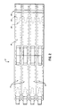
- Fig. 5 is a side view of a mold block embodying the present invention.
- A pair of
mating mold blocks 10 is shown in perspective in Fig. 1. When together as shown in Fig. 1, each mold block forms a portion of amold tunnel 12 about alongitudinal axis 14. With the embodiment illustrated in Fig. 1, two mold blocks would be circulated about an endless track or path with themold blocks 10 separated as the blocks pass an extruder head (which dispenses heated, thermoplastic in a cylindrical fashion). Themold blocks 10 are then brought together as shown in Fig. 1 to define the mold tunnel 12 (together with adjacent pairs of mold blocks), and a vacuum draws the thermoplastic against the walls of themold tunnel 12 to form the corrugated tube or pipe. - It should be noted that the two
mold blocks 10 could be carried about one track pivotally by a single carriage in a clam shell type of operation such as shown in U.S. Patent No. 4,439,130, or alternatively themold blocks 10 could be used in a system such as that shown in U.S. Patent No. 4,319,872, with the two mold blocks of each pair carried on opposite endless tracks, mated together along a portion of the tracks to form a mold tunnel. - Reference will now be made to the detailed structure of a
mold block 10 of the present invention. Though only onemold block 10 will be described, it should be understood that theother mold block 10 in each pair will be identical to (and turned 180 degrees from) themold block 10 being described. - As best shown in Figs. 1-3, the
mold block 10 comprises a plurality ofadjacent sub-blocks 16 adjoined so as to define a continuouscorrugated surface 18 withalternating grooves 20 andlands 22 and substantially arcuate 180 degrees about the longitudinal axis 14 (see Fig. 1). Thegrooves 20 andlands 22 of each sub-block extend up to one complete wavelength (i.e., the width of onegroove 20 and one land 22), so that when together, the mold block face defines a continuous corrugated surface through themold tunnel 12. -
Adjacent sub-blocks 16 are mated at theirfront end face 24 and therear end face 26, respectively. Thesub-blocks 16 defining the mold block 10 (four such sub-blocks are shown in Fig. 3) are aligned by adowel 28 fitted intocountersunk fastener passageways 30 of each pair ofadjacent sub-blocks 16.Bolts 32 run coaxially through thedowels 28 the length of themold block 10, and secure thesub-blocks 16 together by tightening of thebolts 32 and nuts 33 (the nuts and bolt heads reside in the outer fastener passageways in the end sub-blocks 16). - A plurality of
slits 34 are disposed at thegrooves 20 of thesub-blocks 16 and are connected to a plurality ofvacuum ports 36. Theports 36 are in turn in communication withsemicircular grooves 38 cast in the end faces 24, 26 of eachsub-block 16 which, when thesub-blocks 16 are secured together as described above define a continuouscircular vacuum passage 40. Whenadjacent mold blocks 10 are closed, asimilar vacuum passage 40 is created between theadjacent mold blocks 10. - As will be understood by a skilled artisan, mold blocks of the present invention could also be made with semicircular grooves in only one end face of each
sub-block 16. Similarly, it will be understood by a skilled artisan that the interior face slits could directly communicate with the semicircular groove in the sub-block end faces, and that the semicircular grooves could be less than 180 degrees, and in fact non-connected arcuate grooves can be used with systems where more than one vacuum source is provided. - Each
vacuum passage 40 is also open into avacuum channel 42 which, together with a mating channel of theother mold block 10 of each pair, define avacuum header 44 open at the top of the mold block pair (see Figs. 4 and 5). This arrangement ofgrooves 20 andlands 22 within eachsub-block 16 permits the dedication of avacuum passage 40 to eachgroove 20 of thecorrugated surface 18, thereby inducing a strong, uniform vacuum at eachgroove 20 of themold tunnel 12. - As will be understood by a skilled artisan, one or more vacuum manifolds can be provided adjacent the
mold tunnel 12 so as to communicate with thevacuum header 44 during molding. Accordingly, as indicated by thearrows 46, a vacuum is drawn through thevacuum header 44, thevacuum passages 40 defined by theend face grooves 38, thevacuum ports 36, and thevacuum slits 34, thereby assuring that the thermoplastic properly conforms to themold tunnel 12. - As should also be understood by a skilled artisan, the present invention can also be practiced by using sub-blocks which are arcuate through less than 180 degrees (for example, a single large mold block could also be formed by suitably rigidly connecting together sub-blocks which are not more than one complete wavelength long but have faces curving only 90 degrees).
- As should also be understood by a skilled artisan, the present invention could similarly be practiced through the use of selected longitudinal bores through the sub-blocks in order to connect a couple of the vacuum passages so that only one vacuum channel to the header need be provided for the connected passages.
- The above described structure will thus draw a strong and uniform vacuum about the mold tunnel in order to properly conform the thermoplastic to the desired corrugated tubular shape, while at the same time minimizing the complexity and cost of the mold block.
- Still other aspects, objects, and advantages of the present invention can be obtained from a study of the drawings, the specification and the appended claims.
Claims (8)
- A corrugated mold block for a vacuum machine for molding corrugated tubes, said block being movable about an endless path and cooperating with other blocks to define a molding tunnel with a vacuum source along a portion of said path, said block comprising:
a plurality of sub-blocks secured end to end, each sub-block having
a face substantially arcuate about a longitudinal axis and corrugated with not more than one complete wavelength of circumferential grooves and lands for defining a portion of the mold tunnel,
two longitudinally spaced end surfaces wherein additional sub-blocks may be adjoined so as to extend said tunnel in a longitudinal direction;
a vacuum channel about one of said end surfaces and spaced from said face, and
means for defining openings between said face and said channel;
whereby the vacuum channels and defined openings of abutting sub-blocks together define a vacuum passage; and
means for connecting said vacuum passage to the vacuum source when the mold block passes along said mold tunnel. - The corrugated mold block of claim 1 wherein said face of each sub-blocks comprises one circumferential land symmetrically flanked by two circumferential half grooves.
- The corrugated mold block of claim 2, wherein said sub-blocks when secured together in a mold block define a continuum of substantially semicircular evenly spaced circumferential grooves and lands.
- The corrugated mold block of claim 1, wherein at least one vacuum channel is closed by abutment of the end surface of an adjacent secured sub-blocks.
- The corrugated mold block of claim 1 wherein the defined openings comprise vacuum ports radiating outwardly from said face to said vacuum channels.
- The corrugated mold block of claim 1, further comprising a plurality of aligned longitudinal passages through said sub-blocks and a fastener extending through said aligned passages and securing a selected plurality of sub-blocks together into a mold block.
- A method of manufacturing a corrugated mold block, comprising the steps of:
forming a plurality of sub-blocks each having
a face substantially arcuate about a longitudinal axis and corrugated with not more than one complete wavelength of circumferential grooves and lands,
two longitudinally spaced end surfaces,
a vacuum channel about one of the end surfaces, said channel being open to the outside of the sub-block, and
openings between the face and the channel,
aligning the formed sub-blocks longitudinally with end surfaces abutting and their faces forming a semicircular, longitudinally disposed continuous corrugation; and
rigidly securing the aligned sub-blocks together. - The method of claim 7, wherein the forming method comprises casting metal.
Applications Claiming Priority (2)
| Application Number | Priority Date | Filing Date | Title |
|---|---|---|---|
| US456973 | 1983-01-10 | ||
| US07/456,973 US5059109A (en) | 1989-12-26 | 1989-12-26 | Corrugated mold block |
Publications (3)
| Publication Number | Publication Date |
|---|---|
| EP0435446A2 true EP0435446A2 (en) | 1991-07-03 |
| EP0435446A3 EP0435446A3 (en) | 1992-04-15 |
| EP0435446B1 EP0435446B1 (en) | 1995-05-10 |
Family
ID=23814908
Family Applications (1)
| Application Number | Title | Priority Date | Filing Date |
|---|---|---|---|
| EP90312725A Expired - Lifetime EP0435446B1 (en) | 1989-12-26 | 1990-11-22 | Corrugated mold block |
Country Status (6)
| Country | Link |
|---|---|
| US (1) | US5059109A (en) |
| EP (1) | EP0435446B1 (en) |
| AT (1) | ATE122280T1 (en) |
| CA (1) | CA2011057C (en) |
| DE (1) | DE69019327T2 (en) |
| ES (1) | ES2074548T3 (en) |
Cited By (10)
| Publication number | Priority date | Publication date | Assignee | Title |
|---|---|---|---|---|
| FR2756509A1 (en) * | 1996-12-04 | 1998-06-05 | Oreal | BLOW MOLDING OF A THERMOPLASTIC CONTAINER |
| WO1998032583A1 (en) * | 1997-01-25 | 1998-07-30 | Unicor Gmbh Rahn Plastmaschinen | Device for producing cross-finned pipes |
| DE10148294C1 (en) * | 2001-09-29 | 2003-01-16 | Unicor Rohrsysteme Gmbh | Mold half for corrugator, for producing ribbed conduits, has semi-cylindrical inner surface, fittings with concave inner surface alternating with fittings with convex inner surface being fitted on it |
| FR2943940A1 (en) * | 2009-04-07 | 2010-10-08 | Corelco Sas | SHELL FOR MANUFACTURING BY LOW PRESSURE DRAWINGS. |
| WO2019103825A3 (en) * | 2017-11-21 | 2019-07-18 | General Electric Company | Vacuum forming mold assembly and related methods of use |
| WO2019103826A3 (en) * | 2017-11-21 | 2019-07-18 | General Electric Company | Vacuum forming mold assembly and method for creating a vacuum forming mold assembly |
| WO2019103827A3 (en) * | 2017-11-21 | 2019-08-08 | General Electric Company | Vacuum forming mold assembly and associated methods |
| US10913216B2 (en) | 2017-11-21 | 2021-02-09 | General Electric Company | Methods for manufacturing wind turbine rotor blade panels having printed grid structures |
| US11248582B2 (en) | 2017-11-21 | 2022-02-15 | General Electric Company | Multiple material combinations for printed reinforcement structures of rotor blades |
| US11548246B2 (en) | 2017-11-21 | 2023-01-10 | General Electric Company | Apparatus for manufacturing composite airfoils |
Families Citing this family (27)
| Publication number | Priority date | Publication date | Assignee | Title |
|---|---|---|---|---|
| DE4021564A1 (en) * | 1990-07-06 | 1992-01-09 | Wilhelm Hegler | DEVICE FOR PRODUCING PLASTIC TUBES |
| US5257924A (en) * | 1992-06-19 | 1993-11-02 | Cullom Machine Tool & Die, Inc. | Plastic tile corrugator |
| JPH08505456A (en) * | 1992-11-17 | 1996-06-11 | プロプライアタリー・テクノロジー・インコーポレーテッド | Corrugated tubing with self-locking slit |
| WO1994011663A1 (en) * | 1992-11-17 | 1994-05-26 | Proprietary Technology, Inc. | Self locking slitted corrugated tubing |
| US5531583A (en) * | 1993-04-15 | 1996-07-02 | Cullom Machine Tool & Die, Inc. | Vacuum mold blocks with cooling for corrugated tubing |
| US5545369A (en) * | 1993-09-08 | 1996-08-13 | Corma, Inc. | Clamshell corrugators and the like |
| DE19517023C1 (en) * | 1995-05-10 | 1996-06-13 | Unicor Rohrsysteme Gmbh | Tube forming mechanism, useful esp. avoiding sec. air exhaust |
| US5824351A (en) * | 1996-07-05 | 1998-10-20 | Lupke; Manfred A. A. | Molding apparatus with non-reflective mold tunnels |
| US6102611A (en) | 1997-08-13 | 2000-08-15 | Hero Products, Inc. | Apparatus for protecting structural supports |
| US6719942B1 (en) | 1999-09-08 | 2004-04-13 | David A. Triplett | Method and apparatus for production of tubing |
| US6652258B1 (en) * | 2000-05-26 | 2003-11-25 | Starita Joseph M | Mold block for thermoforming large diameter corrugated plastic pipe |
| US20030000152A1 (en) * | 2001-06-29 | 2003-01-02 | Ryan James P. | Apparatus for protecting a structural column |
| US6752955B2 (en) | 2001-07-13 | 2004-06-22 | Trw Inc. | Method of manufacturing a boot seal |
| US7942176B1 (en) * | 2008-05-27 | 2011-05-17 | Drum Workshop, Inc. | Drum shell formation |
| US8808610B2 (en) * | 2009-04-01 | 2014-08-19 | Patrick E. Scharf | Systems and methods for cooling moving molds |
| CN103072226B (en) * | 2013-02-07 | 2016-01-13 | 詹春生 | A kind of double-wall corrugated pipeline forming module |
| CN104118081B (en) * | 2014-01-24 | 2016-06-29 | 苏州杰威尔精密机械有限公司 | Bellow forming module |
| CN104723579B (en) * | 2015-04-13 | 2017-03-22 | 哈尔滨工业大学 | Assembling mold for all-composite corrugated sandwich cylindrical shells |
| CN106626312A (en) * | 2016-11-29 | 2017-05-10 | 浙江双林机械股份有限公司 | Single-side vacuum suction plastic corrugated pipe forming machine |
| US11098691B2 (en) | 2017-02-03 | 2021-08-24 | General Electric Company | Methods for manufacturing wind turbine rotor blades and components thereof |
| US10830206B2 (en) | 2017-02-03 | 2020-11-10 | General Electric Company | Methods for manufacturing wind turbine rotor blades and components thereof |
| US10865769B2 (en) | 2017-11-21 | 2020-12-15 | General Electric Company | Methods for manufacturing wind turbine rotor blade panels having printed grid structures |
| US10773464B2 (en) | 2017-11-21 | 2020-09-15 | General Electric Company | Method for manufacturing composite airfoils |
| US10920745B2 (en) | 2017-11-21 | 2021-02-16 | General Electric Company | Wind turbine rotor blade components and methods of manufacturing the same |
| US11668275B2 (en) | 2017-11-21 | 2023-06-06 | General Electric Company | Methods for manufacturing an outer skin of a rotor blade |
| US11035339B2 (en) | 2018-03-26 | 2021-06-15 | General Electric Company | Shear web assembly interconnected with additive manufactured components |
| US10821696B2 (en) | 2018-03-26 | 2020-11-03 | General Electric Company | Methods for manufacturing flatback airfoils for wind turbine rotor blades |
Family Cites Families (11)
| Publication number | Priority date | Publication date | Assignee | Title |
|---|---|---|---|---|
| US1984384A (en) * | 1933-02-14 | 1934-12-18 | William M Sheffield | Laminated die |
| US3914101A (en) * | 1971-10-26 | 1975-10-21 | Norbalt Rubber Corp | Apparatus for forming corrugated tubing |
| FR2360405A1 (en) * | 1976-05-10 | 1978-03-03 | Verges Paul | Spacers for external split tool profile expansion moulds - to permit dilation by external suction between mould units |
| US4319872A (en) * | 1976-12-01 | 1982-03-16 | Lupke Gerd Paul Heinrich | Apparatus for producing thermoplastic tubing |
| CA1083765A (en) * | 1976-12-01 | 1980-08-19 | Gerd P. H. Lupke | Apparatus for producing thermoplastic tubing |
| CA1083766A (en) * | 1977-02-07 | 1980-08-19 | Gerd P.H. Lupke | Apparatus for producing thermoplastic tubing |
| DE3016130A1 (en) * | 1980-04-23 | 1981-10-29 | Siemens AG, 1000 Berlin und 8000 München | Mould for vacuum casting silicone rubber - has two parts with duct surrounding cavity for escape of air |
| DE3120480A1 (en) * | 1981-05-22 | 1982-12-09 | Hegler, Wilhelm, 8730 Bad Kissingen | DEVICE FOR PRODUCING PLASTIC PIPES WITH CROSS-GROOVE |
| US4439130A (en) * | 1981-11-23 | 1984-03-27 | Cullom Machine Tool & Die, Inc. | Plastic tile corrugator |
| US4718844A (en) * | 1987-02-27 | 1988-01-12 | Cullim Machine Tool & Die, Inc. | Corrugated mold block |
| HU209476B (en) * | 1987-10-30 | 1994-06-28 | Furukawa Electric Technologiai | Mould-device for processing plagtic-mouldings |
-
1989
- 1989-12-26 US US07/456,973 patent/US5059109A/en not_active Expired - Lifetime
-
1990
- 1990-02-27 CA CA002011057A patent/CA2011057C/en not_active Expired - Lifetime
- 1990-11-22 EP EP90312725A patent/EP0435446B1/en not_active Expired - Lifetime
- 1990-11-22 DE DE69019327T patent/DE69019327T2/en not_active Expired - Fee Related
- 1990-11-22 AT AT90312725T patent/ATE122280T1/en not_active IP Right Cessation
- 1990-11-22 ES ES90312725T patent/ES2074548T3/en not_active Expired - Lifetime
Cited By (20)
| Publication number | Priority date | Publication date | Assignee | Title |
|---|---|---|---|---|
| FR2756509A1 (en) * | 1996-12-04 | 1998-06-05 | Oreal | BLOW MOLDING OF A THERMOPLASTIC CONTAINER |
| EP0846546A1 (en) * | 1996-12-04 | 1998-06-10 | L'oreal | Blow moulding of a thermoplastic container |
| US5935620A (en) * | 1996-12-04 | 1999-08-10 | L'oreal | Blow mold having slots to allow air to escape |
| WO1998032583A1 (en) * | 1997-01-25 | 1998-07-30 | Unicor Gmbh Rahn Plastmaschinen | Device for producing cross-finned pipes |
| CN1064887C (en) * | 1997-01-25 | 2001-04-25 | 乌尼科拉恩塑料机械有限公司 | Apparatus for the manufacture of transverse finned tubes |
| US6309205B1 (en) | 1997-01-25 | 2001-10-30 | Unicor Gmbh Rahn Plastmaschinen | Device for producing cross-finned pipes |
| DE10148294C1 (en) * | 2001-09-29 | 2003-01-16 | Unicor Rohrsysteme Gmbh | Mold half for corrugator, for producing ribbed conduits, has semi-cylindrical inner surface, fittings with concave inner surface alternating with fittings with convex inner surface being fitted on it |
| WO2003031155A1 (en) * | 2001-09-29 | 2003-04-17 | Unicor Gmbh Rahn Plastmaschinen | Mobile impression half-mould for a corrugator for making pipes with transverse ribs |
| US7306448B2 (en) | 2001-09-29 | 2007-12-11 | Unicor Gmbh Rahn Plastmaschinen | Mobile impression half-mould for a corrugator for making pipes with transverse ribs |
| EP2239126A1 (en) * | 2009-04-07 | 2010-10-13 | Corelco SAS | Mould for vacuum moulding a corrugated pipe, manufatured pipe and method |
| FR2943940A1 (en) * | 2009-04-07 | 2010-10-08 | Corelco Sas | SHELL FOR MANUFACTURING BY LOW PRESSURE DRAWINGS. |
| WO2019103825A3 (en) * | 2017-11-21 | 2019-07-18 | General Electric Company | Vacuum forming mold assembly and related methods of use |
| WO2019103826A3 (en) * | 2017-11-21 | 2019-07-18 | General Electric Company | Vacuum forming mold assembly and method for creating a vacuum forming mold assembly |
| WO2019103827A3 (en) * | 2017-11-21 | 2019-08-08 | General Electric Company | Vacuum forming mold assembly and associated methods |
| US10821652B2 (en) | 2017-11-21 | 2020-11-03 | General Electric Company | Vacuum forming mold assembly and method for creating a vacuum forming mold assembly |
| US10913216B2 (en) | 2017-11-21 | 2021-02-09 | General Electric Company | Methods for manufacturing wind turbine rotor blade panels having printed grid structures |
| EP3713735A4 (en) * | 2017-11-21 | 2021-08-04 | General Electric Company | VACUUM FORMING MOLD ASSEMBLY AND PROCESS FOR CREATING A VACUUM FORMING MOLD ASSEMBLY |
| US11248582B2 (en) | 2017-11-21 | 2022-02-15 | General Electric Company | Multiple material combinations for printed reinforcement structures of rotor blades |
| US11390013B2 (en) | 2017-11-21 | 2022-07-19 | General Electric Company | Vacuum forming mold assembly and associated methods |
| US11548246B2 (en) | 2017-11-21 | 2023-01-10 | General Electric Company | Apparatus for manufacturing composite airfoils |
Also Published As
| Publication number | Publication date |
|---|---|
| US5059109A (en) | 1991-10-22 |
| CA2011057C (en) | 1995-05-02 |
| ES2074548T3 (en) | 1995-09-16 |
| DE69019327T2 (en) | 1995-09-07 |
| EP0435446B1 (en) | 1995-05-10 |
| EP0435446A3 (en) | 1992-04-15 |
| DE69019327D1 (en) | 1995-06-14 |
| ATE122280T1 (en) | 1995-05-15 |
Similar Documents
| Publication | Publication Date | Title |
|---|---|---|
| US5059109A (en) | Corrugated mold block | |
| US4718844A (en) | Corrugated mold block | |
| CA1172813A (en) | Apparatus for producing multi-walled thermoplastic tubing | |
| US4319872A (en) | Apparatus for producing thermoplastic tubing | |
| EP0359089B1 (en) | Improvements in suction applying molded blocks in pipe forming apparatus | |
| US2897543A (en) | Multi-part extruder head | |
| US5531583A (en) | Vacuum mold blocks with cooling for corrugated tubing | |
| GB1591283A (en) | Apparatus for producing thermoplastic tubing | |
| JPS57195626A (en) | Device for manufacturing pipe of synthetic material with groove in lateral direction | |
| NZ219682A (en) | Extruding smooth-bore pipes with external ribs | |
| CA2462141A1 (en) | Mold jaw half for a corrugator for the production of transversely ribbed tubes | |
| US2444831A (en) | Extruding apparatus | |
| CA2045354C (en) | Apparatus for the production of plastic pipes | |
| EP0648158B2 (en) | Multi-cavity travelling mold tunnel for molding profiled pipe and mold block tunnels | |
| US5257924A (en) | Plastic tile corrugator | |
| IL48258A (en) | Manifold for injection molding machine | |
| DE102010043786A1 (en) | Device for producing pipes made of thermoplastic material | |
| CA2048633A1 (en) | Modular corrugator | |
| EP0854347A3 (en) | Method for producing radiant groups for thermal radiators | |
| NZ540534A (en) | Molding apparatus, for making corrugated pipe, with mold blocks having profiled face adjustment | |
| JPH0759960B2 (en) | Multistage ejector manufacturing apparatus having a plurality of nozzles and a diffuser | |
| US4687432A (en) | Apparatus for forming plastic pipe couplings | |
| WO1989007230A1 (en) | Heat exchanger | |
| JPS611994A (en) | Manufacture of flat heat exchanger pipe | |
| US6033206A (en) | Apparatus for producing molded plastic articles |
Legal Events
| Date | Code | Title | Description |
|---|---|---|---|
| PUAI | Public reference made under article 153(3) epc to a published international application that has entered the european phase |
Free format text: ORIGINAL CODE: 0009012 |
|
| AK | Designated contracting states |
Kind code of ref document: A2 Designated state(s): AT BE CH DE DK ES FR GB GR IT LI LU NL SE |
|
| PUAL | Search report despatched |
Free format text: ORIGINAL CODE: 0009013 |
|
| AK | Designated contracting states |
Kind code of ref document: A3 Designated state(s): AT BE CH DE DK ES FR GB GR IT LI LU NL SE |
|
| 17P | Request for examination filed |
Effective date: 19920623 |
|
| 17Q | First examination report despatched |
Effective date: 19930816 |
|
| GRAA | (expected) grant |
Free format text: ORIGINAL CODE: 0009210 |
|
| AK | Designated contracting states |
Kind code of ref document: B1 Designated state(s): AT BE CH DE DK ES FR GB GR IT LI LU NL SE |
|
| PG25 | Lapsed in a contracting state [announced via postgrant information from national office to epo] |
Ref country code: LI Effective date: 19950510 Ref country code: GR Free format text: LAPSE BECAUSE OF FAILURE TO SUBMIT A TRANSLATION OF THE DESCRIPTION OR TO PAY THE FEE WITHIN THE PRESCRIBED TIME-LIMIT Effective date: 19950510 Ref country code: DK Effective date: 19950510 Ref country code: CH Effective date: 19950510 Ref country code: BE Effective date: 19950510 |
|
| REF | Corresponds to: |
Ref document number: 122280 Country of ref document: AT Date of ref document: 19950515 Kind code of ref document: T |
|
| REF | Corresponds to: |
Ref document number: 69019327 Country of ref document: DE Date of ref document: 19950614 |
|
| ITF | It: translation for a ep patent filed | ||
| PG25 | Lapsed in a contracting state [announced via postgrant information from national office to epo] |
Ref country code: SE Effective date: 19950810 |
|
| ET | Fr: translation filed | ||
| REG | Reference to a national code |
Ref country code: CH Ref legal event code: PL |
|
| REG | Reference to a national code |
Ref country code: ES Ref legal event code: FG2A Ref document number: 2074548 Country of ref document: ES Kind code of ref document: T3 |
|
| PG25 | Lapsed in a contracting state [announced via postgrant information from national office to epo] |
Ref country code: LU Free format text: LAPSE BECAUSE OF NON-PAYMENT OF DUE FEES Effective date: 19951130 |
|
| PLBE | No opposition filed within time limit |
Free format text: ORIGINAL CODE: 0009261 |
|
| STAA | Information on the status of an ep patent application or granted ep patent |
Free format text: STATUS: NO OPPOSITION FILED WITHIN TIME LIMIT |
|
| 26N | No opposition filed | ||
| PGFP | Annual fee paid to national office [announced via postgrant information from national office to epo] |
Ref country code: FR Payment date: 20001101 Year of fee payment: 11 |
|
| PGFP | Annual fee paid to national office [announced via postgrant information from national office to epo] |
Ref country code: NL Payment date: 20001103 Year of fee payment: 11 Ref country code: GB Payment date: 20001103 Year of fee payment: 11 Ref country code: AT Payment date: 20001103 Year of fee payment: 11 |
|
| PGFP | Annual fee paid to national office [announced via postgrant information from national office to epo] |
Ref country code: ES Payment date: 20001211 Year of fee payment: 11 |
|
| PG25 | Lapsed in a contracting state [announced via postgrant information from national office to epo] |
Ref country code: GB Free format text: LAPSE BECAUSE OF NON-PAYMENT OF DUE FEES Effective date: 20011122 Ref country code: AT Free format text: LAPSE BECAUSE OF NON-PAYMENT OF DUE FEES Effective date: 20011122 |
|
| PG25 | Lapsed in a contracting state [announced via postgrant information from national office to epo] |
Ref country code: ES Free format text: LAPSE BECAUSE OF NON-PAYMENT OF DUE FEES Effective date: 20011123 |
|
| REG | Reference to a national code |
Ref country code: GB Ref legal event code: IF02 |
|
| PG25 | Lapsed in a contracting state [announced via postgrant information from national office to epo] |
Ref country code: NL Free format text: LAPSE BECAUSE OF NON-PAYMENT OF DUE FEES Effective date: 20020601 |
|
| GBPC | Gb: european patent ceased through non-payment of renewal fee |
Effective date: 20011122 |
|
| PG25 | Lapsed in a contracting state [announced via postgrant information from national office to epo] |
Ref country code: FR Free format text: LAPSE BECAUSE OF NON-PAYMENT OF DUE FEES Effective date: 20020730 |
|
| NLV4 | Nl: lapsed or anulled due to non-payment of the annual fee |
Effective date: 20020601 |
|
| REG | Reference to a national code |
Ref country code: FR Ref legal event code: ST |
|
| REG | Reference to a national code |
Ref country code: FR Ref legal event code: ST |
|
| PGFP | Annual fee paid to national office [announced via postgrant information from national office to epo] |
Ref country code: DE Payment date: 20021230 Year of fee payment: 13 |
|
| REG | Reference to a national code |
Ref country code: ES Ref legal event code: FD2A Effective date: 20021213 |
|
| PG25 | Lapsed in a contracting state [announced via postgrant information from national office to epo] |
Ref country code: DE Free format text: LAPSE BECAUSE OF NON-PAYMENT OF DUE FEES Effective date: 20040602 |
|
| PG25 | Lapsed in a contracting state [announced via postgrant information from national office to epo] |
Ref country code: IT Free format text: LAPSE BECAUSE OF NON-PAYMENT OF DUE FEES;WARNING: LAPSES OF ITALIAN PATENTS WITH EFFECTIVE DATE BEFORE 2007 MAY HAVE OCCURRED AT ANY TIME BEFORE 2007. THE CORRECT EFFECTIVE DATE MAY BE DIFFERENT FROM THE ONE RECORDED. Effective date: 20051122 |