EP0435422A2 - Information-recorded disk carrying tracking pilot signal and playing apparatus therefor - Google Patents
Information-recorded disk carrying tracking pilot signal and playing apparatus therefor Download PDFInfo
- Publication number
- EP0435422A2 EP0435422A2 EP90309031A EP90309031A EP0435422A2 EP 0435422 A2 EP0435422 A2 EP 0435422A2 EP 90309031 A EP90309031 A EP 90309031A EP 90309031 A EP90309031 A EP 90309031A EP 0435422 A2 EP0435422 A2 EP 0435422A2
- Authority
- EP
- European Patent Office
- Prior art keywords
- disk
- signal
- tracking
- information
- recorded
- Prior art date
- Legal status (The legal status is an assumption and is not a legal conclusion. Google has not performed a legal analysis and makes no representation as to the accuracy of the status listed.)
- Withdrawn
Links
Images


Classifications
-
- G—PHYSICS
- G11—INFORMATION STORAGE
- G11B—INFORMATION STORAGE BASED ON RELATIVE MOVEMENT BETWEEN RECORD CARRIER AND TRANSDUCER
- G11B7/00—Recording or reproducing by optical means, e.g. recording using a thermal beam of optical radiation by modifying optical properties or the physical structure, reproducing using an optical beam at lower power by sensing optical properties; Record carriers therefor
- G11B7/08—Disposition or mounting of heads or light sources relatively to record carriers
- G11B7/09—Disposition or mounting of heads or light sources relatively to record carriers with provision for moving the light beam or focus plane for the purpose of maintaining alignment of the light beam relative to the record carrier during transducing operation, e.g. to compensate for surface irregularities of the latter or for track following
- G11B7/0901—Disposition or mounting of heads or light sources relatively to record carriers with provision for moving the light beam or focus plane for the purpose of maintaining alignment of the light beam relative to the record carrier during transducing operation, e.g. to compensate for surface irregularities of the latter or for track following for track following only
- G11B7/0903—Multi-beam tracking systems
-
- G—PHYSICS
- G11—INFORMATION STORAGE
- G11B—INFORMATION STORAGE BASED ON RELATIVE MOVEMENT BETWEEN RECORD CARRIER AND TRANSDUCER
- G11B7/00—Recording or reproducing by optical means, e.g. recording using a thermal beam of optical radiation by modifying optical properties or the physical structure, reproducing using an optical beam at lower power by sensing optical properties; Record carriers therefor
- G11B7/08—Disposition or mounting of heads or light sources relatively to record carriers
- G11B7/09—Disposition or mounting of heads or light sources relatively to record carriers with provision for moving the light beam or focus plane for the purpose of maintaining alignment of the light beam relative to the record carrier during transducing operation, e.g. to compensate for surface irregularities of the latter or for track following
- G11B7/0938—Disposition or mounting of heads or light sources relatively to record carriers with provision for moving the light beam or focus plane for the purpose of maintaining alignment of the light beam relative to the record carrier during transducing operation, e.g. to compensate for surface irregularities of the latter or for track following servo format, e.g. guide tracks, pilot signals
Definitions
- the present invention relates to the use of information-recorded disk tracking carrier signals, and a playing apparatus therefor. More specifically, it relates to a tracking error detection circuit in an information-recorded disk playing apparatus.
- disc players used to play video disk, digital audio disk, etc., often experience difficulty following prerecorded tracks of information upon the disk, primarily when these tracks deviate from their standard path.
- disc players include a tracking servo apparatus, which includes a three-beam tracking system. More specifically, the three beam system includes a main central beam for reading prerecorded information and two tracking detector sub-beams arranged to precede and succeed the main beam, respectively, as the main beam moves perpendicular to the direction of disc rotation. Tracking sub-beams generate outputs A and B, which includes any disk information picked up by the sub-beams and represents their positions relative to the track intended to be read by the main beam.
- a tracking error signal TE is generated from a difference (A - B) between the low frequency components of outputs A and B generated by the tracking sub-beams. This error signal is then used to correctly position the main beam over a desired track.
- FIG. 7(a)-7(c) show waveforms read from a disk in which the track pitch is large and figures 8(a)-8(c) show waveforms from a disk in which the track pitch is small.
- Figures 7(a) and 8(a) show the main RF signal as the servo apparatus is moved radially across the disk.
- FIG. 7(b) and 8(b) show outputs A and B from tracking sub-beams moved in a similar radial motion
- fig. 7(c) and 8(c) show respective error signals TE. It is apparent from fig. 8(c) that small track pitch creates an error signal TE amplitude too small to correctly control the tracking servo apparatus.
- a tracking error detector circuit in an apparatus for playing an prerecorded disk.
- the disk contains two carrier signals with frequencies f1 and f2, which are alternately superimposed onto an information signal each rotation of the prerecorded disk.
- This system uses frequency multiplexing to record the carrier signals and information signal onto the disk.
- the tracking error detection circuit includes circuitry to determine, as a first error signal, the difference in amplitude between the f1 frequency components of the tracking sub-beams, and as a second error signal, the difference in amplitude between f2 frequency components of the tracking sub-beams.
- the detection circuit further includes a sensor to detect one rotation of the prerecorded disk and a selection circuit, which alternately selects the first and second error signals each time the rotation sensor detects a disk revolution. This selected error signal acts as the tracking error signal for the succeeding revolution of the disk.
- the present invention constitutes a tracking error detector circuit provided in an apparatus for playing an prerecorded disk, which includes one carrier signal having frequency f1 superimposed onto every other track of the information signal of the prerecorded disk by frequency multiplexing. Frequency multiplexing allows the carrier signal to be recorded with every other track of information on the disk.
- the tracking error detection circuit determines, as an error signal, the difference in amplitude between the carrier signal f1 components picked up by the tracking sub-beams. This difference is feed into a polarity switching circuit, which outputs the error tracking signal f1TE.
- the detection circuit includes a comparitor, which compares a reference voltage to the carrier signal component f1 of the main beam signal, provided the track picked up by the main beam includes a carrier signal.
- the comparator output functions as a switching control for the polarity switching circuit, thereby switching the polarity of the tracking error signal every disk revolution.
- Fig. 1 is a block diagram showing an example of a record system to which the present invention is applied.
- the master disk 1 is rotated by an electric motor and information signals, such as audio and video signals are recorded thereon. While the master disk 1 rotates, a rotation detector 3 senses when the disk completes each revolution.
- the rotation detector 3 is made of a well-known sensor combination such as a reflecting mirror and a photo-reflector.
- the two-channel audio and video signals are modulated by FM modulators 4 and 5 into an audio FM modulated wave and a video FM modulated wave, respectively. Both the modulated waves are subjected to frequency multiplexing by circuit 6.
- oscillators 7 and 8 generate carrier signals having frequencies f1 and f2 wherein both frequencies are within a predetermined band outside the frequency band used for recorded audio and video information signals.
- carrier signals f1 and f2 are supplied to a selection switch 9.
- the selection switch 9 alternately selects carrier signals f1 and f2 every time the rotation detector 3 senses the disk has completed a revolution.
- the selected carrier signal f1 or f2 is supplied to the multiplexing circuit 6 and the subjected to frequency-multiplexing with the audio and video information signal.
- the multiplexed signal is limited in amplitude by a limiter circuit 10 and then supplied to a light modulator 11, which turns a laser beam emitted from a laser light source 12 on and off.
- the laser beam illuminates a photo-resist surface of the master disk 1 so that pits (exposed portions) representing recorded information are burnt into the photo-resist surface.
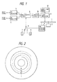
- the disk 1 is made to function as a master disk (recorded original disk) throughout developing treatment. Any disk obtained from this master disk, as shown in Fig. 2, also include the carrier signals f1 (the solid line) and f2 (the dashed line), recorded on adjacent tracks, within the information signal.
- FIG. 3 a block diagram of Fig. 3, an embodiment of the tracking error detector circuit according to the present invention for use in an apparatus for playing prerecorded disk will be described hereafter.
- the beams include a main laser S M for reading prerecorded information, and two detector sub-beams SA and SB for monitoring the actual position of main beam SM relative its desired position.
- Sub-beams SA and SB are arranged to precede and succeed the main beam SM as it moves perpendicular to the direction of rotation of the disk (i.e. radially).
- all three beams are aligned in a relationship such that a line connecting the optical axes of the beams SM, SA and SB has a predetermined offset angle relative to the tangential direction of rotation of the tracks as shown in Fig. 3.
- the beams S A , S B and S M reflected off the disk surface are incident respectively into photoelectric conversion elements 21, 22 and 23 provided within the pickup.
- An output of the photoelectric conversion element 21, generated by sub-beam S A is supplied to a pair of BPFs (band pass filters) 24 and 25.
- the BPFs 24 and 25 have passing bands corresponding to the frequencies of the carrier signals f1 and f2, respectively.
- the components of the carrier signals f1 and f2 passed through the BPFs 24 and 25, respectively, are amplitude-detected by amplitude detection circuits 26 and 27.
- an output of the photoelectric conversion element 22, generated by sub-beam S B is supplied to a pair of BPFs 28 and 29 having passing bands corresponding to the respective frequencies of the carrier signals f1 and f2.
- the components of the carrier signals f1 and f2 passed through the BPFs 28 and 29, respectively, are amplitude-detected by amplitude detection circuits 30 and 31.
- a difference between the outputs of the amplitude detection circuits 26 and 30, is derived as a first error signal f1TE by means of a differential amplifier 32, while a difference between the outputs of the amplitude detector circuits 27 and 31, is derived as a second error signal F2TE by means of a differential amplifier 33.
- the first and second error signals are supplied to a selection switch 34, in which one of the two error signals is selected and outputted as a tracking error signal TE.
- an output of the photoelectric element 23, generated by the main beam S M is supplied as an RF signal to a demodulating system and simultaneously supplied to a pair of BPFs 35 and 36 having passing bands corresponding to the respective frequencies of the carrier signals f1 and f2.
- the components of the signals f1 and f2 passed through the BPFs 35 and 35, respectively, are amplitude-detected by amplitude detection circuits 37 and 38.
- a difference between signal amplitudes is generated by a differential amplifier 39 and supplied to a comparator 40, which compares amplifier 39's output to a zero level reference input.
- the output of the comparator 40 is supplied, as a switch control signal, to the selection switch 34, wherein this output's polarity indicates which prerecorded track the main beam S M is positioned above.
- the carrier signal multiplexed within the prerecorded audio and video information signal alternates between f1 and f2 each revolution of the disk. This carrier signal alternation causes the output of comparator 40 to change polarity, thus indicating the disk has completed a revolution.
- the present invention is not limited to this embodiment.
- a synchronizing signal is previously recorded every rotation of a disk so that the synchronizing signal is detected from the output of the main beam S M .
- Figure 4 (a) illustrates when the main beam S M crosses recording tracks at a constant speed in the radial direction of the disk. Consequently, an RF signal is output from the photoelectric conversion element 23 based on the signal picked up by main beam S M .
- the amplitudes of the respective components of the carrier signals f1 and f2 (which are the outputs of the amplitude detection circuits 37 and 38) change as shown in Fig. 4(B), and the first and second error signals f1TE and f2TE (which are the outputs of the differential amplifiers 32 and 33) vary as shown in Fig. 4(C).
- a difference signal as shown in Fig.
- Tracking servo is based on the tracking error signal TE, such that the position of the main beam S M , along the disk radius, is controlled to zero the amplitude of difference signals f1TE and f2TE. By adjusting the tracking servo to maintain zero amplitude signals f1TE and f2TE, the main beam S M is centered on the desired track.
- the tracking error detection circuit of the instant invention can be used with an ordinary disk provided the tracking error detection circuit of the present invention is arranged to be changeable with the conventional tracking error detection circuits.
- Fig. 5 is a block diagram showing another embodiment of the tracking error detection circuit according to the present invention. It is assumed that in a disk to which the present invention is applied, a carrier signal having a predetermined frequency (for example, a frequency f1) has been recorded every other rotation of the disk, via multiplexing with the informaion signal.
- the respective outputs of the photoelectric conversion elements 21 and 22, based on tracking sub-beams S A and S B are passed through BPFs 41 and 42, wherein each filter has a passing band corresponding to the frequency f1.
- the filter outputs are then amplitude-detected by circuits 43 and 44, respectively.
- a difference in output between the amplitude detection circuits 43 and 44 is derived by a differential amplifier 46 as an error signal f1TE.
- an output of the photoelectric conversion element 23, generated from main beam S M is passed through a BPF 46 having a passing band corresponding to the frequency f1, amplitude-detected by an amplitude detection circuit 47, and then supplied to a comparator 48.
- Comparator 48 compares this output to a predetermined reference voltage level V ref .
- a comparison output of the comparator 48 is supplied, as a switch control signal, to a polarity switching circuit 49 which is supplied also with the error signal F1TE.
- the polarity of the output of the comparator 48 indicates whether or not the main beam S M is positioned on the recording track, which contains carrier signal F1. Thereby, each rotation of the disk can be detected through the polarity change.
- the present invention is not limited to this embodiment. similarly to the first embodiment described above, it is possible that a synchronizing signal is previously recorded in every rotation of the disk, so that the synchronizing signal is detected from the output of main beam S M .
- photoelectric conversion element 23 When the main beam spot S M crosses recording tracks while moving at a constant speed in the radial direction of a disk, photoelectric conversion element 23 outputs an RF signal, generated by main beam SM, which changes as shown in Fig. 6(A).
- the output detection circuit 47 which represents the carrier signal f1 component of the main beam SM, changes as shown in Fig. 6(B), and the error signal f1TE, which represents the output of the differential amplifier 45 changes as shown in Fig. 6(C).
- the output of detection circuit 47 is compared with the reference level V ref in the comparator 48 and this comparator output is then feed to polarity switching circuit 49.
- This comparator controls polarity switching circuit 49, which alternates the polarity of error signal f1TE. Accordingly, a tracking error signal TE as shown in Fig. 6(E) is obtained from the output of switching circuit 49.
- Tracking servo is based on the tracking error signal TE, such that it is possible to generate the tracking error signal TE to control the main beam even if a track pitch is narrow.
- the tracking error detector circuit according to the present invention is arranged such that the tracking error signal is generated from the carrier signal components detected by the sub-beams. Accordingly, it is possible to generate the tracking error signal which can correctly perform tracking servo operations even when the track pitch is small.
Landscapes
- Optical Recording Or Reproduction (AREA)
- Moving Of The Head To Find And Align With The Track (AREA)
Abstract
A tracking error detector circuit to maintain correct disk tracking on high density disks is provided within an apparatus for playing a prerecorded disk (1). The disk (1) contains two carrier signals with frequencies f₁ and f₂, which are alternately superimposed onto an information signal each rotation of the disk (1). The tracking error detection circuit includes circuitry (24-33) to determine, as a first error signal (f₁TE), the difference in amplitude between the f₁ frequency components of the tracking sub-beams (SA,SB) and, as a second error signal (f₂TE), the difference in amplitude between f₂ frequency components of the tracking sub-beams (SA,SB). The detection circuit further includes means (35-40) to detect one rotation of the disk (1) and means (34) for alternately selecting the first and second error signals each time the rotation sensor detects a disk revolution. This selected error signal acts as the tracking error signal (TE) for the succeeding revolution of the disk.
Description
- The present invention relates to the use of information-recorded disk tracking carrier signals, and a playing apparatus therefor. More specifically, it relates to a tracking error detection circuit in an information-recorded disk playing apparatus.
- Optical disk players used to play video disk, digital audio disk, etc., often experience difficulty following prerecorded tracks of information upon the disk, primarily when these tracks deviate from their standard path. To correct this tracking problem, disc players include a tracking servo apparatus, which includes a three-beam tracking system. More specifically, the three beam system includes a main central beam for reading prerecorded information and two tracking detector sub-beams arranged to precede and succeed the main beam, respectively, as the main beam moves perpendicular to the direction of disc rotation. Tracking sub-beams generate outputs A and B, which includes any disk information picked up by the sub-beams and represents their positions relative to the track intended to be read by the main beam. These three beams also lie along a line connecting the optical axes of each beam whereby the connecting line has a predetermined offset angle relative to a line tangential to the direction of disk rotation. A tracking error signal TE is generated from a difference (A - B) between the low frequency components of outputs A and B generated by the tracking sub-beams. This error signal is then used to correctly position the main beam over a desired track.
- Recently, however, technological advances allow denser information storage on each disk, which causes the pitch of recording tracks to becomes narrower. Hence, the conventional tracking error detector circuit is unable to distinguish between light and dark (i.e., the change in the amplitude of an RF signal) when the sub-beams cross tracks. Consequently, an adequate tracking error signal cannot be generated and tracking servo integrity cannot be maintained. Figures 7(a)-7(c) show waveforms read from a disk in which the track pitch is large and figures 8(a)-8(c) show waveforms from a disk in which the track pitch is small. Figures 7(a) and 8(a) show the main RF signal as the servo apparatus is moved radially across the disk. Fig. 7(b) and 8(b) show outputs A and B from tracking sub-beams moved in a similar radial motion, and fig. 7(c) and 8(c) show respective error signals TE. It is apparent from fig. 8(c) that small track pitch creates an error signal TE amplitude too small to correctly control the tracking servo apparatus.
- It is therefore an object of the present invention to provide a tracking error detection circuit which generates a tracking error signal amplitude large enough to control the tracking servo, especially when track pitch is small.
- In the present invention, a tracking error detector circuit is provided in an apparatus for playing an prerecorded disk. The disk contains two carrier signals with frequencies f₁ and f₂, which are alternately superimposed onto an information signal each rotation of the prerecorded disk. This system uses frequency multiplexing to record the carrier signals and information signal onto the disk. The tracking error detection circuit includes circuitry to determine, as a first error signal, the difference in amplitude between the f1 frequency components of the tracking sub-beams, and as a second error signal, the difference in amplitude between f₂ frequency components of the tracking sub-beams. The detection circuit further includes a sensor to detect one rotation of the prerecorded disk and a selection circuit, which alternately selects the first and second error signals each time the rotation sensor detects a disk revolution. This selected error signal acts as the tracking error signal for the succeeding revolution of the disk.
- In another embodiment, the present invention constitutes a tracking error detector circuit provided in an apparatus for playing an prerecorded disk, which includes one carrier signal having frequency f1 superimposed onto every other track of the information signal of the prerecorded disk by frequency multiplexing. Frequency multiplexing allows the carrier signal to be recorded with every other track of information on the disk. The tracking error detection circuit determines, as an error signal, the difference in amplitude between the carrier signal f1 components picked up by the tracking sub-beams. This difference is feed into a polarity switching circuit, which outputs the error tracking signal f1TE. In addition, the detection circuit includes a comparitor, which compares a reference voltage to the carrier signal component f1 of the main beam signal, provided the track picked up by the main beam includes a carrier signal. The comparator output functions as a switching control for the polarity switching circuit, thereby switching the polarity of the tracking error signal every disk revolution.
- In the drawings:-
- Fig. 1 is a block diagram showing an example of a recording system for a disk to which the present invention is applied;
- Fig. 2 is a view showing the relation between carrier signals f₁ and f₂ on recording tracks of a disk recorded by the recording system of figure 1;
- Fig. 3 is a block diagram showing an embodiment of the tracking error detection circuit according to the present invention;
- Fig. 4 is a view showing signal waveforms with respect to recording tracks, for explaining the operation of the circuit shown in Fig. 3;
- Fig. 5 is a block diagram showing another embodiment of the tracking error detection circuit according to the present invention;
- Fig. 6 is a view showing signal waveforms with respect to recording tracks, for explaining the operation of the circuit shown in Fig. 5;
- Fig. 7 is a view showing waveforms of an RF signal (a) in the case where a track pitch is large, outputs A and B (b) detected on the basis of a pair of sub-beam stops respectively, and (c) a tracking error signal TE; and
- Fig. 8 is a view showing waveforms of an RF signal (a) in the case where the tracking pitch is small, outputs A and B (b) detected on the basis of a pair of the sub-beam spots respectively, and (c) a tracking error signal TE.
- Referring to the drawings, embodiments of the present invention will be described hereunder.
- Fig. 1 is a block diagram showing an example of a record system to which the present invention is applied. In Fig. 1, the
master disk 1 is rotated by an electric motor and information signals, such as audio and video signals are recorded thereon. While themaster disk 1 rotates, a rotation detector 3 senses when the disk completes each revolution. The rotation detector 3 is made of a well-known sensor combination such as a reflecting mirror and a photo-reflector. - The two-channel audio and video signals are modulated by FM modulators 4 and 5 into an audio FM modulated wave and a video FM modulated wave, respectively. Both the modulated waves are subjected to frequency multiplexing by
circuit 6. During which,oscillators selection switch 9. The selection switch 9 alternately selects carrier signals f₁ and f₂ every time the rotation detector 3 senses the disk has completed a revolution. The selected carrier signal f₁ or f₂ is supplied to themultiplexing circuit 6 and the subjected to frequency-multiplexing with the audio and video information signal. The multiplexed signal is limited in amplitude by alimiter circuit 10 and then supplied to alight modulator 11, which turns a laser beam emitted from alaser light source 12 on and off. The laser beam illuminates a photo-resist surface of themaster disk 1 so that pits (exposed portions) representing recorded information are burnt into the photo-resist surface. Thedisk 1 is made to function as a master disk (recorded original disk) throughout developing treatment. Any disk obtained from this master disk, as shown in Fig. 2, also include the carrier signals f1 (the solid line) and f2 (the dashed line), recorded on adjacent tracks, within the information signal. - Referring to a block diagram of Fig. 3, an embodiment of the tracking error detector circuit according to the present invention for use in an apparatus for playing prerecorded disk will be described hereafter. In Fig. 3, three laser beams are radiated onto the disk's prerecorded tracks to read each track. The beams include a main laser SM for reading prerecorded information, and two detector sub-beams SA and SB for monitoring the actual position of main beam SM relative its desired position. Sub-beams SA and SB are arranged to precede and succeed the main beam SM as it moves perpendicular to the direction of rotation of the disk (i.e. radially). In addition, all three beams are aligned in a relationship such that a line connecting the optical axes of the beams SM, SA and SB has a predetermined offset angle relative to the tangential direction of rotation of the tracks as shown in Fig. 3. The beams SA, SB and SM reflected off the disk surface are incident respectively into
photoelectric conversion elements - An output of the
photoelectric conversion element 21, generated by sub-beam SA, is supplied to a pair of BPFs (band pass filters) 24 and 25. TheBPFs 24 and 25 have passing bands corresponding to the frequencies of the carrier signals f₁ and f₂, respectively. The components of the carrier signals f₁ and f₂ passed through theBPFs 24 and 25, respectively, are amplitude-detected byamplitude detection circuits photoelectric conversion element 22, generated by sub-beam SB, is supplied to a pair ofBPFs BPFs amplitude detection circuits amplitude detection circuits differential amplifier 32, while a difference between the outputs of theamplitude detector circuits differential amplifier 33. The first and second error signals are supplied to aselection switch 34, in which one of the two error signals is selected and outputted as a tracking error signal TE. - On the other hand, an output of the
photoelectric element 23, generated by the main beam SM, is supplied as an RF signal to a demodulating system and simultaneously supplied to a pair of BPFs 35 and 36 having passing bands corresponding to the respective frequencies of the carrier signals f₁ and f₂. The components of the signals f₁ and f₂ passed through the BPFs 35 and 35, respectively, are amplitude-detected byamplitude detection circuits differential amplifier 39 and supplied to acomparator 40, which comparesamplifier 39's output to a zero level reference input. The output of thecomparator 40 is supplied, as a switch control signal, to theselection switch 34, wherein this output's polarity indicates which prerecorded track the main beam SM is positioned above. In referencing above, it is noted that the carrier signal multiplexed within the prerecorded audio and video information signal alternates between f₁ and f₂ each revolution of the disk. This carrier signal alternation causes the output ofcomparator 40 to change polarity, thus indicating the disk has completed a revolution. - Although the above description has set forth that one rotation of the disk is detected by comparing the respective amplitudes of the components of the signals f₁ and f₂, the present invention is not limited to this embodiment. For example, it is possible that a synchronizing signal is previously recorded every rotation of a disk so that the synchronizing signal is detected from the output of the main beam SM.
- Referring to a waveform diagram of Fig. 4, the operation of the circuit arrangement of figure 3 will be described hereunder.
- Figure 4 (a) illustrates when the main beam SM crosses recording tracks at a constant speed in the radial direction of the disk. Consequently, an RF signal is output from the
photoelectric conversion element 23 based on the signal picked up by main beam SM. The amplitudes of the respective components of the carrier signals f₁ and f₂ (which are the outputs of theamplitude detection circuits 37 and 38) change as shown in Fig. 4(B), and the first and second error signals f₁TE and f₂TE (which are the outputs of thedifferential amplifiers 32 and 33) vary as shown in Fig. 4(C). As a result, a difference signal, as shown in Fig. 4(D) is obtained as the output of thedifferential amplifier 39, so that the first error signal f1TE is selected, as output TE, in the period in which difference signal (f1-f2) is positive and second error signal f₂TE is selected, as output TE, in the period in which difference signal (f1-f2) is negative. Accordingly, the tracking error signal TE as shown in Fig. 4(E) is obtained. - Tracking servo is based on the tracking error signal TE, such that the position of the main beam SM, along the disk radius, is controlled to zero the amplitude of difference signals f1TE and f2TE. By adjusting the tracking servo to maintain zero amplitude signals f1TE and f2TE, the main beam SM is centered on the desired track.
- Accordingly, as track pitch narrows, the respective outputs of the BPFs are not affected by the adjacent tracks and it is possible to generate the tracking error signal TE. Also, interference from noise in other frequency bands is negligible, since the BPF outputs are used. Furthermore, since the present optical system has the same structure as a conventional optical system, the tracking error detection circuit of the instant invention can be used with an ordinary disk provided the tracking error detection circuit of the present invention is arranged to be changeable with the conventional tracking error detection circuits.
- Fig. 5 is a block diagram showing another embodiment of the tracking error detection circuit according to the present invention. It is assumed that in a disk to which the present invention is applied, a carrier signal having a predetermined frequency (for example, a frequency f₁) has been recorded every other rotation of the disk, via multiplexing with the informaion signal. In the figure 5, the respective outputs of the
photoelectric conversion elements BPFs circuits amplitude detection circuits differential amplifier 46 as an error signal f₁TE. - On the other hand, an output of the
photoelectric conversion element 23, generated from main beam SM, is passed through aBPF 46 having a passing band corresponding to the frequency f₁, amplitude-detected by anamplitude detection circuit 47, and then supplied to acomparator 48.Comparator 48 compares this output to a predetermined reference voltage level Vref. Next, a comparison output of thecomparator 48 is supplied, as a switch control signal, to apolarity switching circuit 49 which is supplied also with the error signal F₁TE. The polarity of the output of thecomparator 48 indicates whether or not the main beam SM is positioned on the recording track, which contains carrier signal F₁. Thereby, each rotation of the disk can be detected through the polarity change. - Although the above embodiment sets forth that one rotation of the disk is detected through a comparison between the reference voltage level, Vref and the amplitude of the carrier signal f₁ component read by main beam SM, the present invention is not limited to this embodiment. similarly to the first embodiment described above, it is possible that a synchronizing signal is previously recorded in every rotation of the disk, so that the synchronizing signal is detected from the output of main beam SM.
- Referring to a waveform diagram of Fig. 6, the circuit operation of figure 5 will be described hereunder.
- When the main beam spot SM crosses recording tracks while moving at a constant speed in the radial direction of a disk,
photoelectric conversion element 23 outputs an RF signal, generated by main beam SM, which changes as shown in Fig. 6(A). Theoutput detection circuit 47, which represents the carrier signal f₁ component of the main beam SM, changes as shown in Fig. 6(B), and the error signal f₁TE, which represents the output of thedifferential amplifier 45 changes as shown in Fig. 6(C). During operation, the output ofdetection circuit 47 is compared with the reference level Vref in thecomparator 48 and this comparator output is then feed topolarity switching circuit 49. This comparator controlspolarity switching circuit 49, which alternates the polarity of error signal f1TE. Accordingly, a tracking error signal TE as shown in Fig. 6(E) is obtained from the output of switchingcircuit 49. - Tracking servo is based on the tracking error signal TE, such that it is possible to generate the tracking error signal TE to control the main beam even if a track pitch is narrow.
- As described above, the tracking error detector circuit according to the present invention is arranged such that the tracking error signal is generated from the carrier signal components detected by the sub-beams. Accordingly, it is possible to generate the tracking error signal which can correctly perform tracking servo operations even when the track pitch is small.
Claims (8)
- An information-recorded disk (1) of the type including a tracking signal superimposed on an information signal of the disk, the disk comprising a spiral track on which the information signal is recorded, with a carrier signal (f₁) constituting the tracking signal recorded on alternate turns of the track.
- A tracking error detection circuit for an apparatus for playing an information recorded disk (1) in which a carrier signal having a predetermined frequency (f₁) is superimposed, every other rotation, on an information signal and recorded together with the information signal on the disk (1), the circuit comprising:
means for producing a main beam (SM),
means for producing a pair of tracking sub-beams (SA,SB) which generate a pair of tracking outputs and are positioned to precede and succeed the main beam (SM) as the main beam (SM) moves in a radial direction relative to rotation of the disk (1), wherein each of the pair of tracking outputs may include a carrier signal component;
means (41-45) for deriving, as an error signal, a difference in amplitude between the carrier signal components included in the pair of tracking outputs,
detector means (46,47,48) for detecting one rotation of the information-recorded disk (1); and,
means (49) for switching the polarity of the error signal whenever the detection means output is generated, whereby the alternately switched error signal polarity acts as a tracking error signal (TE). - A circuit according to claim 2, wherein the detector means includes a comparator means (48) for comparing a predetermined reference level (Vref) with an amplitude of the carrier signal component included in the main beam (SM) output.
- A circuit according to claim 2, further comprising a synchronising signal recorded on the information-recorded disk (1) every rotation of the disk, and wherein the detector means includes a synchronisation detector means for detecting the synchronising signal from the main beam (SM) output.
- An information-recorded disk (1) of the type comprising a spiral track on which is recorded a tracking signal superimposed on an information signal of the disk, the disk comprising:
two carrier signals having different frequencies (f₁, f₂), wherein the carrier signals constitute the tracking signal, and
an information signal having a frequency band which does not include the frequencies (f₁,f₂) used by the two carrier signals,
the carrier signals (f₁,f₂) being alternately multiplexed with the information signal on each turn of the track, and the multiplexed carrier signal and information signal being recorded onto the disk. - A tracking error detection circuit for an apparatus for playing an information recorded disk (1) in which carrier signals having frequencies f₁ and f₂ are alternately multiplexed on each rotation of the disk with an information signal and recorded together onto the disk, the circuit comprising:
means for producing a main beam (SM),
means for producing a pair of tracking sub-beams (SA,SB) which generate a pair of tracking outputs and are positioned to precede and succeed the main beam (SM) as the main beam moves in a radial direction relative to rotation of the disk (1), wherein each of the pair of tracking outputs may include f₁ and f₂ components representing the carrier signals;
means (24,26,28,30,32) for deriving, as a first error signal (f₁TE), a difference in amplitude between f₁ components of each tracking output,
means (25,27,29,31,33) for deriving, as a second error signal (f₂TE), a difference in amplitude between f₂ components of each tracking output,
detector means (35-40) for detecting one rotation of the information-recorded disk (1); and,
means (34) for alternately selecting the first and second error signals whenever a detection output of the detector means (35-40) is generated, thereby outputting the selected one of the first and second error signals as a tracking error signal (TE). - A circuit according to claim 6, wherein the detector means (35-40) includes comparator means (40) for comparing amplitudes between an f₁ component and f₂ component of an output of the main beam (SM).
- A circuit according to claim 6, wherein:
a synchronising signal is recorded on the information-recorded disk (1) every rotation of the disk, and the detector means includes a synchronisation detector means for detecting the synchronising signal from an output of the main beam (SM).
Applications Claiming Priority (2)
| Application Number | Priority Date | Filing Date | Title |
|---|---|---|---|
| JP331586/89 | 1989-12-21 | ||
| JP1331586A JPH03192583A (en) | 1989-12-21 | 1989-12-21 | Information recording disk storing pilot signal for tracking and its player |
Publications (2)
| Publication Number | Publication Date |
|---|---|
| EP0435422A2 true EP0435422A2 (en) | 1991-07-03 |
| EP0435422A3 EP0435422A3 (en) | 1992-02-19 |
Family
ID=18245307
Family Applications (1)
| Application Number | Title | Priority Date | Filing Date |
|---|---|---|---|
| EP19900309031 Withdrawn EP0435422A3 (en) | 1989-12-21 | 1990-08-17 | Information-recorded disk carrying tracking pilot signal and playing apparatus therefor |
Country Status (3)
| Country | Link |
|---|---|
| US (1) | US5121375A (en) |
| EP (1) | EP0435422A3 (en) |
| JP (1) | JPH03192583A (en) |
Families Citing this family (12)
| Publication number | Priority date | Publication date | Assignee | Title |
|---|---|---|---|---|
| US5253241A (en) * | 1990-08-30 | 1993-10-12 | Nec Corporation | Optical recording apparatus for recording auxillary signals used for focus control |
| JPH04335214A (en) * | 1991-05-09 | 1992-11-24 | Olympus Optical Co Ltd | Information recording and reproducing device |
| US5633854A (en) * | 1992-02-19 | 1997-05-27 | Sony Corporation | Methods and apparatus for reproducing data recorded on an optical recording medium |
| EP0580876B1 (en) * | 1992-02-19 | 1999-05-12 | Sony Corporation | Optical recording medium, its recording method, its reproducing method, and method for generating tracking error signal |
| JPH08249677A (en) * | 1995-03-09 | 1996-09-27 | Nec Corp | Method and apparatus for track-jump optical disk |
| JPH08321045A (en) * | 1995-05-23 | 1996-12-03 | Sharp Corp | Optical disk device |
| US6025970A (en) * | 1997-08-07 | 2000-02-15 | International Business Machines Corporation | Digital demodulation of a complementary two-frequency servo PES pattern |
| US5966264A (en) * | 1997-08-07 | 1999-10-12 | International Business Machines Cororation | Two frequency servo PES pattern |
| CN1258757C (en) * | 2000-06-22 | 2006-06-07 | Tdk株式会社 | Optical recording medium and optical recording method |
| EP1297528A1 (en) * | 2000-06-23 | 2003-04-02 | Koninklijke Philips Electronics N.V. | Device for recording and/or reproducing an optical record carrier |
| JP4327693B2 (en) * | 2004-09-30 | 2009-09-09 | 株式会社東芝 | Optical disc apparatus and optical detection signal processing method |
| US20090035249A1 (en) * | 2007-08-02 | 2009-02-05 | Bhatia Sujata K | Method of inhibiting proliferation of Escherichia coli |
Citations (4)
| Publication number | Priority date | Publication date | Assignee | Title |
|---|---|---|---|---|
| JPS5744238A (en) * | 1981-07-13 | 1982-03-12 | Hitachi Ltd | Information recorder |
| JPS5826369A (en) * | 1981-08-07 | 1983-02-16 | Akai Electric Co Ltd | Video signal recording and reproducing system |
| US4404599A (en) * | 1976-04-08 | 1983-09-13 | Victor Company Of Japan, Ltd. | Laser recording information and pilot signals for tracking on a grooveless recording |
| US4750162A (en) * | 1985-07-16 | 1988-06-07 | Victor Company Of Japan, Ltd. | Optical tracking system utilizing three photo-detectors |
Family Cites Families (4)
| Publication number | Priority date | Publication date | Assignee | Title |
|---|---|---|---|---|
| JPS57105828A (en) * | 1980-12-19 | 1982-07-01 | Matsushita Electric Ind Co Ltd | Optical disk recording and reproducing system |
| JPS60119641A (en) * | 1983-12-01 | 1985-06-27 | Pioneer Electronic Corp | Tracking error signal generating device |
| JPS60234232A (en) * | 1984-05-07 | 1985-11-20 | Matsushita Electric Ind Co Ltd | Optical disk and its tracking method |
| JPS62165736A (en) * | 1986-01-16 | 1987-07-22 | Matsushita Electric Ind Co Ltd | Optical disk reproducing device |
-
1989
- 1989-12-21 JP JP1331586A patent/JPH03192583A/en active Pending
-
1990
- 1990-08-15 US US07/567,506 patent/US5121375A/en not_active Expired - Fee Related
- 1990-08-17 EP EP19900309031 patent/EP0435422A3/en not_active Withdrawn
Patent Citations (4)
| Publication number | Priority date | Publication date | Assignee | Title |
|---|---|---|---|---|
| US4404599A (en) * | 1976-04-08 | 1983-09-13 | Victor Company Of Japan, Ltd. | Laser recording information and pilot signals for tracking on a grooveless recording |
| JPS5744238A (en) * | 1981-07-13 | 1982-03-12 | Hitachi Ltd | Information recorder |
| JPS5826369A (en) * | 1981-08-07 | 1983-02-16 | Akai Electric Co Ltd | Video signal recording and reproducing system |
| US4750162A (en) * | 1985-07-16 | 1988-06-07 | Victor Company Of Japan, Ltd. | Optical tracking system utilizing three photo-detectors |
Non-Patent Citations (2)
| Title |
|---|
| PATENT ABSTRACTS OF JAPAN vol. 6, no. 116 (P-125)(994) 29 June 1982 & JP-A-57 044 238 ( HITACHI SEISAKUSHO K.K. ) 12 March 1982 * |
| PATENT ABSTRACTS OF JAPAN vol. 7, no. 105 (P-195)(1250) 7 May 1983 & JP-A-58 026 369 ( AKAI DENKI K.K. ) 16 February 1983 * |
Also Published As
| Publication number | Publication date |
|---|---|
| US5121375A (en) | 1992-06-09 |
| EP0435422A3 (en) | 1992-02-19 |
| JPH03192583A (en) | 1991-08-22 |
Similar Documents
| Publication | Publication Date | Title |
|---|---|---|
| US4338682A (en) | Tracking servo system of video disc player | |
| CA1145038A (en) | Optical scanning apparatus with focussing system | |
| EP0093582B1 (en) | Scanning servo system for optical-disc information reproducing apparatus | |
| EP0305049B1 (en) | Apparatus for detecting whether information is recorded on a storage device | |
| US6137758A (en) | Optical disc discriminating apparatus | |
| EP0272873B1 (en) | Tracking servo systems for optical disc players | |
| US5121375A (en) | Information-recorded disk carrying tracking pilot signal and playing apparatus therefor | |
| US4803677A (en) | Rotary recording medium having a guide track and recording and reproducing apparatus therefor | |
| US4084185A (en) | Record carrier on which information is stored in an optically readable structure | |
| US4736354A (en) | Focus servo device for detecting and compensating for disk abnormalities | |
| EP0390977B1 (en) | Servo system for a disc player | |
| EP0745976A2 (en) | Method and apparatus for tracking correction and optical disk for use therein | |
| JPH0227734B2 (en) | ||
| EP0087973B1 (en) | Tracking servo system for optical-disc information reproducing apparatus | |
| US6590844B2 (en) | Disc-shaped recording medium, disc recording and/or reproducing method and apparatus and tilt detection method | |
| JPS5931129B2 (en) | optical reproduction device | |
| JPH0778428A (en) | Access direction detecting circuit for disk device | |
| JP2764960B2 (en) | Recording / playback method | |
| JPS6120929B2 (en) | ||
| JPS6143770B2 (en) | ||
| US5260930A (en) | Optical information recording medium and reproducing apparatus for reproducing information from the medium | |
| EP0471917A2 (en) | Tracking servo system | |
| US4845572A (en) | Multiplied-speed reproducing system in information reproducing apparatus | |
| JPS5835766A (en) | Digital audio disc player | |
| JPS6045483B2 (en) | Tracking servo device in information reading device |
Legal Events
| Date | Code | Title | Description |
|---|---|---|---|
| PUAI | Public reference made under article 153(3) epc to a published international application that has entered the european phase |
Free format text: ORIGINAL CODE: 0009012 |
|
| AK | Designated contracting states |
Kind code of ref document: A2 Designated state(s): DE FR GB |
|
| PUAL | Search report despatched |
Free format text: ORIGINAL CODE: 0009013 |
|
| AK | Designated contracting states |
Kind code of ref document: A3 Designated state(s): DE FR GB |
|
| 17P | Request for examination filed |
Effective date: 19920731 |
|
| STAA | Information on the status of an ep patent application or granted ep patent |
Free format text: STATUS: THE APPLICATION HAS BEEN WITHDRAWN |
|
| 18W | Application withdrawn |
Withdrawal date: 19940614 |