EP0435216A2 - Apparatus for and method of recording image - Google Patents
Apparatus for and method of recording image Download PDFInfo
- Publication number
- EP0435216A2 EP0435216A2 EP19900125231 EP90125231A EP0435216A2 EP 0435216 A2 EP0435216 A2 EP 0435216A2 EP 19900125231 EP19900125231 EP 19900125231 EP 90125231 A EP90125231 A EP 90125231A EP 0435216 A2 EP0435216 A2 EP 0435216A2
- Authority
- EP
- European Patent Office
- Prior art keywords
- photosensitive material
- main roller
- film
- roller
- feeding
- Prior art date
- Legal status (The legal status is an assumption and is not a legal conclusion. Google has not performed a legal analysis and makes no representation as to the accuracy of the status listed.)
- Withdrawn
Links
Images


Classifications
-
- H—ELECTRICITY
- H04—ELECTRIC COMMUNICATION TECHNIQUE
- H04N—PICTORIAL COMMUNICATION, e.g. TELEVISION
- H04N1/00—Scanning, transmission or reproduction of documents or the like, e.g. facsimile transmission; Details thereof
- H04N1/00567—Handling of original or reproduction media, e.g. cutting, separating, stacking
- H04N1/0057—Conveying sheets before or after scanning
- H04N1/00588—Conveying sheets before or after scanning to the scanning position
-
- G—PHYSICS
- G03—PHOTOGRAPHY; CINEMATOGRAPHY; ANALOGOUS TECHNIQUES USING WAVES OTHER THAN OPTICAL WAVES; ELECTROGRAPHY; HOLOGRAPHY
- G03B—APPARATUS OR ARRANGEMENTS FOR TAKING PHOTOGRAPHS OR FOR PROJECTING OR VIEWING THEM; APPARATUS OR ARRANGEMENTS EMPLOYING ANALOGOUS TECHNIQUES USING WAVES OTHER THAN OPTICAL WAVES; ACCESSORIES THEREFOR
- G03B27/00—Photographic printing apparatus
- G03B27/32—Projection printing apparatus, e.g. enlarger, copying camera
- G03B27/52—Details
- G03B27/58—Baseboards, masking frames, or other holders for the sensitive material
- G03B27/587—Handling photosensitive webs
- G03B27/588—Supply rolls; Cutting arrangements
-
- H—ELECTRICITY
- H04—ELECTRIC COMMUNICATION TECHNIQUE
- H04N—PICTORIAL COMMUNICATION, e.g. TELEVISION
- H04N1/00—Scanning, transmission or reproduction of documents or the like, e.g. facsimile transmission; Details thereof
- H04N1/00567—Handling of original or reproduction media, e.g. cutting, separating, stacking
- H04N1/0057—Conveying sheets before or after scanning
- H04N1/00591—Conveying sheets before or after scanning from the scanning position
-
- H—ELECTRICITY
- H04—ELECTRIC COMMUNICATION TECHNIQUE
- H04N—PICTORIAL COMMUNICATION, e.g. TELEVISION
- H04N1/00—Scanning, transmission or reproduction of documents or the like, e.g. facsimile transmission; Details thereof
- H04N1/00567—Handling of original or reproduction media, e.g. cutting, separating, stacking
- H04N1/0057—Conveying sheets before or after scanning
- H04N1/00599—Using specific components
- H04N1/00602—Feed rollers
-
- H—ELECTRICITY
- H04—ELECTRIC COMMUNICATION TECHNIQUE
- H04N—PICTORIAL COMMUNICATION, e.g. TELEVISION
- H04N1/00—Scanning, transmission or reproduction of documents or the like, e.g. facsimile transmission; Details thereof
- H04N1/00567—Handling of original or reproduction media, e.g. cutting, separating, stacking
- H04N1/00665—Details specific to handling of web-shaped media, e.g. paper or film rolls
- H04N1/00673—Controlling the amount of slack or tension control
-
- H—ELECTRICITY
- H04—ELECTRIC COMMUNICATION TECHNIQUE
- H04N—PICTORIAL COMMUNICATION, e.g. TELEVISION
- H04N1/00—Scanning, transmission or reproduction of documents or the like, e.g. facsimile transmission; Details thereof
- H04N1/00567—Handling of original or reproduction media, e.g. cutting, separating, stacking
- H04N1/00665—Details specific to handling of web-shaped media, e.g. paper or film rolls
- H04N1/00676—Cutting
-
- Y—GENERAL TAGGING OF NEW TECHNOLOGICAL DEVELOPMENTS; GENERAL TAGGING OF CROSS-SECTIONAL TECHNOLOGIES SPANNING OVER SEVERAL SECTIONS OF THE IPC; TECHNICAL SUBJECTS COVERED BY FORMER USPC CROSS-REFERENCE ART COLLECTIONS [XRACs] AND DIGESTS
- Y10—TECHNICAL SUBJECTS COVERED BY FORMER USPC
- Y10T—TECHNICAL SUBJECTS COVERED BY FORMER US CLASSIFICATION
- Y10T83/00—Cutting
- Y10T83/444—Tool engages work during dwell of intermittent workfeed
- Y10T83/4455—Operation initiated by work-driven detector means to measure work length
-
- Y—GENERAL TAGGING OF NEW TECHNOLOGICAL DEVELOPMENTS; GENERAL TAGGING OF CROSS-SECTIONAL TECHNOLOGIES SPANNING OVER SEVERAL SECTIONS OF THE IPC; TECHNICAL SUBJECTS COVERED BY FORMER USPC CROSS-REFERENCE ART COLLECTIONS [XRACs] AND DIGESTS
- Y10—TECHNICAL SUBJECTS COVERED BY FORMER USPC
- Y10T—TECHNICAL SUBJECTS COVERED BY FORMER US CLASSIFICATION
- Y10T83/00—Cutting
- Y10T83/444—Tool engages work during dwell of intermittent workfeed
- Y10T83/4458—Work-sensing means to control work-moving or work-stopping means
Definitions
- This invention relates to an image recorder, such as a flat-bed type color scanner, for recording an image to be reproduced onto a photosensitive material sheet.
- a photosensitive material is drawn out of a roll of photosensitive material, and then is fed in the feed scanning direction while being scanned by a laser beam in the primary scanning direction, which is approximately perpendicular to the feed scanning direction, whereby the image is recorded onto the photosensitive material.
- a long photosensitive film (hereinafter referred as a "film”) is stored in the form of a roll and is accommodated within a film case.
- a film drawn out of the film case is held between a main roller and nip rollers.
- the film is fed in the feed scanning direction as the main roller rotates.
- the image recorder comprises an expose-scanning unit.
- the expose-scanning unit sweeps a laser beam across a film in the primary scanning direction in synchronism with a feeding of the film in the feed scanning direction thereby to record an image onto the film.
- the recorded film is further fed by a desired length in the feed scanning direction, and thereafter automatically cut off by a cutter located in the image recorder.
- a desirable length film sheet with the image reproduced thereon is obtained.
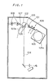
- Fig. 1 is a sectional view of a conventional image recorder.
- the conventional image recorder includes a pair of introduction rollers 101.
- the introduction rollers hold a leading edge portion of a film drawn out of a roll 105.
- a film 103 is drawn out of the roll 105 as the introduction rollers rotate.
- a main roller 102 rotates while holding the film 103 in cooperation with nip rollers 106, whereby the film 103 is fed in the feed scanning direction.
- a laser beam 104 scans the advancing film 103 in the primary scanning direction, the scanning being synchronized with the feeding of the film 103. Hence, an image is reproduced on the film 103.
- the film 103 is loosened between the introduction rollers 101 and the main roller 102 while a leading edge portion 103a of the exposed film 103 being downwardly pulled. This protects the film 103 from undesirable tension which causes the film 103 to slip on the main roller 102. Consequently, image recording is attained which is free from slippage of the film 103 on the main roller 102 as described above.
- the main roller 102 rotates counter-clockwise to rewind the exposed film 103.
- the main roller 102 once again rotates, this time in the clockwise direction, thereby to allow the film 103 to advance a desired distance toward a cutter 107 and guide rollers 108, so that the cutter 107 cuts off the film 103.
- a film sheet thus obtained has a desirable length and a reproduced image recorded thereon.
- the conventional image recorder employs a guiding unit 109 for preventing the film 103 from forming a loop.
- the image recorder also employs a switching unit for changing the feed direction. The switching unit changes the feed direction of the film 103 toward a downward direction or toward a direction to the cutter 107.
- time required for obtaining one film sheet, or a cycle time becomes long. This will eventually deteriorate the production efficiency of the image recorder.
- the present invention is directed to an image recorder.
- the image recorder comprises: means for feeding a photosensitive material in a first direction; means for loosening the photosensitive material in a second direction approximately perpendicular to the first direction, the loosening means being positioned downstream from the feeding means relative to said first direction; means, disposed between the feeding means and the loosening means, for cutting off the photosensitive material, whereby a sheet of photosensitive material is cut off from the photosensitive material, the photosensitive material sheet being of a predetermined length; and means for recording an image to be reproduced onto the photosensitive material sheet.
- the present invention is also directed to a method of recording an image onto a photosensitive material sheet.
- the method includes: feeding a photosensitive material in a first direction by a predetermined length; holding a leading edge portion of the fed photosensitive material; loosening the photosensitive material to thereby form a loop of the photosensitive material, a size of the loop being corresponding to a length of a photosensitive material sheet to be recorded; cutting off the photosensitive material at a cutting position, the cutting position being located upstream from the loop relative to the first direction, whereby a photosensitive material sheet is cut off from the photosensitive material; and recording an image to be reproduced onto the photosensitive material sheet.
- the present invention is also directed to means for urging a photosensitive material toward a main roller.
- the means comprises: a body; a pair of nip roller extending in parallel to the main roller; a first and a second supporting members for supporting the nip rollers, the first supporting member being close to one end of the main roller, the second supporting member being close to another end of the main roller; and a mechanism, coupled to the first and the second supporting members, for moving the first and the second supporting members toward the main roller so that the nip rollers are brought into a contact with the main roller in order.
- an object of the present invention is to provide an image recorder in which a photosensitive material is stably fed.
- Another object is to provide an image recorder in which time required for recording an image onto a photosensitive material sheet is reduced.
- Another object is to provide an image recorder which prevents a photosensitive material from dropping into the image recorder.
- Another object is to improve means for urging a photosensitive material toward a main roller, which is required to bring a photosensitive material into contact with the main roller.
- the photosensitive material is cut off by the cutting means prior to image recording by means of the recording means thereby to produce a sheet of a preset length, whereafter an image is reproduced on the sheet. Therefore, a sheet needs not to be fed in a counter feed scanning direction after exposure thereon.
- This allows the novel image recorder to omit a unit which is indispensable for a conventional image recorder to reversely feed a film. Hence, a simple structure image recorder with a short cycle time can be attained.
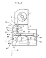
- Figs. 2 and 3 are a schematic side view and a perspective view of an image recorder according to the first embodiment of the present invention, respectively.
- a laser beam L3 scans a film F in the primary scanning direction X which is approximately perpendicular to the feed scanning direction Y while the film F is fed in the feed scanning direction Y, whereby a reproduced image is recorded onto the film F.
- the image recorder comprises: a body 5; an introduction roller unit 10 for drawing the film F out of a film case 1 and feeding the film F in the feed scanning direction Y; a cutter unit 20 for cutting the film F; a travel roller unit 30 for loosening the film F in the direction Z approximately perpendicular to both the primary scanning direction X and the feed scanning direction Y; an expose-scanning unit 40 for sweeping the laser beam in the primary scanning direction X as the film F is fed in the feed scanning direction Y, thereby to record a reproduced image onto the film F; and a carrier unit 70 for carrying the film F, which has the reproduced image recorded thereon, out of the body 5.
- the image recorder also comprises a control unit not shown. The control unit governs the image recorder overall according to signals from various sensors of respective units thereof and/or to instructions from an operation panel not shown.
- the top frame of the body 5 has an opening 6 whose position precisely corresponds to the film case 1.
- the film F is drawn off the film case 1 disposed above the body 5, and then is guided into the body 5 through the opening 6.
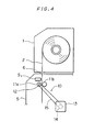
- Fig. 4 is an enlarged view of the introduction roller unit 10.
- the introduction roller unit 10 is disposed just below the opening 6 of the body 5.
- a pair of introduction rollers 11a and 11b are mounted for rotation on the body 5 just below the opening 6.
- a lever not shown is connected to the introduction rollers 11a and 11b, so that the introduction rollers 11a and 11b are contacted with or separated from each other by operation of the lever.
- a pulley 12 is linked to the introduction roller 11a, while another pulley 14 is mounted to a rotary shaft of a motor 13 which is fixed to the body 5.
- a belt 15 is then stretched about the pulleys 12 and 14.
- the driving force of the motor 13 is transmitted to the introduction roller 11a, and the introduction rollers 11a and 11b, holding the introduced film F in their tight contact with each other, so as to feed the film F in the feed scanning direction Y according to rotation of the motor 13.
- a check sensor S1 is located between the opening 6 and the introduction roller 11a to sense the introduction of the film F into the body 5.
- the cutter unit 20 which is attached to the body 5 just below the introduction rollers 11a and 11b (see Fig. 2), includes a pair of cutters 21 and 21, and a cutter driving device not shown for driving the cutters 21 and 21.
- a width detection sensor group S2 for detecting a width of the film F.
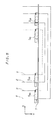
- Fig. 5 is a plan view of the width detection sensor group S2.
- the width of the film F is 6 inches (dotted line), 8 inches (dash-and-dot line), 10 inches (dash-and-two-dot line) or 12 inches (dash-and-three-dot line), in general.
- width detection sensors S21, S22, S23 and S24 are arranged at regular intervals on a supporting member 7, which is fixed to the body 5, to detect the respective four widths.
- the width of the film F is automatically determined as 8 inches.
- the travel roller unit 30 is attached adjacent to the width detection sensor group S2.
- the travel roller unit 30 includes a guiding plate 31 fixed to the body 5 just below the width detection sensor group S2.
- the travel roller unit 30 also includes a guiding roller 32 mounted for rotation on the body 5 such that it faces the guiding plate 31.
- the film F advances between the guiding plate 31 and the guiding roller 32.
- a travel guide 33 is fixed to the body 5 below the guiding plate 31 and the guiding roller 32 in such a manner that it extends in the direction Z.
- a travel roller 34 is guided by the travel guide 33 and slides in the direction Z along the travel guide 33.
- a main roller 41 of the expose-scanning unit 40 is mounted close to the travel roller unit 30 for rotation on the body 5.
- a nip roller unit A for urging the film toward the main roller is provided adjacent to the main roller 41.
- the nip roller unit A includes a pair of nip rollers 42a and 42b which face the main roller 41.
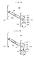
- Figs. 6A and 6B are schematic views of the nip roller unit, the former being not urging the film toward the main roller 41, whereas the latter being urging the film toward the main roller 41.
- the nip rollers 42a and 42b are rotatably supported at a preset interval to two trapezoidal supporting members 43, and can be brought into contact with or separated from the main roller 41.
- the nip rollers 42a and 42b are each parallel to the main roller 41.
- the two trapezoidal members 43 are close to the end portions of the main roller 41 and facing each other, and are carrying the nip rollers 42a and 42b in a manner that they sandwich the nip rollers 42a and 42b.
- One end portion 43a of the supporting member 43 is linked to an end of a first spring 44 which has its another end fixed to the body 5.
- Another end portion 43b of the supporting member 43 is linked to an end of a second spring 45 whose another end is also fixed to the body 5.
- the first and the second spring 44 and 45 apply pulling force to the supporting member 43 so that the supporting member 43 mvoes toward the main roller 41.
- the first spring posesses pulling force greater than that of the second spring 45.
- An end portion 46a of an operation member 46 is linked for rotation to the approximately center portion of the supporting member 43 through a pin 43c, while the approximately center portion 46b of the operation member 46 is supported for rotation to the body 5.
- the supporting member 43 moves toward and away from the main roller 41 according to clockwise and counter-clockwise rotation of the operation member 46 about the approximately center portion 46b.
- An eccentric cam 47 is so positioned that it cotacts with another end portion 46c of the operation member 46.
- the first and the second springs 44 and 45 urge the end portion 46c of the operation member 46 into engagement with the cam surface 47a, so that eccentric rotation of the eccentric cam 47 adjusts the position of the operation member 46 which is in rotation.
- the operation member 46 is greately biased counter-clockwise about the approximately center portion 46b. This in turn allows the supporting member 43, which is linked to the end portion 46a of the operation member 46, to move to the left against the force of the first and the second springs 44 and 45. Accordingly, the nip rollers 42a and 42b are separated from the main roller 41.
- the supporting member 43 is inclined at an angle of 5 degrees with respect to the feed scanning direction Y inasmuch as the pulling force of the first spring 44 is greater than that of the second spring 45 as mentioned earlier. This permits the nip roller 42a to be nearer (even though slightly) the main roller 41 than the nip roller 42b.
- a scanning unit 50 of the expose-scanning unit 40 includes a laser source 51.
- a laser beam L1 leaving the laser source 51 impinges onto an acousto-optic modulating element 54 through mirrors 52 and 53.
- the acousto-optic modulating element 54 turns the laser beam L1 on-off in response to a control signal which corresponds to an image to be recorded.
- a laser beam L2 thus modulated by the acousto-optic modulating element 54 is then via a mirror 55 transmitted to a deflecting unit, i.e., a galvanometer mirror 56.
- a deflected laser beam L3 is finally focused by an f ⁇ lens 57 upon a surface of the film F on the main roller 41.
- a side frame of the body 5 has an opening 8 for guiding the laser beam L3 from the scanning unit 50 into the body 5.
- a mechanical shutter 58 is on the optical path of the laser beam L3 (Fig. 2).
- Figs. 7A and 7B are perspective views of the mechanical shutter 58.
- Fig. 7A shows the mechanical shutter as it is closed whereas Fig. 7B showing the same as it is open.
- a member 59 shaped in an approximately cylinder is supported for rotation by holders 60 and 61 each of which is secured to the body 5.
- the cylindrical member 59 has a slit 59a which corresponds to a scanning area of a laser beam.
- the cylindrical member 59 is connected on its one end to a slit driving unit 62.
- the slit driving unit 62 drives the cylindrical member 59 into rotation.
- the slit 59a is positioned on-off the optical path of the laser beam L3.
- the slit driving unit 62 is provided with a plate 63 which is fixed at one end of the cylindrical member 59.
- the plate 63 is in turn connected in its upper right portion to an end of a third spring 64 which is linked to a fixed pin 65 laterally projecting from the supporting member 60.
- the plate 63 is connected in its lower right portion to an end of a fourth spring 66 which is in turn linked to a movable pin 67a mounted to a solenoid 67.
- the slit driving unit cited above is not proposed in an exclusive sense.
- a motor or an air cylinder etc. is also a possible substitute for driving the cylindrical member 59.
- a member shaped in a polygonal prism may of course be used in place of the cylindrical member 59.
- Figs. 8A and 8B are sectional views of the carrier unit 70, which is disposed near the main roller 41.
- the carrier unit 70 is provided with a lower guide plate 71 which is W-shaped in section.
- An upper guide plate 72 is attached to the body 5 so as to face the lower guide plate 71.
- the film F is guided to a pair of first carrier rollers 73a, 73b through a path between the upper and the lower guide plate 72 and 71.
- the upper and the lower guide plate 72 and 71 have through holes 72a and 71a, respectively.
- An upper plate 74 is rotatably mounted such that it rotates about a pin 75 by its own weight.
- a slope guide plate 76 is mounted for rotation about a shaft 77 corresponding to the through hole 71a.
- a slope guide plate driving device is connected to the shaft 77. The slope guide plate 76 is rotated about the shaft 77 by the slope guide plate driving device, whereby a path of the film F is altered depending on necessity.
- the carrier unit 70 comprises a pair of second carrier rollers 78a, 78b.
- Pulleys 79 and 80 are secured to the rotation shafts of the first and the second carrier roller 73a and 78a, respectively.
- a pulley 82 is mounted to a rotary shaft 81a of a motor 81.
- a belt 83 runs over the pulleys 79, 80 and 82 so that the first and the second carrier roller 73a and 78a are driven by the motor 81.
- an operator disposes the film case 1 containing a proper size film F in the form of a roll, e.g., an eight-inch-width film F, in a preset position above the body 5. Then, the operator turns a knob (not shown) linked to the reel of the film roll F in order to guide the film F into the body 5 through the opening 6.
- the introduction rollers 11a and 11b are not contacting each other during the introduction of the film F into the body 5. This allows the film F to advance between the rollers 11a and 11b and further between the cutters 21 and 21.
- the width detection sensors S21 and S22 turn on, so that a light emitting diode provided in the body 5 is turned on.
- the controller not shown receives signals from the width detection sensors S21 and S22, and the memory thereof (not shown) stores the data of the width of the film F (8 inches).
- the width detection sensor group S2 automatically detects the width of the film F set into the image recorder; in consequence, incorrect data concerning the width of the film cannot be inadvertently entered. More particularly, when an operator enters film width data in a memory through an operation panel or the like in the current technique, he sometimes enters incorrect film width data during this manual work. However, such an error is completely avoided according to this embodiment.
- the image recorder according to the present invention is superior to conventional image recorders.
- the operator stops operating the knob. Then, the operator brings the introduction rollers 11a and 11b into contact by operating the lever, whereby the film F is held between the introduction rollers 11a and 11b. Thus, the eight-inch-wide film F is mounted to the image recorder.
- the control unit starts governing operations of the respective units of the image recorder in order to record an image to be reproduced onto the film F.
- Figs. 9A and 9B are flow charts of operations of the image recorder.
- the initial condition being: the travel roller 34 is placed in its initial position (left end position of Fig. 2); the nip rollers 42a and 42b are each separated from the main roller 41 as in Fig. 6A; and the slit 59a of the cylindrical member 59 is off the optical path of the laser beam L3, blocking off the laser beam L3.
- a display of the control unit (not shown) gives a message alarming that the initial condition is not satisfied (STEP ST2).
- control unit orders the motor 13 (see Fig. 4) to rotate the introduction roller 11a. This allows the film F to be fed in the feed scanning direction Y (STEP ST3).
- the film F advances between the main roller 41 and the nip rollers 42a and 42b.
- the control unit orders the motor 13 to stop. This consequently stops the feeding of the film F (STEP ST5).
- the nip rollers 42a and 42b move toward the main roller 41 to press the film F against the main roller 41 (STEP ST6).
- the eccentric cam 47 rotates 180 degrees clockwise from its position of Fig. 6A in response to an instruction from the control unit.
- the force of the springs 44 and 45 urge the operation member 46 to follow the movement of the cam surface 47a.
- the operation member 46 rotates clockwise about the center portion 46b. This allows the supporting member 43 linked to the operation member 46 to approach the main roller 41 in a manner that the supporting member 43 is inclined at an angle of around 5 degree with respect to the feed scanning direction Y.
- the nip roller 42a tightly contacts the main roller 41, pressing the film F against the surface of the main roller 41 on the point P1 of Fig. 6C.
- the nip roller 42b is close to (even though spaced a certain distance away from) the main roller 41 (see Fig. 6C), pushing the leading edge portion of the film F to the right against the force of the film F to bend to the left. This brings the film F into approximately perfect contact with the main roller 41 between the points P1 and P2.
- the supporting member 43 rotates counter-clockwise as in Fig. 6C, whereby the nip roller 42b moves toward the main roller 41 while urging the leading edge portion of the film F against the main roller 41.
- the nip roller 42a hardly move during the rotation of the the eccentric cam 47 since the presense of the main roller 41 restricts the position of the nip roller 42a.
- the nip roller 42a is applying tension to the film F which is being urged against the main roller 41.
- the tension pulls the film F in a direction approximately opposite to the feed scanning direction (-Y).
- This counter feed scanning direction (-Y) is extending along the circumference of the main roller 41.
- the film F is provided with the tension in the counter feed scanning direction (-Y) while the leading edge portion thereof being gradually urging against the main roller 41 as follows: a point on which the film F contacts the main roller 41 successively moves from the point P2 to the point P n until the nip roller 42b finally contacts the main roller 41.
- the introduction roller 11a thereafter once again rotates, feeding the film F in the feed scanning direction Y.
- the travel roller 34 moves in the Z-direction.
- a film loop is formed as desired within the travel roller unit 30 (STEP ST7).
- the introduction roller 11a keeps rotating until an accumulated cycle value of the introduction roller 11a or the motor coincides with the value in correspondence with the loop size previously entered. On the contrary, if size data of the desired loop is not entered beforehand, the introduction roller 11a will stop rotating at the time the film F has fed an initially determined length.
- the cutter driving device is actuated responsive to an instruction received from the control unit.
- the cutters 21, 21 close and cut off the film F (STEP ST8), whereby a sheet of eight-inch-wide film of a desired length is produced (hereinafter referred to only as a "sheet").
- a sheet length is precisely and simply adjusted by merely adjusting a size of a loop which is formed as beforehand described.
- the present image recorder enables a reduced size image recorder. The reason is as follows: It is assumed that a rather long sheet is wanted. In an image recorder without the travel roller unit 30, the main roller 41 and a pair of cutters 21 and 21 must be spaced apart a distance which corresponds to the length of the wanted sheet. This is unneccesary if an image recorder has the travel roller unit 30.
- the shutter 58 opens (STEP ST9).
- the movable pin 67a of the solenoid 67 withdraw to its position shown in Fig. 7B from its position shown in Fig. 7A in response to an instruction from the control unit.
- the cylindrical member 59 rotates clockwise.
- the slit 59a is thus provided on the optical path of the laser beam L3 (Fig. 7B).
- the slope guide plate 76 swings upward as shown in Fig. 8A (STEP ST10).
- the main roller 41 and the first and the second carrier roller 73a and 78a simultaneously rotate, accordingly the sheet F is fed in the feed scanning direction Y (STEP ST11).
- the laser beam L3 which was modulated in the scanning unit 50 according to an image signal from the control unit, scans the sheet through the shutter 58 in the primary scanning direction X.
- an image is recorded on the sheet.
- the sheet sequentially forwarded in the sub scanning direction Y by the main roller 41, is conveyed through a path defined between the upper guide plate 72 and the slope guide plate 76 toward the first carrier rollers 73a, 73b, hence pushing up the upper plate 74.
- a loop detection sensor not shown installed in the vicinity of the upper plate 74 detects that the upper plate 74 has been pushed up (STEP ST12)
- the slope guide plate 76 retracts into its position of Fig. 8B (STEP ST13).
- the sheet from the main roller 41 will move toward the first carrier rollers 73a, 73b along the lower guide plate 71. Hence, the sheet is loosened between the main roller 41 and the first carrier rollers 73a, 73b while being transported from the main roller 41 to the first carrier rollers 73a, 73b.
- the film F is cut at a preset position into a desired length sheet (STEP ST8) prior to image recording onto the same, and the sheet is loosened within the carrier unit 70 during conveyance thereof by the carrier unit 70.
- the sheet would not slip between the main roller 41 and the nip rollers 42a and 42b, which would eventually enable stable feeds.
- the sheet thus delivered to the first carrier rollers 73a, 73b is then carried out of the image recorder by the second carrier rollers 78a, 78b.
- an end sensor S4 is installed between the first carrier rollers 73a, 73b and the second carrier rollers 78a, 78b.
- the end sensor S4 keeps detecting the presence of the sheet until the sheet has been carried out of the image recorder.
- the control unit discharges a signal upon a lapse of a preset period of time after the tail edge of the sheet has passed under the end sensor S4 toward the second carrier rollers 78a, 78b (STEP ST14), in order to stop the main roller 41 as well as the first and second carrier rollers 73a and 78a (STEP ST15). Then, the shutter 58 closes and the travel roller 34 retracts into its initial position, and concurrently the nip rollers 42a and 42b are released (STEP ST16).
- the eccentric cam 47 is driven to eccentrically rotate 180 degrees counter-clockwise from its position of Fig. 6B in response to an instruction from the control unit. This allows the supporting member 43 linked to the end portion 46a of the operation member 46 to move to the left against the force of the springs 44 and 45, whereby the nip rollers 42a and 42b are separated from the main roller 141.
- the film F is cut off by the cutters 21 and 21 prior to image recording by means of the expose-scanning unit 40 (STEP ST8) thereby to produce a sheet of a preset length, whereafter an image is reproduced on the sheet. Therefore, a sheet needs not to be fed in a counter feed scanning direction after exposure thereon.
- This allows the novel image recorder to omit a unit which is indispensable for a conventional image recorder to reversely feed a film. Hence, a simple structure image recorder with a short cycle time can be attained.
- the image recorder of the present invention has a "head-cutting" function as explained in the following:
- Figs. 10A and 10B are flow charts explaining "head-cutting".
- a display of a control unit shows a message asking the operator whether the image recorder proceeds to "head-cutting" or not (STEP ST12). If the operator decides not to perform "head-cutting” and pushes a start switch of the control unit, the image recorder starts consecutive production of sheets which have an image reproduced thereon.
- the film F starts to be fed in the feed scanning direction Y while being held between introduction rollers 11a and 11b.
- the film F is stopped when the leading edge portion (i.e., the head portion) thereof reaches a position between a main roller 41 and nip rollers 42a and 42b (STEP ST 22).
- the cutter driving device drives so that the cutters 21 and 21 close. Accordingly, the film F is cut off (STEP ST26) and a partially exposed sheet is produced.
- the slope guide plate 76 swings upward (STEP ST27, Fig. 8A), and the main roller 41 and the first and the second carrier rollers 73a and 78a start rotating simulatenously. This permits the sheet, which is being held between the main roller 41 and the nip rollers 42a and 42b, to follow the path between the upper guide plate 72 and the slope guide plate 76 toward the first carrier rollers 73a, 73b.
- the sheet thus conveyed to the first carrier rollers 73a, 73b is finally carried out of the image recorder through second carrier rollers 78a, 78b.
- the end sensor S4 keeps detecting the presense of the sheet during this stage.
- the tail edge of the sheet passes under an end sensor S4 toward the second carrier rollers 78a, 78b at a certain point (STEP ST29).
- the main roller 41 and the first and second carrier roller 73a and 78a stop rotating (STEP ST30).
- the present invention solves still another problem, namely, the problem regarding film drop.
- the problem and the solution thereof will now be described.
- the tail edge of a long film F is not fixed to a reel, and the film F is only rolled around the reel in the form of a roll. If a length of film roll left in the film case is shorter than a length of a film to be fed (i.e., the feed length), the tail edge portion of the remaining film loses its contact with the reel while being fed toward a main roller by introduction rollers. This causes the tail edge portion to pass the introduction rollers before nip rollers hold the leading edge portion of the remaining film against the main roller. In other words, the film fails to be held by the rollers and drops within the image recorder. This would often cause a trouble. In order to solve this problem, an image recorder embodied by the first embodiment is improved (described later).
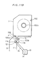
- Figs. 11A and 11B are partially enlarged views of the improved image recorder according to the third embodiment.
- the improved image recorder has an opening 106 on its top frame (Fig. 11A).
- the opening 106 is placed correspondingly to the position of a film case 1 which is mounted above a body 5.
- the film F is drawn out of a roll 102 and then is introduced into the body 5 through the opening 106.
- Sloping guide plates 105a and 105b are provided around the opening 106 in the body 5.
- a pair of introduction rollers 11a and 11b are mounted for rotation to the body 5 just beneath the sloping guide plates 105a and 105b.
- a sensor for detecting tail edge portion S1 is mounted on the sloping guide plate 105b which is between the opening 106 and the introduction roller 11b (Fig. 11A).
- the sensor S1 includes a laser beam projector and a laser beam receiver. While the film F is at a postion corresponding to the sensor S1, therefore, a laser beam from the laser beam projector is reflected at the back surface of the film F and enters the laser beam receiver.
- the laser beam receiver keeps providing a detection signal to a control unit as far as it receives a reflected laser beam. As a result, the tail edge portion of the film F is detected by the sensor S1.
- the tail edge portion (i.e., F') of the film loses its contact with the reel 102a before passing the sensor S1 (Fig. 11B). To make the matters even worse, the tail edge portion F' often passes the introduction rollers 11a and 11b before the nip rollers 42a and 42b hold the leading edge portion of the film F against the main roller 41.
- the film F drops within the image recorder by its own weight.
- the sensor for detecting tail edge portion S1 is employed in order to prevent such a problem.
- Step ST3 a portion of the film F has been already located at the position corresponding to the sensor S1 (Fig. 11A). Hence, a laser beam from the laser beam projector of the sensor S1 is reflected at the back surface of the film F, and the reflected laser beam receiver receives the same. Thus, the sensor S1 detects the presense of the film F and sends a detection signal to the control unit.
- Step ST3 is carried out.
- the introduction rollers 11a and 11b start feeding the film F in the feed scanning direction.
- the sensor S1 continuously detects the presense of the film F. If the tail edge portion F' passes the sensor S1 during the feeding by means of the introduction rollers 11a and 11b (Fig. 11B), a laser beam from the laser beam projector of the sensor S1 will fail to be reflected at the back surface of the film F, whereby the sensor S1 detects that the tail edge portion F' has passed the same.
- a sub control unit gives an instruction to the motor for driving introduction roller 11a and deactivates the same, to stop rotation of the introduction roller 11a (Fig. 11B).
- the introduction rollers 11a and 11b hold the film F in the vicinity of the tail edge portion F' (Fig. 11B), whereby the film F is prevented from dropping.
- a display not shown of the main control unit gives a message informing the holding of the remaining film as soon as the introduction roller 11a stops.
- the sub control unit operates the motor for driving introduction roller 11a to reversely rotate.
- the remaining film F is drawn out of the body 5, i.e., out of the image recorder, through opening 106.
- the image recorder employs a so called reflecting type sensor as the sensor S1 for detecting a tail edge portion. Still, it will be appreciated that this choice is not limiting. A transmitting type sensor, for example, is also employable.
- Step ST7 for forming a loop when amount of remaining film is very small, the tail edge portion F' often loses its contact with the reel 102a as the film F is fed by the introduction rollers 11a and 11b, and passes the sensor for detecting tail edge portion S1 (Fig. 11B). Even in this case, the nip rollers 42a and 42b prevent the film F from dropping since they are holding the leading edge portion of the film F against the main roller 41.
- the introduction roller 11a does not have to stop rotating every time the sensor S1 detects the tail edge portion F'. However, it is likely that the film does not have a predetermined length required for image recording. In order to draw the film F out of the image recorder, the introduction roller 11a may stop rotating concurrently with the detection of the tail edge portion F' by the sensor S1, so that in response to an operator's instruction the nip rollers 42a and 42b are separated from the main roller 41 and the introduction roller 11a is rotated.
- the nip roller 42a is urged toward the main roller 41 before the nip roller 42b is; however, it is appreciated that executing this operation vice versa does not lessen the effect of the embodiments.
Abstract
Description
- This invention relates to an image recorder, such as a flat-bed type color scanner, for recording an image to be reproduced onto a photosensitive material sheet. In the image recorder, a photosensitive material is drawn out of a roll of photosensitive material, and then is fed in the feed scanning direction while being scanned by a laser beam in the primary scanning direction, which is approximately perpendicular to the feed scanning direction, whereby the image is recorded onto the photosensitive material.
- In an image recorder of this type, a long photosensitive film (hereinafter referred as a "film") is stored in the form of a roll and is accommodated within a film case. A film drawn out of the film case is held between a main roller and nip rollers. The film is fed in the feed scanning direction as the main roller rotates. The image recorder comprises an expose-scanning unit. The expose-scanning unit sweeps a laser beam across a film in the primary scanning direction in synchronism with a feeding of the film in the feed scanning direction thereby to record an image onto the film. The recorded film is further fed by a desired length in the feed scanning direction, and thereafter automatically cut off by a cutter located in the image recorder. Thus, a desirable length film sheet with the image reproduced thereon is obtained.
- As well known in the art, stable and smooth feeding of the film in the feed scanning direction is indispensable for recording an excellent quality image. In the image recorder as above, the film is fed from the film case as the main roller rotates while being held by a pair of introduction rollers. This causes the film to be in tension in the reverse direction to the feed scanning direction and hence to slip between the main roller and the nip rollers, often resulting in unstable feeds. Force required to draw the film out of the roll, in particular, changes according to amount of remaining film in the roll. Thus, changes in amount of the remaining film exert influence on the feeding of the film.
- Various techniques have been proposed to overcome the problems described above, one of them being an image recorder of Japanese Patent Laid-Open Gazette No. 63-71061.
- Fig. 1 is a sectional view of a conventional image recorder. The conventional image recorder includes a pair of
introduction rollers 101. The introduction rollers hold a leading edge portion of a film drawn out of aroll 105. Afilm 103 is drawn out of theroll 105 as the introduction rollers rotate. Amain roller 102 rotates while holding thefilm 103 in cooperation withnip rollers 106, whereby thefilm 103 is fed in the feed scanning direction. Alaser beam 104 scans the advancingfilm 103 in the primary scanning direction, the scanning being synchronized with the feeding of thefilm 103. Hence, an image is reproduced on thefilm 103. In this image recorder, thefilm 103 is loosened between theintroduction rollers 101 and themain roller 102 while a leadingedge portion 103a of the exposedfilm 103 being downwardly pulled. This protects thefilm 103 from undesirable tension which causes thefilm 103 to slip on themain roller 102. Consequently, image recording is attained which is free from slippage of thefilm 103 on themain roller 102 as described above. - After the image recording, the
main roller 102 rotates counter-clockwise to rewind the exposedfilm 103. Themain roller 102 once again rotates, this time in the clockwise direction, thereby to allow thefilm 103 to advance a desired distance toward acutter 107 andguide rollers 108, so that thecutter 107 cuts off thefilm 103. A film sheet thus obtained has a desirable length and a reproduced image recorded thereon. - Yet, there arise several other problems as follows:
While the film is fed backward, the film tends to be folded between themain roller 102 and either theintroduction rollers 101 or afilm case 105a, so that an unexpected loop is formed. In order to overcome this problem, the conventional image recorder employs a guidingunit 109 for preventing thefilm 103 from forming a loop. The image recorder also employs a switching unit for changing the feed direction. The switching unit changes the feed direction of thefilm 103 toward a downward direction or toward a direction to thecutter 107. In addition, since thefilm 103 must be fed backward after being exposed, time required for obtaining one film sheet, or a cycle time, becomes long. This will eventually deteriorate the production efficiency of the image recorder. - The present invention is directed to an image recorder. The image recorder comprises: means for feeding a photosensitive material in a first direction; means for loosening the photosensitive material in a second direction approximately perpendicular to the first direction, the loosening means being positioned downstream from the feeding means relative to said first direction; means, disposed between the feeding means and the loosening means, for cutting off the photosensitive material, whereby a sheet of photosensitive material is cut off from the photosensitive material, the photosensitive material sheet being of a predetermined length; and means for recording an image to be reproduced onto the photosensitive material sheet.
- The present invention is also directed to a method of recording an image onto a photosensitive material sheet. The method includes: feeding a photosensitive material in a first direction by a predetermined length; holding a leading edge portion of the fed photosensitive material; loosening the photosensitive material to thereby form a loop of the photosensitive material, a size of the loop being corresponding to a length of a photosensitive material sheet to be recorded; cutting off the photosensitive material at a cutting position, the cutting position being located upstream from the loop relative to the first direction, whereby a photosensitive material sheet is cut off from the photosensitive material; and recording an image to be reproduced onto the photosensitive material sheet.
- The present invention is also directed to means for urging a photosensitive material toward a main roller. The means comprises: a body; a pair of nip roller extending in parallel to the main roller; a first and a second supporting members for supporting the nip rollers, the first supporting member being close to one end of the main roller, the second supporting member being close to another end of the main roller; and a mechanism, coupled to the first and the second supporting members, for moving the first and the second supporting members toward the main roller so that the nip rollers are brought into a contact with the main roller in order.
- Accordingly, an object of the present invention is to provide an image recorder in which a photosensitive material is stably fed.
- Another object is to provide an image recorder in which time required for recording an image onto a photosensitive material sheet is reduced.
- Another object is to provide an image recorder which prevents a photosensitive material from dropping into the image recorder.
- Another object is to improve means for urging a photosensitive material toward a main roller, which is required to bring a photosensitive material into contact with the main roller.
- According to the present invention, the photosensitive material is cut off by the cutting means prior to image recording by means of the recording means thereby to produce a sheet of a preset length, whereafter an image is reproduced on the sheet. Therefore, a sheet needs not to be fed in a counter feed scanning direction after exposure thereon. This allows the novel image recorder to omit a unit which is indispensable for a conventional image recorder to reversely feed a film. Hence, a simple structure image recorder with a short cycle time can be attained.
- These and other objects, features, aspects and advantages of the present invention will become more apparent from the following detailed description of the present invention when taken in conjunction with the accompanying drawings.
-
- Fig. 1 is a sectional view of a conventional image recorder.
- Figs. 2 and 3 are a schematic side view and a perspective view of an image recorder according to the first embodiment of the present invention, respectively;
- Fig. 4 is a schematic sectional view of an introduction roller unit;
- Fig. 5 is a side view of a width detection sensor group;
- Figs. 6A and 6B are schematic views of a nip roller unit for urging a film against a main roller;
- Fig. 6C is an enlarged detail view showing operation of the nip roller unit;
- Figs. 7A and 7B perspective views of a machine shutter;
- Figs. 8A and 8B are sectional views of a carrier unit;
- Figs. 9A, 9B, 10A and 10B are flow charts of operations of the image recorder, respectively; and
- Figs. 11A and 11B are partially enlarged views of an image recorder according to the third embodiment.
- Figs. 2 and 3 are a schematic side view and a perspective view of an image recorder according to the first embodiment of the present invention, respectively.
- In this novel image recorder, a laser beam L₃ scans a film F in the primary scanning direction X which is approximately perpendicular to the feed scanning direction Y while the film F is fed in the feed scanning direction Y, whereby a reproduced image is recorded onto the film F.
- The image recorder comprises: a
body 5; anintroduction roller unit 10 for drawing the film F out of afilm case 1 and feeding the film F in the feed scanning direction Y; acutter unit 20 for cutting the film F; atravel roller unit 30 for loosening the film F in the direction Z approximately perpendicular to both the primary scanning direction X and the feed scanning direction Y; an expose-scanningunit 40 for sweeping the laser beam in the primary scanning direction X as the film F is fed in the feed scanning direction Y, thereby to record a reproduced image onto the film F; and acarrier unit 70 for carrying the film F, which has the reproduced image recorded thereon, out of thebody 5. The image recorder also comprises a control unit not shown. The control unit governs the image recorder overall according to signals from various sensors of respective units thereof and/or to instructions from an operation panel not shown. - As in Fig. 2, the top frame of the
body 5 has anopening 6 whose position precisely corresponds to thefilm case 1. The film F is drawn off thefilm case 1 disposed above thebody 5, and then is guided into thebody 5 through theopening 6. - Fig. 4 is an enlarged view of the
introduction roller unit 10. Theintroduction roller unit 10 is disposed just below theopening 6 of thebody 5. To be precise, a pair ofintroduction rollers body 5 just below theopening 6. A lever not shown is connected to theintroduction rollers introduction rollers - A
pulley 12 is linked to theintroduction roller 11a, while anotherpulley 14 is mounted to a rotary shaft of amotor 13 which is fixed to thebody 5. Abelt 15 is then stretched about thepulleys motor 13 is transmitted to theintroduction roller 11a, and theintroduction rollers motor 13. - A check sensor S₁ is located between the
opening 6 and theintroduction roller 11a to sense the introduction of the film F into thebody 5. - The
cutter unit 20, which is attached to thebody 5 just below theintroduction rollers cutters cutters - Provided just below the
cutter unit 20 is a width detection sensor group S₂ for detecting a width of the film F. Fig. 5 is a plan view of the width detection sensor group S₂. The width of the film F is 6 inches (dotted line), 8 inches (dash-and-dot line), 10 inches (dash-and-two-dot line) or 12 inches (dash-and-three-dot line), in general. In this embodiment, as shown in Fig. 5, width detection sensors S₂₁, S₂₂, S₂₃ and S₂₄ are arranged at regular intervals on a supportingmember 7, which is fixed to thebody 5, to detect the respective four widths. - For instance, when the leading edge portion of an eight-inch-wide film F reaches the position corresponding to the width detection sensor group S₂ as shown by dash-and-dot line in Fig. 4, the two detection sensors S₂₁ and S₂₂ are only turned on sending signals to the control unit. Thus, the width of the film F is automatically determined as 8 inches.
- As seen in Fig. 2, the
travel roller unit 30 is attached adjacent to the width detection sensor group S₂. Thetravel roller unit 30 includes a guidingplate 31 fixed to thebody 5 just below the width detection sensor group S₂. Thetravel roller unit 30 also includes a guidingroller 32 mounted for rotation on thebody 5 such that it faces the guidingplate 31. Thus, the film F advances between the guidingplate 31 and the guidingroller 32. - A
travel guide 33 is fixed to thebody 5 below the guidingplate 31 and the guidingroller 32 in such a manner that it extends in the direction Z. Atravel roller 34 is guided by thetravel guide 33 and slides in the direction Z along thetravel guide 33. - A
main roller 41 of the expose-scanningunit 40 is mounted close to thetravel roller unit 30 for rotation on thebody 5. A nip roller unit A for urging the film toward the main roller is provided adjacent to themain roller 41. The nip roller unit A includes a pair of niprollers main roller 41. - Figs. 6A and 6B are schematic views of the nip roller unit, the former being not urging the film toward the
main roller 41, whereas the latter being urging the film toward themain roller 41. - In the nip roller unit A, the nip
rollers trapezoidal supporting members 43, and can be brought into contact with or separated from themain roller 41. The niprollers main roller 41. - The two
trapezoidal members 43 are close to the end portions of themain roller 41 and facing each other, and are carrying the niprollers rollers - One
end portion 43a of the supportingmember 43 is linked to an end of afirst spring 44 which has its another end fixed to thebody 5. Anotherend portion 43b of the supportingmember 43 is linked to an end of asecond spring 45 whose another end is also fixed to thebody 5. Thus, the first and thesecond spring member 43 so that the supportingmember 43 mvoes toward themain roller 41. The first spring posesses pulling force greater than that of thesecond spring 45. - An end portion 46a of an
operation member 46 is linked for rotation to the approximately center portion of the supportingmember 43 through apin 43c, while the approximatelycenter portion 46b of theoperation member 46 is supported for rotation to thebody 5. Thus, the supportingmember 43 moves toward and away from themain roller 41 according to clockwise and counter-clockwise rotation of theoperation member 46 about the approximatelycenter portion 46b. - An
eccentric cam 47 is so positioned that it cotacts with anotherend portion 46c of theoperation member 46. The first and thesecond springs end portion 46c of theoperation member 46 into engagement with thecam surface 47a, so that eccentric rotation of theeccentric cam 47 adjusts the position of theoperation member 46 which is in rotation. - To be precise, when the
eccentric cam 47 eccentrically rotates into the position of Fig. 6A, theoperation member 46 is greately biased counter-clockwise about the approximatelycenter portion 46b. This in turn allows the supportingmember 43, which is linked to the end portion 46a of theoperation member 46, to move to the left against the force of the first and thesecond springs rollers main roller 41. - The supporting
member 43 is inclined at an angle of 5 degrees with respect to the feed scanning direction Y inasmuch as the pulling force of thefirst spring 44 is greater than that of thesecond spring 45 as mentioned earlier. This permits thenip roller 42a to be nearer (even though slightly) themain roller 41 than thenip roller 42b. - On the contrary, when the
eccentric cam 47 rotates clockwise 180 degrees from the position of Fig. 6A, following the movement of thecam face 47a of theeccentric cam 47, theoperation member 46 rotates clockwise about the approximatelycenter portion 46b by the force of thesprings member 43 linked to theoperation member 46 approaches themain roller 41. This shift of the supportingmember 43 in turn brings about similar movement of thenip rollers main roller 41, thus urging the niprollers main roller 41. - As in Fig. 3, a
scanning unit 50 of the expose-scanningunit 40 includes alaser source 51. In thescanning unit 50, a laser beam L₁ leaving thelaser source 51 impinges onto an acousto-optic modulating element 54 throughmirrors optic modulating element 54 turns the laser beam L₁ on-off in response to a control signal which corresponds to an image to be recorded. A laser beam L₂ thus modulated by the acousto-optic modulating element 54 is then via amirror 55 transmitted to a deflecting unit, i.e., agalvanometer mirror 56. A deflected laser beam L₃ is finally focused by anfϑ lens 57 upon a surface of the film F on themain roller 41. A side frame of thebody 5 has anopening 8 for guiding the laser beam L₃ from thescanning unit 50 into thebody 5. Amechanical shutter 58 is on the optical path of the laser beam L₃ (Fig. 2). - Figs. 7A and 7B are perspective views of the
mechanical shutter 58. Fig. 7A shows the mechanical shutter as it is closed whereas Fig. 7B showing the same as it is open. - In Figs. 7A and 7B, a
member 59 shaped in an approximately cylinder is supported for rotation byholders body 5. Thecylindrical member 59 has aslit 59a which corresponds to a scanning area of a laser beam. - The
cylindrical member 59 is connected on its one end to aslit driving unit 62. Theslit driving unit 62 drives thecylindrical member 59 into rotation. Thus, theslit 59a is positioned on-off the optical path of the laser beam L₃. To be more precise, theslit driving unit 62 is provided with aplate 63 which is fixed at one end of thecylindrical member 59. Theplate 63 is in turn connected in its upper right portion to an end of athird spring 64 which is linked to a fixedpin 65 laterally projecting from the supportingmember 60. Theplate 63 is connected in its lower right portion to an end of afourth spring 66 which is in turn linked to amovable pin 67a mounted to asolenoid 67. - When the
solenoid 67 is not operating (Fig. 7A), the balance of the spring force of thesprings movable pin 67a to move upward. As a result, theslit 59a withdraws from the optical path of the laser beam L₃. - On the contrary, if the
solenoid 67 is operating (Fig. 7B), themovable pin 67a moves downward against the force of thesprings movable pin 67a of thesolenoid 67 downwardly moves, thecylindrical member 59 enters into rotation from the state as it is in Fig. 7A. This places theslit 59a on the optical path of the laser beam L₃. - It must be noted here that the slit driving unit cited above is not proposed in an exclusive sense. A motor or an air cylinder etc. is also a possible substitute for driving the
cylindrical member 59. In addition, a member shaped in a polygonal prism may of course be used in place of thecylindrical member 59. - Figs. 8A and 8B are sectional views of the
carrier unit 70, which is disposed near themain roller 41. In the figures, thecarrier unit 70 is provided with alower guide plate 71 which is W-shaped in section. Anupper guide plate 72 is attached to thebody 5 so as to face thelower guide plate 71. Forwarded by themain roller 41, the film F is guided to a pair offirst carrier rollers lower guide plate - The upper and the
lower guide plate holes upper plate 74 is rotatably mounted such that it rotates about apin 75 by its own weight. Aslope guide plate 76 is mounted for rotation about ashaft 77 corresponding to the throughhole 71a. Though not illustrated in the figures, a slope guide plate driving device is connected to theshaft 77. Theslope guide plate 76 is rotated about theshaft 77 by the slope guide plate driving device, whereby a path of the film F is altered depending on necessity. - Besides the
first carrier rollers carrier unit 70 comprises a pair ofsecond carrier rollers Pulleys second carrier roller pulley 82 is mounted to arotary shaft 81a of amotor 81. Furthermore, abelt 83 runs over thepulleys second carrier roller motor 81. - Procedures for recording an image onto a film sheet being in a desired length will now be described.
- First, an operator disposes the
film case 1 containing a proper size film F in the form of a roll, e.g., an eight-inch-width film F, in a preset position above thebody 5. Then, the operator turns a knob (not shown) linked to the reel of the film roll F in order to guide the film F into thebody 5 through theopening 6. - The
introduction rollers body 5. This allows the film F to advance between therollers cutters body 5 is turned on. Thus, it is detected that the film F has been set into the image recorder. At the same time, the controller not shown receives signals from the width detection sensors S₂₁ and S₂₂, and the memory thereof (not shown) stores the data of the width of the film F (8 inches). - According to the first embodiment, as described above, the width detection sensor group S₂ automatically detects the width of the film F set into the image recorder; in consequence, incorrect data concerning the width of the film cannot be inadvertently entered. More particularly, when an operator enters film width data in a memory through an operation panel or the like in the current technique, he sometimes enters incorrect film width data during this manual work. However, such an error is completely avoided according to this embodiment. In this respect, the image recorder according to the present invention is superior to conventional image recorders.
- Confirming that the light emitting diode is turning on, the operator stops operating the knob. Then, the operator brings the
introduction rollers introduction rollers - After this, the operator pushes a start switch (not shown) of the operation panel. Responding to this, the control unit starts governing operations of the respective units of the image recorder in order to record an image to be reproduced onto the film F.
- Figs. 9A and 9B are flow charts of operations of the image recorder. First, whether a preset initial condition is satisfied or not is judged based on signals from sensors or the like of the mentioned respective units of the image recorder (STEP ST1), the initial condition being: the
travel roller 34 is placed in its initial position (left end position of Fig. 2); the niprollers main roller 41 as in Fig. 6A; and theslit 59a of thecylindrical member 59 is off the optical path of the laser beam L₃, blocking off the laser beam L₃. If the initial condition is not satisfied, a display of the control unit (not shown) gives a message alarming that the initial condition is not satisfied (STEP ST2). - If the initial condition is satisfied, the control unit orders the motor 13 (see Fig. 4) to rotate the
introduction roller 11a. This allows the film F to be fed in the feed scanning direction Y (STEP ST3). - The film F advances between the
main roller 41 and the niprollers motor 13 to stop. This consequently stops the feeding of the film F (STEP ST5). - Next, the nip
rollers main roller 41 to press the film F against the main roller 41 (STEP ST6). - Explaining this more exactly, the
eccentric cam 47 rotates 180 degrees clockwise from its position of Fig. 6A in response to an instruction from the control unit. When theeccentric cam 47 rotates, the force of thesprings operation member 46 to follow the movement of thecam surface 47a. Following the movement of thecam surface 47a, theoperation member 46 rotates clockwise about thecenter portion 46b. This allows the supportingmember 43 linked to theoperation member 46 to approach themain roller 41 in a manner that the supportingmember 43 is inclined at an angle of around 5 degree with respect to the feed scanning direction Y. - Thus, the
nip roller 42a tightly contacts themain roller 41, pressing the film F against the surface of themain roller 41 on the point P₁ of Fig. 6C. - If the
nip roller 42b is not close to themain roller 41 at this step, since the film F is held by thenip roller 42a against themain roller 41 on the point P₁, the film F would bend to the left about the point P₁ because of its bending force. - In practice, however, the
nip roller 42b is close to (even though spaced a certain distance away from) the main roller 41 (see Fig. 6C), pushing the leading edge portion of the film F to the right against the force of the film F to bend to the left. This brings the film F into approximately perfect contact with themain roller 41 between the points P₁ and P₂. - As the
eccentric cam 47 further rotates, the supportingmember 43 rotates counter-clockwise as in Fig. 6C, whereby thenip roller 42b moves toward themain roller 41 while urging the leading edge portion of the film F against themain roller 41. On the other hand, thenip roller 42a hardly move during the rotation of the theeccentric cam 47 since the presense of themain roller 41 restricts the position of thenip roller 42a. During that, however, thenip roller 42a is applying tension to the film F which is being urged against themain roller 41. The tension pulls the film F in a direction approximately opposite to the feed scanning direction (-Y). This counter feed scanning direction (-Y) is extending along the circumference of themain roller 41. The film F is provided with the tension in the counter feed scanning direction (-Y) while the leading edge portion thereof being gradually urging against themain roller 41 as follows: a point on which the film F contacts themain roller 41 successively moves from the point P₂ to the point Pn until thenip roller 42b finally contacts themain roller 41. - As seen from the above, perfect contact with the
main roller 41 can be attained since thenip roller 42a keeps the film in tension of a counter feed scanning direction (-Y) while the other niproller 42b continuously presses the film F against themain roller 41. - The
introduction roller 11a thereafter once again rotates, feeding the film F in the feed scanning direction Y. In synchronism with this, thetravel roller 34 moves in the Z-direction. Thus, a film loop is formed as desired within the travel roller unit 30 (STEP ST7). - In the case where data of a size of a loop required is entered through the operation panel in advance, the
introduction roller 11a keeps rotating until an accumulated cycle value of theintroduction roller 11a or the motor coincides with the value in correspondence with the loop size previously entered. On the contrary, if size data of the desired loop is not entered beforehand, theintroduction roller 11a will stop rotating at the time the film F has fed an initially determined length. - Following this, the cutter driving device is actuated responsive to an instruction received from the control unit. The
cutters - According to the present image recorder, a sheet length is precisely and simply adjusted by merely adjusting a size of a loop which is formed as beforehand described. In addition, the present image recorder enables a reduced size image recorder. The reason is as follows: It is assumed that a rather long sheet is wanted. In an image recorder without the
travel roller unit 30, themain roller 41 and a pair ofcutters travel roller unit 30. - Then, the
shutter 58 opens (STEP ST9). Themovable pin 67a of thesolenoid 67 withdraw to its position shown in Fig. 7B from its position shown in Fig. 7A in response to an instruction from the control unit. As themovable pin 67a slides down, thecylindrical member 59 rotates clockwise. Theslit 59a is thus provided on the optical path of the laser beam L₃ (Fig. 7B). At the same time, theslope guide plate 76 swings upward as shown in Fig. 8A (STEP ST10). - Next, the
main roller 41 and the first and thesecond carrier roller main roller 41, the laser beam L₃, which was modulated in thescanning unit 50 according to an image signal from the control unit, scans the sheet through theshutter 58 in the primary scanning direction X. Thus, an image is recorded on the sheet. - Then, as shown in Fig. 8A, the sheet, sequentially forwarded in the sub scanning direction Y by the
main roller 41, is conveyed through a path defined between theupper guide plate 72 and theslope guide plate 76 toward thefirst carrier rollers upper plate 74. When a loop detection sensor not shown installed in the vicinity of theupper plate 74 detects that theupper plate 74 has been pushed up (STEP ST12), theslope guide plate 76 retracts into its position of Fig. 8B (STEP ST13). - In the further procedures, therefore, the sheet from the
main roller 41 will move toward thefirst carrier rollers lower guide plate 71. Hence, the sheet is loosened between themain roller 41 and thefirst carrier rollers main roller 41 to thefirst carrier rollers - As heretofore recited, the film F is cut at a preset position into a desired length sheet (STEP ST8) prior to image recording onto the same, and the sheet is loosened within the
carrier unit 70 during conveyance thereof by thecarrier unit 70. Thus, no stress is applied to the film sheet. As a result, the sheet would not slip between themain roller 41 and the niprollers - The sheet thus delivered to the
first carrier rollers second carrier rollers - As in Fig. 2, an end sensor S₄ is installed between the
first carrier rollers second carrier rollers second carrier rollers main roller 41 as well as the first andsecond carrier rollers shutter 58 closes and thetravel roller 34 retracts into its initial position, and concurrently the niprollers - More exactly, the
eccentric cam 47 is driven to eccentrically rotate 180 degrees counter-clockwise from its position of Fig. 6B in response to an instruction from the control unit. This allows the supportingmember 43 linked to the end portion 46a of theoperation member 46 to move to the left against the force of thesprings rollers - Thus, one cycle of operation is completed. Then, whether the image recorder will conduct sebsequent image recording or not is determined (STEP ST17). If it is determined that image recording will be successively conducted, the procedures as heretofore described will be repeated from STEP ST1. Carrying out the procedures repeatedly, the image recorder consecutively produces sheets with a desired image recorded thereon and discharges them by means of the
carrier unit 70. - As explained above, in the image recorder according to the present invention, the film F is cut off by the
cutters - In mounting the
film case 1 containing film F in the form of a roll to thebody 5, the leading edge portion of the film F is often exposed. In order to overcome this problem, the image recorder of the present invention has a "head-cutting" function as explained in the following: - Figs. 10A and 10B are flow charts explaining "head-cutting". When the operator has finished mounting the roll of the film F to the image recorder as described above, a display of a control unit shows a message asking the operator whether the image recorder proceeds to "head-cutting" or not (STEP ST12). If the operator decides not to perform "head-cutting" and pushes a start switch of the control unit, the image recorder starts consecutive production of sheets which have an image reproduced thereon.
- On the other hand, if the operator pushes a switch for "head-cutting," the film F starts to be fed in the feed scanning direction Y while being held between
introduction rollers main roller 41 and niprollers - Then, the leading edge portion of the film F reaches a position between the
main roller 41 and the niprollers motor 13 stops further feeding the film F in response to an instruction from the control unit (STEP ST24). - After STEP ST24, the nip
rollers STEP ST 6 in the first embodiment. - Next, in response to a signal from the control unit, the cutter driving device drives so that the
cutters - Then, the
slope guide plate 76 swings upward (STEP ST27, Fig. 8A), and themain roller 41 and the first and thesecond carrier rollers main roller 41 and the niprollers upper guide plate 72 and theslope guide plate 76 toward thefirst carrier rollers - The sheet thus conveyed to the
first carrier rollers second carrier rollers - The end sensor S₄ keeps detecting the presense of the sheet during this stage. The tail edge of the sheet passes under an end sensor S₄ toward the
second carrier rollers main roller 41 and the first andsecond carrier roller - At last, the nip
rollers - The present invention solves still another problem, namely, the problem regarding film drop. The problem and the solution thereof will now be described.
- As well known, the tail edge of a long film F is not fixed to a reel, and the film F is only rolled around the reel in the form of a roll. If a length of film roll left in the film case is shorter than a length of a film to be fed (i.e., the feed length), the tail edge portion of the remaining film loses its contact with the reel while being fed toward a main roller by introduction rollers. This causes the tail edge portion to pass the introduction rollers before nip rollers hold the leading edge portion of the remaining film against the main roller. In other words, the film fails to be held by the rollers and drops within the image recorder. This would often cause a trouble. In order to solve this problem, an image recorder embodied by the first embodiment is improved (described later).
- Figs. 11A and 11B are partially enlarged views of the improved image recorder according to the third embodiment. The improved image recorder has an
opening 106 on its top frame (Fig. 11A). Theopening 106 is placed correspondingly to the position of afilm case 1 which is mounted above abody 5. The film F is drawn out of aroll 102 and then is introduced into thebody 5 through theopening 106. Slopingguide plates opening 106 in thebody 5. - A pair of
introduction rollers body 5 just beneath thesloping guide plates sloping guide plate 105b which is between theopening 106 and theintroduction roller 11b (Fig. 11A). The sensor S₁ includes a laser beam projector and a laser beam receiver. While the film F is at a postion corresponding to the sensor S₁, therefore, a laser beam from the laser beam projector is reflected at the back surface of the film F and enters the laser beam receiver. The laser beam receiver keeps providing a detection signal to a control unit as far as it receives a reflected laser beam. As a result, the tail edge portion of the film F is detected by the sensor S₁. - Other structures and image recording procedures of the image recorder of the third embodiment are omitted since they are the same with that of the first embodiment.
- Now, turning to a case where amount of remaining
film roll 102 is very small and therefore the length thereof is far shorter than the feed length. If the image recorder conducts the series of operations for image recording heretofore recited, the problem regarding film drop will occur. Detailed explanation of the problem is as follows: - As the
introduction rollers reel 102a before passing the sensor S₁ (Fig. 11B). To make the matters even worse, the tail edge portion F' often passes theintroduction rollers rollers main roller 41. - Being failing to be held, the film F drops within the image recorder by its own weight. In the third embodiment, therefore, the sensor for detecting tail edge portion S₁ is employed in order to prevent such a problem.
- More particularly, at the beginning of Step ST3, a portion of the film F has been already located at the position corresponding to the sensor S₁ (Fig. 11A). Hence, a laser beam from the laser beam projector of the sensor S₁ is reflected at the back surface of the film F, and the reflected laser beam receiver receives the same. Thus, the sensor S₁ detects the presense of the film F and sends a detection signal to the control unit.
- Then, Step ST3 is carried out. The
introduction rollers introduction rollers - When the sensor S₁ has detected that the tail edge portion F' has passed the same, a sub control unit gives an instruction to the motor for driving
introduction roller 11a and deactivates the same, to stop rotation of theintroduction roller 11a (Fig. 11B). In consequence, theintroduction rollers introduction roller 11a stops. - The operator, acknowledging this, detached the
film case 1 from thebody 5. Next, the operator pushes a switch not shown to take out the remaining film F which is held by theintroduction rollers introduction roller 11a to reversely rotate. Thus, the remaining film F is drawn out of thebody 5, i.e., out of the image recorder, throughopening 106. - In this third embodiment the image recorder employs a so called reflecting type sensor as the sensor S₁ for detecting a tail edge portion. Still, it will be appreciated that this choice is not limiting. A transmitting type sensor, for example, is also employable.
- In Step ST7 for forming a loop, when amount of remaining film is very small, the tail edge portion F' often loses its contact with the
reel 102a as the film F is fed by theintroduction rollers rollers main roller 41. - Thus, the
introduction roller 11a does not have to stop rotating every time the sensor S₁ detects the tail edge portion F'. However, it is likely that the film does not have a predetermined length required for image recording. In order to draw the film F out of the image recorder, theintroduction roller 11a may stop rotating concurrently with the detection of the tail edge portion F' by the sensor S₁, so that in response to an operator's instruction the niprollers main roller 41 and theintroduction roller 11a is rotated. - It is to be noted here that much more stable feeds can be attained if the surface of the
main roller 41 is roughly finished in the present embodiments. More particularly in other words, if the surface of themain roller 41 is finished properly rough, the ability of the surface of themain roller 41 to hold the back surface of the film F, i.e., the gripping power of themain roller 41, will be increased. This enables more efficient prevention of slipping of a sheet between themain roller 41 and the niprollers main roller 41; sandblasting onto the surface of themain roller 41. - In the embodiments of the present invention, the
nip roller 42a is urged toward themain roller 41 before thenip roller 42b is; however, it is appreciated that executing this operation vice versa does not lessen the effect of the embodiments. - Although the present invention has been described and illustrated in detail, it is clearly understood that the same is by way of illustration and example only and is not to be taken by way of limitation. The spirit and scope of the present invention should be limited only by the terms of the appended claims.
Claims (16)
- An apparatus for recording an image, comprising: means for feeding a photosensitive material in a first direction;
means for loosening said photosensitive material in a second direction approximately perpendicular to the first direction, said loosening means being positioned downstream from said feeding means relative to said first direction;
means, disposed between said feeding means and said loosening means, for cutting off said photosensitive material, whereby a sheet of photosensitive material is cut off from said photosensitive material, said photosensitive material sheet being of a predetermined length; and
means for recording an image to be reproduced onto said photosensitive material sheet. - An apparatus of claim 1, wherein said loosening means includes a travel roller, said travel roller sliding in the second direction.
- An apparatus of claim 1, wherein said recording means includes:
a main roller extending in a third direction approximately perpendicular to both the first and the second direction; and
a nip roller unit for urging said photosensitive material sheet toward said main roller. - An apparatus of claim 3, wherein said nip roller unit includes:
a pair of nip rollers extending in parallel to said main roller;
two supporting members for supporting said nip rollers, each of said supporting members being close to ends of said main roller; and
a mechanism, coupled to said supporting member, for moving said supporting member toward said main roller, whereby said nip rollers press said photosensitive material sheet against said main roller. - An apparatus of claim 3, wherein said main roller has a surface which is roughly finished.
- An apparatus of claim 3, wherein a surface of said main roller is coated with Aℓ₂O₃ or WC.
- An apparatus of claim 3, wherein a surface of said main roller is sandblasted.
- An apparatus of claim 4, further comprising: a sensor for detecting a leading edge portion of said photosensitive material, said sensor being positioned downstream from said main roller relative to said first direction.
- An apparatus of claim 8, wherein said feeding means stops feeding said photosensitive material when said sensor has detected the leading edge portion.
- An apparatus of claim 1, further comprising: a sensor for detecting an ending edge portion of said photosensitive material, said sensor being positioned upstream from said feeding means relative to said first direction.
- Am apparatus of claim 10, wherein said feeding means stops feeding said photosensitive material when said sensor has detected the ending edge portion.
- An apparatus for recording an image, comprising:
feeding means for feeding a photosensitive material in a first direction;
recording means for recording an image to be reproduced onto said photosensitive material, said recording means including a main roller, a pair of nip rollers and a mechanism for moving said nip rollers so that said nip rollers are urged toward said main roller or are separated from said main roller, as required;
cutting means, disposed between said feeding means and said recording means, for cutting off said photosensitive material;
loosening means disposed between said cutting means and said recording means, said loosening means including a travel roller which is freely movable in a second direction which is approximately perpendicular to the first direction; and
control means for controlling drive of said feeding means, said recording means, said cutting means and said loosening means; wherein:
said photosensitive material is fed until a leading edge portion of said photosensitive material reaches the position between said main roller and said nip rollers;
then, said nip rollers urge the leading edge portion toward said main roller;
then, said photosensitive material is fed from said feeding means while loosening between said cutting means and said recording means by said travel roller moving in the second direction;
then, said photosensitive material is cut off, whereby a sheet of photosensitive material is cut off from said photosensitive material, said photosensitive material sheet being of a predetermined length; and
an image to be reproduced is recorded onto said photosensitive material sheet. - Means for urging a photosensitive material toward a main roller, comprising:
a body;
a pair of nip roller extending in parallel to said main roller;
a first and a second supporting members for supporting said nip rollers, said first supporting member being close to one end of said main roller, said second supporting member being close to another end of said main roller; and
a mechanism, coupled to said first and said second supporting member, for moving said first and said second supporting member toward said main roller so that said nip rollers are brought into a contact with said main roller in order. - Means of claim 13, wherein said mechanism includes:
a first spring having one end portion which is linked to one end portion of said supporting member and another end portion which is linked to said body;
a second spring having an end portion which is linked to another end portion of said supporting member and another end portion which is linked to said body, whereby said first and said second springs apply pulling force to said supporting member in cooperation with each other so that said supporting member moves toward said main roller;
an eccentric cam supported for eccentric rotation to said body;
driving means for driving said eccentric cam; and
an operation member mounted for rotation to said body, said operation member having one end portion which is coupled for rotation to a center portion of said supporting member, another end portion which has sliding contact with said eccentric cam. - Method of recording an image onto a photosensitive material sheet, comprising:
feeding a photosensitive material in a first direction by a predetermined length;
holding a leading edge portion of said fed photosensitive material;
loosening said photosensitive material to thereby form a loop of said photosensitive material, a size of said loop being corresponding to a length of a photosensitive material sheet to be recorded;
cutting off said photosensitive material at a cutting position, said cutting position being located upstream from said loop relative to said first direction, whereby a photosensitive material sheet is cut off from said photosensitive material; and
recording an image to be reproduced onto said photosensitive material sheet. - Method of claim 15, wherein said step of feeding a photosensitive material includes stopping feeding said photosensitive material when a leading edge portion of said photosensitive material has positioned at a holding position, said holding position being downstream from said loop relative to said first direction.
Applications Claiming Priority (6)
| Application Number | Priority Date | Filing Date | Title |
|---|---|---|---|
| JP149662/89U | 1989-12-25 | ||
| JP14966389U JPH0389041U (en) | 1989-12-25 | 1989-12-25 | |
| JP149666/89U | 1989-12-25 | ||
| JP149663/89U | 1989-12-25 | ||
| JP14966289U JPH0388753U (en) | 1989-12-25 | 1989-12-25 | |
| JP14966689U JPH0389042U (en) | 1989-12-25 | 1989-12-25 |
Publications (2)
| Publication Number | Publication Date |
|---|---|
| EP0435216A2 true EP0435216A2 (en) | 1991-07-03 |
| EP0435216A3 EP0435216A3 (en) | 1992-09-30 |
Family
ID=27319804
Family Applications (1)
| Application Number | Title | Priority Date | Filing Date |
|---|---|---|---|
| EP19900125231 Withdrawn EP0435216A3 (en) | 1989-12-25 | 1990-12-21 | Apparatus for and method of recording image |
Country Status (2)
| Country | Link |
|---|---|
| US (1) | US5153661A (en) |
| EP (1) | EP0435216A3 (en) |
Cited By (2)
| Publication number | Priority date | Publication date | Assignee | Title |
|---|---|---|---|---|
| EP1089547A2 (en) * | 1999-09-30 | 2001-04-04 | Agfa Corporation | Media feed apparatus for imaging system |
| EP1219454A2 (en) * | 2000-12-20 | 2002-07-03 | Olivetti Tecnost S.p.A. | Device for the intermittent feeding of a strip of paper from a roll |
Families Citing this family (11)
| Publication number | Priority date | Publication date | Assignee | Title |
|---|---|---|---|---|
| FR2663132B1 (en) * | 1990-06-11 | 1993-05-28 | Kodak Pathe | INTERFACING DEVICE BETWEEN A DEBITTING STATION AND A PHOTOGRAPHIC FILM RECEIVING STATION. |
| JP2519820B2 (en) * | 1990-06-15 | 1996-07-31 | 大日本スクリーン製造株式会社 | Flatbed scanning image recorder |
| JPH06239489A (en) * | 1993-02-19 | 1994-08-30 | Fuji Xerox Co Ltd | Conveyor device for transfer material |
| JP3078688B2 (en) * | 1993-10-15 | 2000-08-21 | 富士写真フイルム株式会社 | Photosensitive material cutting device |
| JP2940411B2 (en) * | 1994-09-13 | 1999-08-25 | ノーリツ鋼機株式会社 | Guide device for photosensitive material in photographic printing machine |
| IT1278337B1 (en) * | 1994-09-19 | 1997-11-17 | Durst Phototechnik Spa | PROVISION FOR TENSIONING OF COILED MATERIAL. |
| US5749277A (en) * | 1996-05-23 | 1998-05-12 | Axiohm Ipb Inc | Cutting mechanism for receipt printer |
| US6079890A (en) * | 1998-04-16 | 2000-06-27 | The Pannier Corporation | Feed system for a marking system and laser marking system |
| EP1580012B1 (en) * | 2004-03-26 | 2008-06-18 | Noritsu Koki Co., Ltd. | Printer |
| US8648176B2 (en) | 2009-02-27 | 2014-02-11 | Massachusetts Institute Of Technology | Engineered proteins with high affinity for DOTA chelates |
| JP5696505B2 (en) * | 2011-01-31 | 2015-04-08 | セイコーエプソン株式会社 | printer |
Citations (5)
| Publication number | Priority date | Publication date | Assignee | Title |
|---|---|---|---|---|
| US4000671A (en) * | 1972-06-12 | 1977-01-04 | Harper & Tunstall Limited | Transport guide for pliable sheet material |
| US4298276A (en) * | 1977-06-24 | 1981-11-03 | Olympus Optical Company Limited | Cassette type roll sheet feeding apparatus |
| DE3138276A1 (en) * | 1980-09-26 | 1982-04-15 | Ricoh Co., Ltd., Tokyo | FACSIMILE RECORDING SYSTEM |
| US4576469A (en) * | 1983-01-25 | 1986-03-18 | Fuji Photo Film Co., Ltd. | Sensitive material cutting and transporting mechanism |
| EP0270127A2 (en) * | 1986-12-05 | 1988-06-08 | Dainippon Screen Mfg. Co., Ltd. | Method and apparatus for correcting snaking in a rollfilm feeding apparatus |
Family Cites Families (7)
| Publication number | Priority date | Publication date | Assignee | Title |
|---|---|---|---|---|
| US3639053A (en) * | 1969-05-02 | 1972-02-01 | Xerox Corp | Web cutting and feeding apparatus |
| US3743413A (en) * | 1970-08-26 | 1973-07-03 | United Aircraft Corp | Printer/plotter sheet transport with web cutting means |
| GB1381779A (en) * | 1972-06-12 | 1975-01-29 | Harper & Tunstall Ltd | Transport guide for pliable sheet material |
| JPS5061237A (en) * | 1973-09-29 | 1975-05-26 | ||
| JPS538146A (en) * | 1976-07-12 | 1978-01-25 | Canon Inc | Transfer mechanism |
| DE3102293A1 (en) * | 1981-01-24 | 1982-09-02 | Agfa-Gevaert Ag, 5090 Leverkusen | OPTICAL COPIER |
| JPS6371061A (en) * | 1986-09-11 | 1988-03-31 | Fuji Photo Film Co Ltd | Picture recording device |
-
1990
- 1990-12-14 US US07/628,118 patent/US5153661A/en not_active Expired - Lifetime
- 1990-12-21 EP EP19900125231 patent/EP0435216A3/en not_active Withdrawn
Patent Citations (5)
| Publication number | Priority date | Publication date | Assignee | Title |
|---|---|---|---|---|
| US4000671A (en) * | 1972-06-12 | 1977-01-04 | Harper & Tunstall Limited | Transport guide for pliable sheet material |
| US4298276A (en) * | 1977-06-24 | 1981-11-03 | Olympus Optical Company Limited | Cassette type roll sheet feeding apparatus |
| DE3138276A1 (en) * | 1980-09-26 | 1982-04-15 | Ricoh Co., Ltd., Tokyo | FACSIMILE RECORDING SYSTEM |
| US4576469A (en) * | 1983-01-25 | 1986-03-18 | Fuji Photo Film Co., Ltd. | Sensitive material cutting and transporting mechanism |
| EP0270127A2 (en) * | 1986-12-05 | 1988-06-08 | Dainippon Screen Mfg. Co., Ltd. | Method and apparatus for correcting snaking in a rollfilm feeding apparatus |
Cited By (4)
| Publication number | Priority date | Publication date | Assignee | Title |
|---|---|---|---|---|
| EP1089547A2 (en) * | 1999-09-30 | 2001-04-04 | Agfa Corporation | Media feed apparatus for imaging system |
| EP1089547A3 (en) * | 1999-09-30 | 2004-03-17 | Agfa Corporation | Media feed apparatus for imaging system |
| EP1219454A2 (en) * | 2000-12-20 | 2002-07-03 | Olivetti Tecnost S.p.A. | Device for the intermittent feeding of a strip of paper from a roll |
| EP1219454A3 (en) * | 2000-12-20 | 2003-07-23 | Olivetti Tecnost S.p.A. | Device for the intermittent feeding of a strip of paper from a roll |
Also Published As
| Publication number | Publication date |
|---|---|
| EP0435216A3 (en) | 1992-09-30 |
| US5153661A (en) | 1992-10-06 |
Similar Documents
| Publication | Publication Date | Title |
|---|---|---|
| US5153661A (en) | Apparatus and method for laser recording of an image with means for feeding a material | |
| US4067760A (en) | Gate control for printed web scanner | |
| US4770361A (en) | Web takeup apparatus | |
| EP0399287B1 (en) | Paper feeder of a label printer | |
| US4874161A (en) | Sheet transporting apparatus | |
| US4968997A (en) | Recording sheet conveyor apparatus in an image recording apparatus | |
| US5223854A (en) | Apparatus for and method of recording an image with means for feeding a material | |
| EP0047964B1 (en) | Printing machine | |
| US6474387B1 (en) | Sorting device | |
| KR960000105B1 (en) | Leaf paper bundling apparatus | |
| JP3368992B2 (en) | Photo film punching and cutting equipment | |
| US5133541A (en) | Transport device for transporting recording medium | |
| EP0844535B1 (en) | Image recording apparatus with a paper conveyer | |
| JPH042509B2 (en) | ||
| US4886352A (en) | Device for conveying photographic paper for use in photograph printing apparatus | |
| US4754308A (en) | Photograph printing apparatus | |
| JPS62116467A (en) | Conveying device for sheet in roll | |
| US5807457A (en) | Encodable strip attachment and removal apparatus | |
| JPH0198540A (en) | Media transferrer | |
| JPS61201558A (en) | Film feeding device for picture recording device | |
| JPH02303872A (en) | Automatic sheet thickness detection mechanism | |
| JPH07328987A (en) | Medium transfer type plotter | |
| JPH081827Y2 (en) | Paper cutting equipment | |
| JPS6229258A (en) | Paper cutting mechanism for picture reading and recording device | |
| JP2576800Y2 (en) | Image recording device |
Legal Events
| Date | Code | Title | Description |
|---|---|---|---|
| PUAI | Public reference made under article 153(3) epc to a published international application that has entered the european phase |
Free format text: ORIGINAL CODE: 0009012 |
|
| AK | Designated contracting states |
Kind code of ref document: A2 Designated state(s): DE FR GB |
|
| PUAL | Search report despatched |
Free format text: ORIGINAL CODE: 0009013 |
|
| AK | Designated contracting states |
Kind code of ref document: A3 Designated state(s): DE FR GB |
|
| 17P | Request for examination filed |
Effective date: 19921230 |
|
| 17Q | First examination report despatched |
Effective date: 19940707 |
|
| STAA | Information on the status of an ep patent application or granted ep patent |
Free format text: STATUS: THE APPLICATION IS DEEMED TO BE WITHDRAWN |
|
| 18D | Application deemed to be withdrawn |
Effective date: 19941118 |