EP0434276B1 - Heatsetting of thermoplastic tubular articles - Google Patents
Heatsetting of thermoplastic tubular articles Download PDFInfo
- Publication number
- EP0434276B1 EP0434276B1 EP90313443A EP90313443A EP0434276B1 EP 0434276 B1 EP0434276 B1 EP 0434276B1 EP 90313443 A EP90313443 A EP 90313443A EP 90313443 A EP90313443 A EP 90313443A EP 0434276 B1 EP0434276 B1 EP 0434276B1
- Authority
- EP
- European Patent Office
- Prior art keywords
- preform
- central portion
- article
- mould
- gas
- Prior art date
- Legal status (The legal status is an assumption and is not a legal conclusion. Google has not performed a legal analysis and makes no representation as to the accuracy of the status listed.)
- Expired - Lifetime
Links
Images





Classifications
-
- B—PERFORMING OPERATIONS; TRANSPORTING
- B29—WORKING OF PLASTICS; WORKING OF SUBSTANCES IN A PLASTIC STATE IN GENERAL
- B29C—SHAPING OR JOINING OF PLASTICS; SHAPING OF MATERIAL IN A PLASTIC STATE, NOT OTHERWISE PROVIDED FOR; AFTER-TREATMENT OF THE SHAPED PRODUCTS, e.g. REPAIRING
- B29C49/00—Blow-moulding, i.e. blowing a preform or parison to a desired shape within a mould; Apparatus therefor
- B29C49/42—Component parts, details or accessories; Auxiliary operations
- B29C49/64—Heating or cooling preforms, parisons or blown articles
- B29C49/6472—Heating or cooling preforms, parisons or blown articles in several stages
-
- B—PERFORMING OPERATIONS; TRANSPORTING
- B29—WORKING OF PLASTICS; WORKING OF SUBSTANCES IN A PLASTIC STATE IN GENERAL
- B29C—SHAPING OR JOINING OF PLASTICS; SHAPING OF MATERIAL IN A PLASTIC STATE, NOT OTHERWISE PROVIDED FOR; AFTER-TREATMENT OF THE SHAPED PRODUCTS, e.g. REPAIRING
- B29C49/00—Blow-moulding, i.e. blowing a preform or parison to a desired shape within a mould; Apparatus therefor
- B29C49/42—Component parts, details or accessories; Auxiliary operations
- B29C49/64—Heating or cooling preforms, parisons or blown articles
- B29C49/6604—Thermal conditioning of the blown article
- B29C49/6605—Heating the article, e.g. for hot fill
-
- B—PERFORMING OPERATIONS; TRANSPORTING
- B29—WORKING OF PLASTICS; WORKING OF SUBSTANCES IN A PLASTIC STATE IN GENERAL
- B29C—SHAPING OR JOINING OF PLASTICS; SHAPING OF MATERIAL IN A PLASTIC STATE, NOT OTHERWISE PROVIDED FOR; AFTER-TREATMENT OF THE SHAPED PRODUCTS, e.g. REPAIRING
- B29C49/00—Blow-moulding, i.e. blowing a preform or parison to a desired shape within a mould; Apparatus therefor
- B29C49/08—Biaxial stretching during blow-moulding
- B29C49/10—Biaxial stretching during blow-moulding using mechanical means for prestretching
- B29C49/14—Clamps
-
- B—PERFORMING OPERATIONS; TRANSPORTING
- B29—WORKING OF PLASTICS; WORKING OF SUBSTANCES IN A PLASTIC STATE IN GENERAL
- B29C—SHAPING OR JOINING OF PLASTICS; SHAPING OF MATERIAL IN A PLASTIC STATE, NOT OTHERWISE PROVIDED FOR; AFTER-TREATMENT OF THE SHAPED PRODUCTS, e.g. REPAIRING
- B29C35/00—Heating, cooling or curing, e.g. crosslinking or vulcanising; Apparatus therefor
- B29C35/16—Cooling
- B29C2035/1616—Cooling using liquids
-
- B—PERFORMING OPERATIONS; TRANSPORTING
- B29—WORKING OF PLASTICS; WORKING OF SUBSTANCES IN A PLASTIC STATE IN GENERAL
- B29C—SHAPING OR JOINING OF PLASTICS; SHAPING OF MATERIAL IN A PLASTIC STATE, NOT OTHERWISE PROVIDED FOR; AFTER-TREATMENT OF THE SHAPED PRODUCTS, e.g. REPAIRING
- B29C49/00—Blow-moulding, i.e. blowing a preform or parison to a desired shape within a mould; Apparatus therefor
- B29C49/42—Component parts, details or accessories; Auxiliary operations
- B29C49/78—Measuring, controlling or regulating
- B29C49/783—Measuring, controlling or regulating blowing pressure
- B29C2049/7832—Blowing with two or more pressure levels
-
- B—PERFORMING OPERATIONS; TRANSPORTING
- B29—WORKING OF PLASTICS; WORKING OF SUBSTANCES IN A PLASTIC STATE IN GENERAL
- B29C—SHAPING OR JOINING OF PLASTICS; SHAPING OF MATERIAL IN A PLASTIC STATE, NOT OTHERWISE PROVIDED FOR; AFTER-TREATMENT OF THE SHAPED PRODUCTS, e.g. REPAIRING
- B29C2949/00—Indexing scheme relating to blow-moulding
- B29C2949/07—Preforms or parisons characterised by their configuration
- B29C2949/079—Auxiliary parts or inserts
- B29C2949/08—Preforms made of several individual parts, e.g. by welding or gluing parts together
-
- B—PERFORMING OPERATIONS; TRANSPORTING
- B29—WORKING OF PLASTICS; WORKING OF SUBSTANCES IN A PLASTIC STATE IN GENERAL
- B29K—INDEXING SCHEME ASSOCIATED WITH SUBCLASSES B29B, B29C OR B29D, RELATING TO MOULDING MATERIALS OR TO MATERIALS FOR MOULDS, REINFORCEMENTS, FILLERS OR PREFORMED PARTS, e.g. INSERTS
- B29K2067/00—Use of polyesters or derivatives thereof, as moulding material
-
- B—PERFORMING OPERATIONS; TRANSPORTING
- B29—WORKING OF PLASTICS; WORKING OF SUBSTANCES IN A PLASTIC STATE IN GENERAL
- B29K—INDEXING SCHEME ASSOCIATED WITH SUBCLASSES B29B, B29C OR B29D, RELATING TO MOULDING MATERIALS OR TO MATERIALS FOR MOULDS, REINFORCEMENTS, FILLERS OR PREFORMED PARTS, e.g. INSERTS
- B29K2105/00—Condition, form or state of moulded material or of the material to be shaped
- B29K2105/25—Solid
- B29K2105/253—Preform
- B29K2105/258—Tubular
-
- B—PERFORMING OPERATIONS; TRANSPORTING
- B29—WORKING OF PLASTICS; WORKING OF SUBSTANCES IN A PLASTIC STATE IN GENERAL
- B29L—INDEXING SCHEME ASSOCIATED WITH SUBCLASS B29C, RELATING TO PARTICULAR ARTICLES
- B29L2023/00—Tubular articles
Definitions
- thermoplastic tubular articles according to the preamble of claim 1, particularly but not exclusively to the manufacture of tubular articles of saturated linear polyester material such as polyethylene terepthalate (PET), intended to form the bodies of processable food and beverage containers.
- saturated linear polyester material such as polyethylene terepthalate (PET)
- the invention also relates to an apparatus according to the preamble of claim 7.
- a method and apparatus for forming biaxially oriented tubular articles by stretch-blow-moulding are described in our British Publication No. 2089276A. In that method continuous hollow tube is drawn and blown to orient it, a can-sized length at a time and the oriented tube is chopped off.
- the present invention is concerned with the manufacture of biaxially oriented articles from discrete lengths of plastic tube.
- European Publication No. 0081451 describes a process for producing heat set bottles (of length about 1/2m) where the orientation and heat treatment steps are carried out without the need for transferring the bottle to a separate station. This method is not applicable to a tubular article with two open ends. Further the method is carried out with the bottle held vertically and is not suitable for long articles.
- a method of manufacturing from a hollow elongate preform of a crystallisable polymeric material an elongate thermoplastic tubular article which is open at both ends and which is dimensionally stable up to an elevated temperature comprising:
- the method defined above enables tubular articles to be manufactured even in excess of 2 metres, and is preferably carried out with such articles disposed horizontally. Further the method is suitable both for straight walled and shaped articles; for example, it may be used to produce shaped containers with adequate stability for receiving product at 95°C.
- the method includes, prior to step a), heating said preform to a temperature exceeding the glass transition temperature of the polymer material while providing a temperature gradient without discontinuities along the central portion.
- the preferred embodiment is concerned with the stretch-blow-moulding of PET.
- the glass transition temperature (T q ) is typically 75°C, the temperature of its maximum rate of crystallisation after biaxial orientation being about 160°C.
- the temperature of the preform prior to stretch-blow-moulding is between the ends of its central portion being about 5°C.
- thermoplastics materials which are preferred for use in the method of the present invention are crystallisable polymers with well-defined natural stretch ratios.
- the preferred material is a polyester homopolymer, which consists of polymer units derived from ethylene terephthalate, produced from terephthalic acid plus ethylene glycol (PET).
- polyester copolymers which consist of polymer units based on ethylene terephthalate, produced from terephthalic acid, isophthalic acid, plus ethylene glycol, diethylene glycol, cyclohexane dimethanol but could also include other polyesters or copolyesters including poly (ethylene isophthalate) PEI, poly (ethylene napthalene-dicarboxylate) PEN., or polyester or copolyester blends.
- the method is also suitable for multilayer preforms, for example coextruded structures of PET with a gas barrier material such as an ethylene vinyl alcohol copolymer or a polyamide copolymer.
- a gas barrier material such as an ethylene vinyl alcohol copolymer or a polyamide copolymer.
- apparatus for manufacturing from a hollow preform of a crystallisable polymeric material an elongate thermoplastic tubular article which is open at both ends and which is dimensionally stable up to an elevated temperature comprising:
- the apparatus also includes a heating device for preheating said preform to a temperature above the glass transition temperature while providing a temperature gradient without discontinuities between the ends of the preform, one end being at a temperature at least 3° lower than that of the other end.
- a heating device for preheating said preform to a temperature above the glass transition temperature while providing a temperature gradient without discontinuities between the ends of the preform, one end being at a temperature at least 3° lower than that of the other end.
- the support means comprises first and second grippers for gripping respective ends of the preform, the second gripper being movable relative to the first to stretch the preform.
- the apparatus comprises a hot air oven 2 mounted above a stretch/blow station 4.
- the oven 2 has associated therewith a tube supply device 10 which sequentially supplies preforms in the form of elongate tubes to preform trays 6 of a carrier 8.
- the preforms are hollow extruded tubes made of PET or another suitable polymer and having a length of about 1m.
- the carrier 8 has a plurality of vertically spaced preform trays. The carrier 8 moves stepwise to carry preforms vertically downwards through the hot air oven 2 wherein they are heated.
- An air heater 7 heats the air for the oven while thermocouples 3,5 monitor the temperature.
- a tube transfer device 12 transfers the tube from the oven to the stretch/blow station 4 where it is supported by a "static" gripper 13 at one end of the mould 17 and a “stretch” gripper 14 carried from the axially opposite end of the mould 17.
- the corresponding ends of the preform are termed the “static” end and the “stretch” end.
- the static gripper 13 is so-called because apart from moving a short distance back and forth to collect and grip an incoming tube it remains substantially in the same position.
- the static gripper 13 has a hollow gripper head permitting the supply of air and water from an air supply hose 19 and water supply conduit 80.
- the heads of the grippers 13,14 are not visible in Figure 1 as they are within the mould.
- the mould 17 comprises two halves, one of which can be seen in Figure 1, which are locked together once the preform is in place.
- the stretch gripper 14 can be moved axially to the right in Figure 1 under the control of a drive unit 16 movable on a track 22 driven by a nylon belt 24 which in turn is driven by a servomotor 15.
- the servomotor 15 is controlled by a dedicated motion controller (not shown) to move a stretch rod 20 attached to the stretch gripper 14 to a preset position at a preset velocity once blowing has commenced.
- the dedicated motion controller is preprogrammed with operational conditions depending on the requirements of the stretch/blow process and the specification of the product.
- a transfer device 18 is operable to remove the blown container from the mould 17.
- FIG 2 shows the air and water supplies to the stretch/blow station 4.
- Respective valves 82,83 supply selectively preblow and mainblow air to the static gripper 13 via the air supply hose 19.
- Water is supplied from a reservoir 84 by means of a pump 86 to respective spray guns 88,89 arranged to supply the static and stretch gripper heads.
- the spray guns are controlled by respective pilot valves 90,91.
- the spray guns 88,89 introduce water into the article 1 via respective water supply conduits 80.
- a valve arrangement 92 controls release of the air/water flushing mixture from the article.
- the valve arrangement 92 comprises an exhaust valve 94, a flush valve 96 and a flow restrictor 98A.
- Figure 3 shows the air and water supplies to the static gripper 13 in more detail.
- the water supply conduit 80 comprises small bore copper piping held centrally of the air supply conduit 19 by fins 94.
- the arrangement at the stretch gripper 14 is similar.
- a suitable nozzle is used to spray the water into the
- thermoplastics articles which are biaxially oriented and heat set.
- the apparatus is capable of operating with a continuous supply of preforms. That is, the tube supply device 10 sequentially supplies preforms to respective preform trays 6 of the carrier 8. These preform trays 6 are indexed through the oven 2, in time to ensure that a preform exiting from the oven has the correct temperature profile. As an example, the dwell time of a preform in the oven 2 might be about four minutes. The dwell time is controlled by the indexing speed of the carrier 8. The preform trays 6 support the preforms over their entire length. Indexing of the carrier is controlled by a machine controller (not shown) in response to the mechanical and pneumatic movement in the stretch/blow station, as discussed hereinbelow.
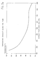
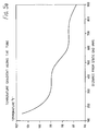
- a preform 1 in the form of a discrete length of tube of a suitable plastics material, for example polyethylene terepthalate (PET) and having a length of about a metre is heated in the hot air oven in such a manner as to differentially heat it along its length to create a temperature profile therealong, for example as illustrated in Figure 5a or 5b.
- the preform 1 is transferred from the oven 2 to the stretch/blow station 4 where it is retained by being secured by the grippers 13, 14 at respective ends of the preform (Figure 4a).
- the part of the preform lying between the grippers is denoted 98 throughout Figure 4.
- the mould halves of the mould 17 are heated to a temperature of about 180°C and close around the preform 1 and are locked in position.
- Heating can be accomplished by electrical resistance heating, heated oil, or a heated jacket or any other suitable method.
- the gripper head 14 is moved by a short distance (to the right in Figures 1 and 4) and applies a pretensioning force of 200N, for example, to the preform ( Figure 4b). This prevents the preform from sagging and prepares it for the ensuing stretch/blow process.
- the end of the preform secured by the gripper head 14 is sealed by a closure within the gripper head 14.
- Pressurised air is introduced into the other end of the preform via the hose 19 ( Figure 4c).
- Introduction of the pressurised air into the preform causes the static, higher temperature end of the central part 98 of the preform to begin to expand radially and simultaneously to undergo axial elongation, as manifest by an expansion front 100 (Figs. 4c to 4e).
- a work hardened front of expanded material develops in the polymer on this expansion front and moves with it.
- the axial elongation characteristics of the preform depend on the temperature profile achieved in the oven 4, and on the air pressure, and will be described in more detail hereinafter.
- the axial and hoop stretch induced by the pressurised air serves to orient the PET.
- the gripper head 14 is moved very quickly to the right ( Figure 4d) by the stretch rod mechanism 15, i.e. at a velocity at least in excess of 1ms ⁇ 1, and generally between 2 and 4 ms ⁇ 1.
- the stretch rod mechanism can be activated with introduction of the preblow air, or a short time thereafter to allow for initiation of the work hardened front.
- the delay can lie between 0.01 and 0.15 sec.
- the actual stretch rate depends on the process conditions, the material of the preform and the respective sizes of the preform and finished article.
- ⁇ 1 is the desired axial stretch ratio in the finished article.
- t preblow period
- L o is the initial length of the preform.
- the pressurised air is turned off just before stretching is completed and, after a preset delay, mainblow air at a higher pressure is introduced (Figure 4f).
- the high pressure air used to blow a component is thus achieved in two stages, identified as “preblow” which lies in the range from 60 psi to 135 psi (4 to 9 bar) and "mainblow” which lies in the range from 150 psi to 200 psi (10 to 14 bar) for straight walled articles and up to 600 psi (40 bar) for shaped articles. Close control of the preblow pressure, preferably to within 1 psi, is required to achieve a good blown component.
- the mainblow air achieves accurate conformity of the article with the mould.
- the mainblow air holds the article against the mould for a predetermined heat setting period, T, for example between 3 and 5 seconds.
- T a predetermined heat setting period
- the closure in the stretch gripper 14 is removed and water under pressure is introduced into the blown article via the water supply conduits 80 ( Figure 4g).
- the exhaust valve 94 is opened ( Figure 9d) to cause the water to be flushed along and out of the tube, via a conduit 102, with the pressurised air which is present in the article as a result of the mainblow stage.
- the flush valve causes the exhaust to be executed via the flow restrictor 98A.
- the direction of flushing is indicated by arrow A in Figure 4g.
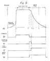
- FIG. 9a is a graph of the pressure in the article against time when the switching sequences for the main blow air, water spray, restricted exhaust and full exhaust shown in Figures 9b to 9d are adopted.
- the section o to t1 is the preblow/stretching stage where the article is expanded radially and axially.
- the high pressure mainblow air causes a marked increase in pressure which is maintained to time t2 to hold the article against the mould for the heat set time T.
- the water spray is commenced and the exhaust valve is opened.
- the pressure reduces slowly but in a manner such as to create turbulent movement of the water within the article.
- Substantially the entire internal surface area of the article between the grippers 13,14 is therefore wetted by the water and quickly loses heat to the water.
- the main exhaust commences and the pressure drops more quickly while turbulent cooling by the cooling water continues.
- the article becomes wholly rigid at a time about time t4, and the mould is opened around time t5.
- the water is introduced at a rate around 150cc per second through a nozzle of approximately 2.5mm in diameter.
- the precise flow rate can be tailored to suit requirements but should be sufficient to wet the inner surface of the article assisted by turbulence created by the departing gas.
- the heat energy which has been imparted to the tube from the oven 2 together with that generated during the stretching work undergone by the material contributes to raising the temperature of the tube to that required to achieve adequate thermal stability in the finished product. Also, of course, time is saved by avoiding the need to reheat at a subsequent stage in the process. Further, the blown component is already gripped and located within a mould, thus obviating the potentially difficult accurate handling of a large blown component into a subsequent machine.
Landscapes
- Physics & Mathematics (AREA)
- Thermal Sciences (AREA)
- Engineering & Computer Science (AREA)
- Manufacturing & Machinery (AREA)
- Mechanical Engineering (AREA)
- Blow-Moulding Or Thermoforming Of Plastics Or The Like (AREA)
- Moulds For Moulding Plastics Or The Like (AREA)
Description
- This invention relates to the manufacture of thermoplastic tubular articles, according to the preamble of
claim 1, particularly but not exclusively to the manufacture of tubular articles of saturated linear polyester material such as polyethylene terepthalate (PET), intended to form the bodies of processable food and beverage containers. - The invention also relates to an apparatus according to the preamble of
claim 7. - It is known in the manufacture of such articles that a high degree of orientation of the container body is desirable for improving its mechanical properties. This can be induced by mechanical deformation such as drawing, stretching or stretch-blow-moulding of the thermoplastic material.
- A method and apparatus for forming biaxially oriented tubular articles by stretch-blow-moulding are described in our British Publication No. 2089276A. In that method continuous hollow tube is drawn and blown to orient it, a can-sized length at a time and the oriented tube is chopped off. In contrast, the present invention is concerned with the manufacture of biaxially oriented articles from discrete lengths of plastic tube.
- It is known that an oriented article will shrink if heated to a temperature above that at which the orientation took place. Containers which are to be used for products which are filled when hot or thermally sterilised or pasteurised after filling must therefore be heat stabilised to an elevated temperature. This can be done by heating the oriented article to a temperature above the elevated temperature whilst restraining it from deformation: this process is known as "heat setting".
- Methods of heat setting suitable for open ended tubular oriented articles are known, for example as described in GB Patent publications 2172540 and 2179585. These publications are however concerned with the heat setting of an article after removal from the mould in which it has been oriented: thus in them it is necessary to transfer the article from the stretch-blow-moulding machine to a heat setting machine. Another difficulty is that the heat setting processes described there rely on positioning the oriented article on a mandrel and are therefore suited only to straight walled containers. They are not commercially applicable to shaped containers.
- European Publication No. 0081451 describes a process for producing heat set bottles (of length about 1/2m) where the orientation and heat treatment steps are carried out without the need for transferring the bottle to a separate station. This method is not applicable to a tubular article with two open ends. Further the method is carried out with the bottle held vertically and is not suitable for long articles.
- A further method and apparatus for stretch-blow moulding of tubular articles is disclosed in applicants' European Publication No 052490, upon which the preambles of the
independent claims - According to one aspect of the present invention there is provided a method of manufacturing from a hollow elongate preform of a crystallisable polymeric material an elongate thermoplastic tubular article which is open at both ends and which is dimensionally stable up to an elevated temperature, the method comprising:
- a) gripping end portions of the preform to define between the end portions a central portion from which the article is to be formed;
- b) introducing a pressurised gas into the preform to cause the central portion to expand radially against a mould heated to a temperature sufficient to cause heat setting, the central portion simultaneously undergoing elongation thereby to impart biaxial orientation to the finished article;
- c) maintaining the central portion in contact with the mould for a predetermined heat setting time with said pressurised gas held therein;
characterised by then: - d) rapidly cooling the central portion by simultaneously spraying cooling water into it and exhausting the said pressurised gas through one end of the preform, the exhaustion of gas not only creating turbulance by which the cooling water spray is caused to wet substantially the entire inner surface of the central portion but also purging the preform of a substantial quantity of the cooling water.
- The use of water as cooling liquid has many advantages, amongst which are that it is cheap and conveniently available and its latent heat of vapourisation can be used in the cooling process. It has hitherto not been considered appropriate to use water on its own as a cooling medium for heatsetting, but instead cryogenic substances such as low temperature gas mists have been proposed. However, in the present invention, by virtue of the turbulence and purging action created by the exhaustion of gas at high pressure heat may be quickly and efficiently removed from the polymer material of the central portion and carried out of the preform.
- It has been found that it is not essential for the purging of the cooling water by the gas to empty the cooling water from the article completely. Any water which does remain can be removed later after the article has been removed from the mould.
- The method defined above enables tubular articles to be manufactured even in excess of 2 metres, and is preferably carried out with such articles disposed horizontally. Further the method is suitable both for straight walled and shaped articles; for example, it may be used to produce shaped containers with adequate stability for receiving product at 95°C.
- In a preferred embodiment, the method includes, prior to step a), heating said preform to a temperature exceeding the glass transition temperature of the polymer material while providing a temperature gradient without discontinuities along the central portion. As will become apparent, the preferred embodiment is concerned with the stretch-blow-moulding of PET. For this material in its amorphous state the glass transition temperature (Tq) is typically 75°C, the temperature of its maximum rate of crystallisation after biaxial orientation being about 160°C. Preferably, the temperature of the preform prior to stretch-blow-moulding is between the ends of its central portion being about 5°C.
- The inventors have discovered that by providing a controlled temperature differential between the ends of the central portion and by controlling the air pressure (in dependence on the polymer), long (>2m) articles of a very uniform wall thickness and with consistent material qualities can be produced repeatably. This is discussed in more detail in our copending application No. 90313444.3 (Published No 0434277) filed today, the contents of which are herein incorporated by reference. The present invention enables such long articles to be formed and heat set quickly and in an energy efficient manner.
- The thermoplastics materials which are preferred for use in the method of the present invention are crystallisable polymers with well-defined natural stretch ratios. The preferred material is a polyester homopolymer, which consists of polymer units derived from ethylene terephthalate, produced from terephthalic acid plus ethylene glycol (PET). Other suitable materials include polyester copolymers which consist of polymer units based on ethylene terephthalate, produced from terephthalic acid, isophthalic acid, plus ethylene glycol, diethylene glycol, cyclohexane dimethanol but could also include other polyesters or copolyesters including poly (ethylene isophthalate) PEI, poly (ethylene napthalene-dicarboxylate) PEN., or polyester or copolyester blends.
- The method is also suitable for multilayer preforms, for example coextruded structures of PET with a gas barrier material such as an ethylene vinyl alcohol copolymer or a polyamide copolymer.
- According to another aspect of the present invention, there is provided apparatus for manufacturing from a hollow preform of a crystallisable polymeric material an elongate thermoplastic tubular article which is open at both ends and which is dimensionally stable up to an elevated temperature, the apparatus comprising:
- a) first and second spaced gripping means for gripping respective end portions of the preform so as to define a central portion of the preform from which the article is to be formed;
- b) a heated elongate mould to surround the central portion when the preform is held by the gripping means;
- c) means including a conduit in the first gripping means for introducing pressurised gas into the preform to cause it to expand radially against the mould, the preform simultaneously undergoing elongation thereby to impart biaxial orientation to the finished article, and to maintain the article in contact with the mould for a predetermined heat setting time;
characterised by: - d) spray means including water supply conduits in the gripping means for spraying cooling water into the article after the said heat setting time; and
- e) exhaust means including an exhaust conduit in the second gripping means openable simultaneously with the spray means for exhausting the pressurised gas through one end of the preform, such exhaustion of gas not only creating turbulence by which the cooling water spray is caused to wet substantially the entire inner surface of the central portion but also purging the preform of a substantial quantity of the water.
- Preferably the apparatus also includes a heating device for preheating said preform to a temperature above the glass transition temperature while providing a temperature gradient without discontinuities between the ends of the preform, one end being at a temperature at least 3° lower than that of the other end.
- Preferably the support means comprises first and second grippers for gripping respective ends of the preform, the second gripper being movable relative to the first to stretch the preform.
- For a better understanding of the present invention and to show how the same may be carried into effect reference will now be made by way of example to the accompanying drawings, in which:-
- Figure 1 is a block diagram of apparatus for manufacturing thermoplastic articles;
- Figure 2 is a diagram showing air and water supplies to the apparatus;
- Figure 3 is a cross section through a part of the apparatus showing air and water supply ducts;
- Figures 4(a) to 4(g) are diagrams illustrating steps in the manufacturing process;
- Figures 5(a) and 5(b) are graphs showing exemplary temperature profiles applied to the preforms;
- Figure 6 is a graph showing the height reduction of heat set containers vs. heat set temperature;
- Figure 7 is a graph of the diameter reduction of heat set containers vs. heat set temperature;
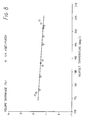
- Figure 8 is a graph of the volume shrinkage of heat set articles vs. heat set temperature;
- Figure 9 is a timing chart for a preferred embodiment of the method of the present invention; and
- Figure 10 is a graph comparing the crystallinity of heat set and non-heat set articles.
- The apparatus comprises a
hot air oven 2 mounted above a stretch/blow station 4. Theoven 2 has associated therewith atube supply device 10 which sequentially supplies preforms in the form of elongate tubes to preformtrays 6 of acarrier 8. The preforms are hollow extruded tubes made of PET or another suitable polymer and having a length of about 1m. Thecarrier 8 has a plurality of vertically spaced preform trays. Thecarrier 8 moves stepwise to carry preforms vertically downwards through thehot air oven 2 wherein they are heated. Anair heater 7 heats the air for the oven whilethermocouples tube transfer device 12 transfers the tube from the oven to the stretch/blow station 4 where it is supported by a "static"gripper 13 at one end of themould 17 and a "stretch"gripper 14 carried from the axially opposite end of themould 17. The corresponding ends of the preform are termed the "static" end and the "stretch" end. Thestatic gripper 13 is so-called because apart from moving a short distance back and forth to collect and grip an incoming tube it remains substantially in the same position. Thestatic gripper 13 has a hollow gripper head permitting the supply of air and water from anair supply hose 19 andwater supply conduit 80. The heads of thegrippers mould 17 comprises two halves, one of which can be seen in Figure 1, which are locked together once the preform is in place. - The
stretch gripper 14 can be moved axially to the right in Figure 1 under the control of adrive unit 16 movable on atrack 22 driven by anylon belt 24 which in turn is driven by aservomotor 15. Theservomotor 15 is controlled by a dedicated motion controller (not shown) to move astretch rod 20 attached to thestretch gripper 14 to a preset position at a preset velocity once blowing has commenced. The dedicated motion controller is preprogrammed with operational conditions depending on the requirements of the stretch/blow process and the specification of the product. Finally, atransfer device 18 is operable to remove the blown container from themould 17. - Figure 2 shows the air and water supplies to the stretch/
blow station 4.Respective valves static gripper 13 via theair supply hose 19. Water is supplied from areservoir 84 by means of apump 86 torespective spray guns respective pilot valves spray guns article 1 via respectivewater supply conduits 80. Avalve arrangement 92 controls release of the air/water flushing mixture from the article. Thevalve arrangement 92 comprises anexhaust valve 94, aflush valve 96 and a flow restrictor 98A. Figure 3 shows the air and water supplies to thestatic gripper 13 in more detail. Thewater supply conduit 80 comprises small bore copper piping held centrally of theair supply conduit 19 byfins 94. The arrangement at thestretch gripper 14 is similar. A suitable nozzle is used to spray the water into the article. - Reference will now be made to Figures 4a to 4g to describe a method of manufacturing thermoplastics articles which are biaxially oriented and heat set. Although the method will be described in relation to a single preform, it will be apparent that the apparatus is capable of operating with a continuous supply of preforms. That is, the
tube supply device 10 sequentially supplies preforms torespective preform trays 6 of thecarrier 8. Thesepreform trays 6 are indexed through theoven 2, in time to ensure that a preform exiting from the oven has the correct temperature profile. As an example, the dwell time of a preform in theoven 2 might be about four minutes. The dwell time is controlled by the indexing speed of thecarrier 8. Thepreform trays 6 support the preforms over their entire length. Indexing of the carrier is controlled by a machine controller (not shown) in response to the mechanical and pneumatic movement in the stretch/blow station, as discussed hereinbelow. - A
preform 1 in the form of a discrete length of tube of a suitable plastics material, for example polyethylene terepthalate (PET) and having a length of about a metre is heated in the hot air oven in such a manner as to differentially heat it along its length to create a temperature profile therealong, for example as illustrated in Figure 5a or 5b. Thepreform 1 is transferred from theoven 2 to the stretch/blow station 4 where it is retained by being secured by thegrippers mould 17 are heated to a temperature of about 180°C and close around thepreform 1 and are locked in position. Heating can be accomplished by electrical resistance heating, heated oil, or a heated jacket or any other suitable method. Thegripper head 14 is moved by a short distance (to the right in Figures 1 and 4) and applies a pretensioning force of 200N, for example, to the preform (Figure 4b). This prevents the preform from sagging and prepares it for the ensuing stretch/blow process. - The end of the preform secured by the
gripper head 14 is sealed by a closure within thegripper head 14. Pressurised air is introduced into the other end of the preform via the hose 19 (Figure 4c). Introduction of the pressurised air into the preform causes the static, higher temperature end of thecentral part 98 of the preform to begin to expand radially and simultaneously to undergo axial elongation, as manifest by an expansion front 100 (Figs. 4c to 4e). A work hardened front of expanded material develops in the polymer on this expansion front and moves with it. The axial elongation characteristics of the preform depend on the temperature profile achieved in theoven 4, and on the air pressure, and will be described in more detail hereinafter. The axial and hoop stretch induced by the pressurised air serves to orient the PET. To aid the axial elongation thegripper head 14 is moved very quickly to the right (Figure 4d) by thestretch rod mechanism 15, i.e. at a velocity at least in excess of 1ms⁻¹, and generally between 2 and 4 ms⁻¹. The stretch rod mechanism can be activated with introduction of the preblow air, or a short time thereafter to allow for initiation of the work hardened front. The delay can lie between 0.01 and 0.15 sec. The actual stretch rate depends on the process conditions, the material of the preform and the respective sizes of the preform and finished article. - The relationship between the stretch rate, the stretch ratio and the preblow period is given by the following equation:

λ₁ is the desired axial stretch ratio in the finished article.
Δ =
t = preblow period
Lo is the initial length of the preform. - (1) An example using typical values for these parameters is given below:

The expansion front and work hardened front move progressively along the preform until they reach the lower temperature, stretch end of thecentral part 98. - The pressurised air is turned off just before stretching is completed and, after a preset delay, mainblow air at a higher pressure is introduced (Figure 4f). The high pressure air used to blow a component is thus achieved in two stages, identified as "preblow" which lies in the range from 60 psi to 135 psi (4 to 9 bar) and "mainblow" which lies in the range from 150 psi to 200 psi (10 to 14 bar) for straight walled articles and up to 600 psi (40 bar) for shaped articles. Close control of the preblow pressure, preferably to within 1 psi, is required to achieve a good blown component. The mainblow air achieves accurate conformity of the article with the mould.
- Referring to Figures 9a and 9b, the mainblow air holds the article against the mould for a predetermined heat setting period, T, for example between 3 and 5 seconds. The closure in the
stretch gripper 14 is removed and water under pressure is introduced into the blown article via the water supply conduits 80 (Figure 4g). Theexhaust valve 94 is opened (Figure 9d) to cause the water to be flushed along and out of the tube, via aconduit 102, with the pressurised air which is present in the article as a result of the mainblow stage. Initially, the flush valve causes the exhaust to be executed via the flow restrictor 98A. The direction of flushing is indicated by arrow A in Figure 4g. As soon as the quenching operation has chilled the blown article sufficiently to impart rigidity, after about 1 to 3 seconds, the flush valve is switched to full exhaust, i.e. no longer via the flow restrictor. When the air pressure has reduced sufficiently, the hot mould is opened. The blown article is still prone to shrinkage whilst exposed to the radiant heat from the mould, and so flushing with the water/air mixture should continue until the mould is fully opened (Figure 9e). After flushing, the blown component is transferred from the stretch/blow machine. If it contains a residue of water, a subsequent draining and drying process is necessary. Figure 9a is a graph of the pressure in the article against time when the switching sequences for the main blow air, water spray, restricted exhaust and full exhaust shown in Figures 9b to 9d are adopted. - In Figure 9a, the section o to t₁ is the preblow/stretching stage where the article is expanded radially and axially. At time t₁, the high pressure mainblow air causes a marked increase in pressure which is maintained to time t₂ to hold the article against the mould for the heat set time T. At time t₂, the water spray is commenced and the exhaust valve is opened. The pressure reduces slowly but in a manner such as to create turbulent movement of the water within the article. Substantially the entire internal surface area of the article between the
grippers - The water is introduced at a rate around 150cc per second through a nozzle of approximately 2.5mm in diameter. The precise flow rate can be tailored to suit requirements but should be sufficient to wet the inner surface of the article assisted by turbulence created by the departing gas.
- The heat energy which has been imparted to the tube from the
oven 2 together with that generated during the stretching work undergone by the material contributes to raising the temperature of the tube to that required to achieve adequate thermal stability in the finished product. Also, of course, time is saved by avoiding the need to reheat at a subsequent stage in the process. Further, the blown component is already gripped and located within a mould, thus obviating the potentially difficult accurate handling of a large blown component into a subsequent machine. - Examples of the characteristics of heat set products produced by the described process are shown in Figures 6 to 8 and 10. From these Figures, the consistent qualities of articles produced by the above described method can be seen.
Claims (8)
- A method of manufacturing from a hollow elongate preform (1) of a crystallisable polymeric material an elongate thermoplastic tubular article which is open at both ends and which is dimensionally stable up to an elevated temperature, the method comprising:a) gripping end portions of the preform to define between the end portions a central portion from which the article is to be formed;b) introducing a pressurised gas into the preform to cause the central portion to expand radially against a mould (17) heated to a temperature sufficient to cause heat setting, the central portion simultaneously undergoing elongation thereby to impart biaxial orientation to the finished article;c) maintaining the central portion in contact with the mould for a predetermined heat setting time with said pressurized gas held therein; characterised by then,d) rapidly cooling the central portion by simultaneously spraying cooling water into it and exhausting the said pressurised gas through one end of the preform, the exhaustion of gas not only creating turbulance by which the cooling water spray is caused to wet substantially the entire inner surface of the central portion but also purging the preform of a substantial quantity of the cooling water.
- A method as claimed in claim 1 or 2 for a preform of PET, wherein the mould (17) is heated to a temperature in the range 120°C to 240°C for heat setting.
- A method as claimed in claim 1 or claim 2, wherein a first part of the exhaustion of gas is carried out through a flow restrictor (98A).
- A method as claimed in any preceding claim for a preform of PET, wherein the gas pressure at the beginning of step (d) exceeds 10 bars.
- A method as claimed in claim 4, wherein the gas pressure at the beginning of step (d) is within the range 10 to 14 bars.
- A method as claimed in any preceding claim comprising, prior to step (a), heating said preform to a temperature exceeding the glass transition temperature of the polymer material while providing a temperature gradient without discontinuities along the central portion.
- Apparatus for manufacturing from a hollow preform of a crystallisable polymeric material an elongate thermoplastic tubular article which is open at both ends and which is dimensionally stable up to an elevated temperature, the apparatus comprising:a) first and second spaced gripping means (13, 14) for gripping respective end portions of the preform so as to define a central portion (98) of the preform from which the article is to be formed;b) a heated elongate mould (17) to surround the central portion when the preform is held by the gripping means;c) means including a conduit in the first gripping means (82, 83, 19, 13) for introducing pressurised gas into the preform to cause it to expand radially against the mould, the preform simultaneously undergoing elongation thereby to impart biaxial orientation to the finished article, and to maintain the article in contact with the mould for a predetermined heating setting time;
characterised by:d) spray means (80) including water supply conduits in the gripping means for spraying cooling water into the article after the said heat setting time; ande) exhaust means (14, 92, 94, 96, 98A) including an exhaust conduit (102) in the second gripping means openable simultaneously with the spray means for exhausting the pressurised gas through one end of the preform, such exhaustion of gas not only creating turbulence by which the cooling water spray is caused to wet substantially the entire inner surface of the central portion but also purging the preform of a substantial quantity of the water. - Apparatus as claimed in claim 7, wherein the first gripping means (13) is static and the second gripping means (14) is movable away from the first gripping means longitudinally of the preform during the said elongation of the preform.
Applications Claiming Priority (2)
| Application Number | Priority Date | Filing Date | Title |
|---|---|---|---|
| GB8928350A GB2238975A (en) | 1989-12-15 | 1989-12-15 | Heatsetting of thermoplastics tubular articles |
| GB8928350 | 1989-12-15 |
Publications (2)
| Publication Number | Publication Date |
|---|---|
| EP0434276A1 EP0434276A1 (en) | 1991-06-26 |
| EP0434276B1 true EP0434276B1 (en) | 1995-02-15 |
Family
ID=10667987
Family Applications (1)
| Application Number | Title | Priority Date | Filing Date |
|---|---|---|---|
| EP90313443A Expired - Lifetime EP0434276B1 (en) | 1989-12-15 | 1990-12-11 | Heatsetting of thermoplastic tubular articles |
Country Status (4)
| Country | Link |
|---|---|
| EP (1) | EP0434276B1 (en) |
| JP (1) | JPH04261824A (en) |
| DE (1) | DE69016973T2 (en) |
| GB (1) | GB2238975A (en) |
Families Citing this family (4)
| Publication number | Priority date | Publication date | Assignee | Title |
|---|---|---|---|---|
| DE4300597A1 (en) * | 1993-01-13 | 1994-07-14 | Basf Ag | Process for the production of hollow bodies from thermoplastic materials |
| WO2002072334A2 (en) * | 2001-03-13 | 2002-09-19 | 'fasti' Farrag & Stipsits Gmbh | Method for producing plastic molded parts using a blowing mold and an injection lance |
| JP4698450B2 (en) * | 2006-03-15 | 2011-06-08 | 株式会社オプコ | Blow molding apparatus and blow molding method |
| EP2123424B1 (en) * | 2007-01-18 | 2019-09-18 | Molecor Tecnología S.l. | Equipment for producing molecularly bioriented tubular profiles and corresponding method |
Family Cites Families (7)
| Publication number | Priority date | Publication date | Assignee | Title |
|---|---|---|---|---|
| US3505442A (en) * | 1967-08-22 | 1970-04-07 | Phillips Petroleum Co | Method for cooling blow molded articles |
| FR2389478B1 (en) * | 1977-05-04 | 1980-11-28 | Rhone Poulenc Ind | |
| FR2484324A1 (en) * | 1980-06-13 | 1981-12-18 | Rhone Poulenc Ind | PROCESS FOR THE PRODUCTION OF RIGID TUBULAR PROFILES WITH THIN WALLS |
| GB2089276B (en) * | 1980-11-19 | 1984-09-05 | Metal Box Co Ltd | Thermoplastics tubular articles |
| GB2145027B (en) * | 1983-08-19 | 1986-10-08 | Metal Box Plc | Tubular articles of biaxially oriented polymers |
| GB2172540B (en) * | 1985-03-18 | 1988-12-21 | Metal Box Plc | Making dimensionally stable thermoplastic open-ended tubular articles |
| CA1288913C (en) * | 1986-09-22 | 1991-09-17 | Prakash R. Ajmera | Method and apparatus for making a partially crystalline, biaxially oriented heat set hollow plastic container |
-
1989
- 1989-12-15 GB GB8928350A patent/GB2238975A/en not_active Withdrawn
-
1990
- 1990-12-11 DE DE69016973T patent/DE69016973T2/en not_active Expired - Fee Related
- 1990-12-11 EP EP90313443A patent/EP0434276B1/en not_active Expired - Lifetime
- 1990-12-14 JP JP2402449A patent/JPH04261824A/en active Pending
Also Published As
| Publication number | Publication date |
|---|---|
| GB2238975A (en) | 1991-06-19 |
| JPH04261824A (en) | 1992-09-17 |
| DE69016973D1 (en) | 1995-03-23 |
| GB8928350D0 (en) | 1990-02-21 |
| DE69016973T2 (en) | 1995-07-20 |
| EP0434276A1 (en) | 1991-06-26 |
Similar Documents
| Publication | Publication Date | Title |
|---|---|---|
| EP1212187B1 (en) | Blow molding method and machine for producing pasteurizable containers | |
| EP1232055B1 (en) | Blow molding method and machine for producing pasteurizable containers | |
| EP1305152B1 (en) | Method for producing plastic containers having high crystallinity bases | |
| US4039641A (en) | Plastics container manufacture | |
| EP0746457B1 (en) | Blow mold annealing and heat treating articles | |
| EP0596487B1 (en) | Process for heat treating thermoplastic containers | |
| US5560943A (en) | Apparatus for annealing and blowing a thermoplastic biaxially oriented container | |
| NL8400683A (en) | HOLDER. | |
| GB2138735A (en) | A method and apparatus for forming hollow bodies from hot-workable plastics material | |
| JPH0214886B2 (en) | ||
| AU569316B2 (en) | Tubular articles of biaxially oriented polymers | |
| EP0434276A1 (en) | Heatsetting of thermoplastic tubular articles | |
| EP0228106B1 (en) | Method for moulding hollow containers in molecularly orientatable plastics material | |
| US5378421A (en) | Process for preparing thermoplastic containers | |
| JPH0546300B2 (en) | ||
| EP0434277B1 (en) | Manufacture of thermoplastic tubular articles | |
| EP0768166B1 (en) | Single-stage apparatus and method for producing containers made of thermoplastic material | |
| JPH085125B2 (en) | Biaxial stretch blow molding method | |
| JP3014876B2 (en) | Heat resistant container molding equipment | |
| AU738056B2 (en) | Single-stage apparatus and method for producing containers made of thermoplastic material | |
| JPH0541421B2 (en) | ||
| JPS58208022A (en) | Blowing molding device and its method |
Legal Events
| Date | Code | Title | Description |
|---|---|---|---|
| PUAI | Public reference made under article 153(3) epc to a published international application that has entered the european phase |
Free format text: ORIGINAL CODE: 0009012 |
|
| 17P | Request for examination filed |
Effective date: 19901220 |
|
| AK | Designated contracting states |
Kind code of ref document: A1 Designated state(s): DE FR GB NL |
|
| 17Q | First examination report despatched |
Effective date: 19931209 |
|
| RAP1 | Party data changed (applicant data changed or rights of an application transferred) |
Owner name: CARNAUDMETALBOX PLC |
|
| GRAA | (expected) grant |
Free format text: ORIGINAL CODE: 0009210 |
|
| AK | Designated contracting states |
Kind code of ref document: B1 Designated state(s): DE FR GB NL |
|
| PG25 | Lapsed in a contracting state [announced via postgrant information from national office to epo] |
Ref country code: NL Effective date: 19950215 |
|
| REF | Corresponds to: |
Ref document number: 69016973 Country of ref document: DE Date of ref document: 19950323 |
|
| ET | Fr: translation filed | ||
| NLV1 | Nl: lapsed or annulled due to failure to fulfill the requirements of art. 29p and 29m of the patents act | ||
| RAP2 | Party data changed (patent owner data changed or rights of a patent transferred) |
Owner name: CARNAUDMETALBOX PLC |
|
| PG25 | Lapsed in a contracting state [announced via postgrant information from national office to epo] |
Ref country code: GB Effective date: 19951211 |
|
| PLBE | No opposition filed within time limit |
Free format text: ORIGINAL CODE: 0009261 |
|
| STAA | Information on the status of an ep patent application or granted ep patent |
Free format text: STATUS: NO OPPOSITION FILED WITHIN TIME LIMIT |
|
| 26N | No opposition filed | ||
| GBPC | Gb: european patent ceased through non-payment of renewal fee |
Effective date: 19951211 |
|
| PG25 | Lapsed in a contracting state [announced via postgrant information from national office to epo] |
Ref country code: FR Effective date: 19960830 |
|
| PG25 | Lapsed in a contracting state [announced via postgrant information from national office to epo] |
Ref country code: DE Effective date: 19960903 |
|
| REG | Reference to a national code |
Ref country code: FR Ref legal event code: ST |