EP0433962B1 - Steel cord for reinforcement of rubber products - Google Patents
Steel cord for reinforcement of rubber products Download PDFInfo
- Publication number
- EP0433962B1 EP0433962B1 EP90124527A EP90124527A EP0433962B1 EP 0433962 B1 EP0433962 B1 EP 0433962B1 EP 90124527 A EP90124527 A EP 90124527A EP 90124527 A EP90124527 A EP 90124527A EP 0433962 B1 EP0433962 B1 EP 0433962B1
- Authority
- EP
- European Patent Office
- Prior art keywords
- steel cord
- wires
- cord
- rubber
- diameter
- Prior art date
- Legal status (The legal status is an assumption and is not a legal conclusion. Google has not performed a legal analysis and makes no representation as to the accuracy of the status listed.)
- Expired - Lifetime
Links
Images


Classifications
-
- D—TEXTILES; PAPER
- D07—ROPES; CABLES OTHER THAN ELECTRIC
- D07B—ROPES OR CABLES IN GENERAL
- D07B1/00—Constructional features of ropes or cables
- D07B1/06—Ropes or cables built-up from metal wires, e.g. of section wires around a hemp core
- D07B1/0606—Reinforcing cords for rubber or plastic articles
- D07B1/0646—Reinforcing cords for rubber or plastic articles comprising longitudinally preformed wires
-
- B—PERFORMING OPERATIONS; TRANSPORTING
- B60—VEHICLES IN GENERAL
- B60C—VEHICLE TYRES; TYRE INFLATION; TYRE CHANGING; CONNECTING VALVES TO INFLATABLE ELASTIC BODIES IN GENERAL; DEVICES OR ARRANGEMENTS RELATED TO TYRES
- B60C9/00—Reinforcements or ply arrangement of pneumatic tyres
- B60C9/0007—Reinforcements made of metallic elements, e.g. cords, yarns, filaments or fibres made from metal
-
- B—PERFORMING OPERATIONS; TRANSPORTING
- B60—VEHICLES IN GENERAL
- B60C—VEHICLE TYRES; TYRE INFLATION; TYRE CHANGING; CONNECTING VALVES TO INFLATABLE ELASTIC BODIES IN GENERAL; DEVICES OR ARRANGEMENTS RELATED TO TYRES
- B60C9/00—Reinforcements or ply arrangement of pneumatic tyres
- B60C9/0057—Reinforcements comprising preshaped elements, e.g. undulated or zig-zag filaments
-
- D—TEXTILES; PAPER
- D07—ROPES; CABLES OTHER THAN ELECTRIC
- D07B—ROPES OR CABLES IN GENERAL
- D07B2201/00—Ropes or cables
- D07B2201/20—Rope or cable components
- D07B2201/2001—Wires or filaments
- D07B2201/2007—Wires or filaments characterised by their longitudinal shape
-
- D—TEXTILES; PAPER
- D07—ROPES; CABLES OTHER THAN ELECTRIC
- D07B—ROPES OR CABLES IN GENERAL
- D07B2201/00—Ropes or cables
- D07B2201/20—Rope or cable components
- D07B2201/2001—Wires or filaments
- D07B2201/2007—Wires or filaments characterised by their longitudinal shape
- D07B2201/2008—Wires or filaments characterised by their longitudinal shape wavy or undulated
-
- D—TEXTILES; PAPER
- D07—ROPES; CABLES OTHER THAN ELECTRIC
- D07B—ROPES OR CABLES IN GENERAL
- D07B2201/00—Ropes or cables
- D07B2201/20—Rope or cable components
- D07B2201/2015—Strands
- D07B2201/2022—Strands coreless
-
- D—TEXTILES; PAPER
- D07—ROPES; CABLES OTHER THAN ELECTRIC
- D07B—ROPES OR CABLES IN GENERAL
- D07B2201/00—Ropes or cables
- D07B2201/20—Rope or cable components
- D07B2201/2015—Strands
- D07B2201/2024—Strands twisted
-
- D—TEXTILES; PAPER
- D07—ROPES; CABLES OTHER THAN ELECTRIC
- D07B—ROPES OR CABLES IN GENERAL
- D07B2201/00—Ropes or cables
- D07B2201/20—Rope or cable components
- D07B2201/2015—Strands
- D07B2201/2038—Strands characterised by the number of wires or filaments
-
- D—TEXTILES; PAPER
- D07—ROPES; CABLES OTHER THAN ELECTRIC
- D07B—ROPES OR CABLES IN GENERAL
- D07B2205/00—Rope or cable materials
- D07B2205/30—Inorganic materials
- D07B2205/3021—Metals
- D07B2205/3025—Steel
- D07B2205/3046—Steel characterised by the carbon content
- D07B2205/3053—Steel characterised by the carbon content having a medium carbon content, e.g. greater than 0,5 percent and lower than 0.8 percent respectively HT wires
-
- D—TEXTILES; PAPER
- D07—ROPES; CABLES OTHER THAN ELECTRIC
- D07B—ROPES OR CABLES IN GENERAL
- D07B2205/00—Rope or cable materials
- D07B2205/30—Inorganic materials
- D07B2205/3021—Metals
- D07B2205/3025—Steel
- D07B2205/3046—Steel characterised by the carbon content
- D07B2205/3057—Steel characterised by the carbon content having a high carbon content, e.g. greater than 0,8 percent respectively SHT or UHT wires
-
- D—TEXTILES; PAPER
- D07—ROPES; CABLES OTHER THAN ELECTRIC
- D07B—ROPES OR CABLES IN GENERAL
- D07B2501/00—Application field
- D07B2501/20—Application field related to ropes or cables
- D07B2501/2046—Tyre cords
-
- D—TEXTILES; PAPER
- D07—ROPES; CABLES OTHER THAN ELECTRIC
- D07B—ROPES OR CABLES IN GENERAL
- D07B2501/00—Application field
- D07B2501/20—Application field related to ropes or cables
- D07B2501/2076—Power transmissions
-
- Y—GENERAL TAGGING OF NEW TECHNOLOGICAL DEVELOPMENTS; GENERAL TAGGING OF CROSS-SECTIONAL TECHNOLOGIES SPANNING OVER SEVERAL SECTIONS OF THE IPC; TECHNICAL SUBJECTS COVERED BY FORMER USPC CROSS-REFERENCE ART COLLECTIONS [XRACs] AND DIGESTS
- Y10—TECHNICAL SUBJECTS COVERED BY FORMER USPC
- Y10S—TECHNICAL SUBJECTS COVERED BY FORMER USPC CROSS-REFERENCE ART COLLECTIONS [XRACs] AND DIGESTS
- Y10S57/00—Textiles: spinning, twisting, and twining
- Y10S57/902—Reinforcing or tyre cords
Definitions
- This invention relates to a steel cord for reinforcement of rubber products of a novel twisting structure to be used for reinforcement of rubber products such as automobile tires, conveyor belts, etc.
- a steel cord used for reinforcement of rubber products such as tires, etc. is composed by intertwisting 3, 4 or 5 pieces of metal wires into a strand (1x3, 1x4 or 1x5 construction).
- an "open-type" construction is realized by intertwisting the wire after preforming them in a way to have a gap between the wire to allow the rubber to penetrate into the cord.
- US-A-4 836 262 discloses an open-type steel cord of 1x3 construction made of a high carbon steel wire of 0,75 - 0,85 % carbon having a wire diameter of less than 0,40 mm. Said wires are twisted together at a twist pitch of 6,5 - 20 mm to improve the penetrability of the coating rubber into the cord.
- JP-A-59 156 805 shows an open-twisted steel cord of 1x5 construction having an oval (elleptical) cross section with a rate of maximum/minimum diameter established at 1,1 - 2,3. The orientation of the oval shape changes alternately in the direction of the cord.
- a steel cord of 1x2 construction was still poor in fatigue resistance and flexibility, because the metal wires which are in contact with each other are liable to produce fretting wear and no rubber compound penetrates into the portion of wire contacts forming a wire construction which seems as if it were made by twisting flat wires, leading to easy occurrence of buckling against repetitive compressions and tensile & bending fatigues.
- the said steel cord was also unsatisfactory in the matter of corrosion resistance because the material wires which are in contact with each other cannot be covered completely with the rubber.
- the present invention has been made for the purpose of providing a steel cord for reinforcement of rubber products with improved fatigue resistance, flexibility and corrosion resistance and has the characteristics as described hereunder.
- the steel cord of the present invention is composed by
- the steel cord of the present invention ensures good penetration of the rubber between the material wires. And yet, it has a sufficient strength of steel cord and a stable twisting.
- this steel cord in the case where this steel cord is used for rubber products such as tires, etc., it provides improved corrosion resistance, fatigue resistance and flexibility without sacrificing the ease of handling. Moreover, when this steel cord is used for tires, it can remarkably extend the service life of the tire and also improves the driving comfort.
- Fig. 1a is a schematic plan view indicating an example of the steel cord according to the present invention.
- I to VII of Fig. 1b are cross-sectional views at lines I - I to VII - VII of Fig. 1a.
- Fig. 2a is a schematic plan view indicating an example of the steel cord according to the present invention having a cross section of elliptical shape.
- Fig. 2b is a front view of the above.
- I to VII of Fig. 2c are cross-sectional views at lines I - I to VII - VII of Fig. 2a.
- Fig. 3a is a cross-sectional view of a steel cord having a gap between the material wires.
- Fig. 1a is a schematic plan view indicating an example of the steel cord according to the present invention.
- I to VII of Fig. 1b are cross-sectional views at lines I - I to VII - VII of Fig. 1a.
- Fig. 2a is a schematic plan
- FIG. 3b is a cross-sectional view of a densely twisted steel cord.
- Fig. 4a is a schematic plan view indicating an example of the steel cord according to the present invention.
- I to VII of Fig. 4b are cross-sectional views at lines I - I to VII - VII of Fig. 4a.
- Fig. 5 is a cross-sectional view of a complex sheet provided with a buried steel cord.
- Fig. 6 is a partial enlarged cross-sectional view of a tire using a complex sheet for the belt.
- the steel cord (2) according to the present invention is composed by twisting material wires (1), (1) of a diameter of 0.25 to 0.40 mm and a carbon content of 0.75 to 0.88 wt % at a twist pitch of 9.0 to 16.0 mm and an average of preforming rate of 105 to 150% as shown in Fig. 1.
- the said steel cord can also form a steel cord (2) having sections of nearly elliptical shape in about the same direction in the longitudinal direction and their ratio of length D 1 to breadth D 2 is 1.1 ⁇ D 1 /D 2 ⁇ 2.2, by being passed through a straightener in which flat rollers of a small diameter are arranged in zigzag as shown in Fig. 2.
- the value of do in the case where the shape of the section is elliptical is also a mean value of measured values at a plural number of points in the longitudinal direction.
- the steel cord (2) of the above example can maintain the strength and the flexibility required of steel cord because the diameter, the carbon content and the twist pitch of the material wires are restricted as mentioned above. In addition, it can also ensure good penetration of a rubber compound between the material wires by providing a gap between the material wires (1) as shown in Fig. 1 and Fig. 2 because its average of preforming rate is set at 105 to 150%. And the corrosion resistance of the steel cord further improves and hardly any fretting wear due to friction of materials wires is produced because the material wires are entirely covered with the rubber compound. Yet, the respective material wires also play the role of reinforcement for rubber individually while serving as steel cord, thus preventing occurrence of buckling and improving the fatigue resistance and the flexibility of the steel cord.
- the above-mentioned wave pitch means M as indicated in Fig. 4a and its value against the twist pitch C is found within the range of M 0.1C to 0.7C.
- Wavy outside diameter N means the apparent outside diameter of a waved material wire as shown in Fig. 4b.
- Wavy spiral means about spiral forms made by intertwisting two material wires which may not necessarily be exactly spiral but may be just wavy if only they produce the same effect as that of a spiral.
- this type of steel cord is stable in twist structure and very easy for handling because the material wires are repeating contact and separation at proper intervals, thus preventing occurrence of buckling and improving the fatigue resistance and the flexibility of the steel cord.
- the reason why the diameter of each material wire was decided as no less than 0.25 mm ⁇ and no more than 0.40 mm ⁇ is that, when the steel cord is used for tires, etc., 0.25 mm ⁇ is the minimum requirement for obtaining a proper strength considering the smaller number of materials wires compared with conventional ones but a steel cord in excess of 0.40 mm ⁇ lacks in flexibility.
- carbon content at least 0.75% is required to use a high tensile strength wire but a carbon content in excess of 0.88% leads to frequent breakings of wire in the drawing and twisting processes.
- twist pitch must be kept at no more than 16.00 mm.
- the twist pitch is under 9.0 mm, the steel cord becomes unfit for reinforcement of tires, etc. because of an excessively large elongation.
- the average of preforming rate should preferably be 105 to 150%, and the ideal ratio is 130 to 145%.
- the wave pitch is smaller than 0.1 times the twist pitch, the elongation at the time of a low-load traction gets larger, making it difficult to maintain the dimension at the time of forming.
- the wave pitch is larger than 0.7 times the twist pitch, the twisting becomes proper and the steel cord deteriorates in in fatigue resistance and handling workability.
- the wavy outside diameter is smaller than (A + 2/100) mm, the penetration of rubber becomes insufficient, but if it is larger than (A + 2/10) mm the maintenance of dimensions at the time of forming becomes difficult because of an easy elongation of the wire and it also leads to poor workability in the calendering of rubber sheet.
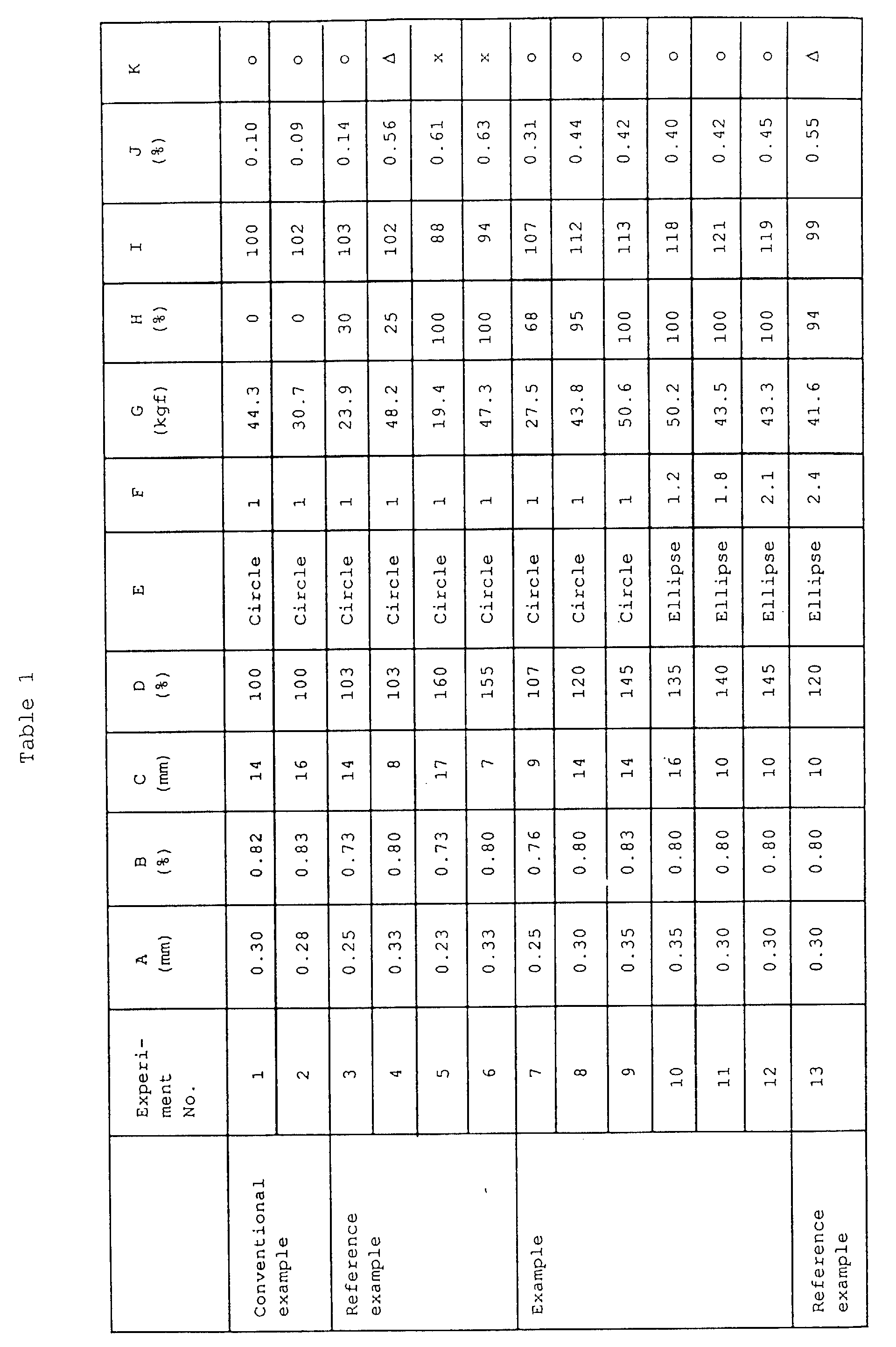
- Table 1 indicates the results of tests of various kinds of steel cord made by intertwisting two material wires provided with brass plating on the surface, with variations in material wire diameter, carbon content, twist pitch, average of preforming rate and shape of section of the steel cord.
- Experiments No. 1 & 2 represent the conventional steel cord indicated in the said official gazette No. PDS-62-234921 and No. PDS-62-117893 as shown in Fig. 8.
- Experiments No. 7 - 9 indicate the steel cord (2) according to the invention of the present application with a nearly round section shape which is the example indicated in Fig. 1.
- Experiments No. 10 - 12 show the steel cord (2) according to the invention of the present application with a nearly elliptical section shape which is the example indicated in Fig. 2.
- Experiments 3 - 6 are of the steel cords of reference example. The average of preforming rate can be easily adjusted by changing the intervals, dimensions, etc.
- this complex sheet was used for the belt (7) of a tire (8) as shown in Fig. 6. And the breaking strength of such various steel cords in each state, the penetration rate of rubber compound between material wires in the case of vulcanization of rubber, the compressive tensile and fatigue resistance as complex with the rubber and the handling workability at the time of processing of rubber product were evaluated as described hereunder.
- the penetration ratio is the degree of penetration of rubber compound on the face of contact of two material wires expressed in percentage. This value must be no less than 60.
- the steel cord of the present example has the required breaking load of 25 kgf, indicates a good penetration of rubber compound between the material wires, has an improved fatigue resistance and is about the same as the conventional article in the matter of handling workability.
- the steel cord of the present example remarkably extended the service life of the tires and improved the driving comfort.
- a steel cord with elliptical section can reduce the thickness of the rubber sheet making it possible to reduce the weight of tires and can also improve the driving comfort of a car.
- Table 2 indicates the results of tests of various kinds of steel cord made by intertwisting two material wires provided with brass plating on the surface, with variations in material wire diameter, carbon content, twist pitch, wave pitch of wavy spiral and wavy outside diameter of the steel cord.
- Experiments No. 1 & 2 represent the same conventional steel cord as that of Example 1.
- Experiments No. 18 to 22 indicate the steel cord of the example given in Fig. 4.
- Experiments No. 14 to 17 show the steel cord of the reference example.
- the wavy spiral of one material wire can be easily prepared by adjusting the intervals, dimensions, etc. of waving pins of the stranding machine, and by passing the cord through a straightener in which flat rollers of a small diameter are arranged in zigzag. This is also possible by twisting a single wire bitten in gears, etc. before inserting it in the stranding machine. In that case, the shape of the gears and the number of times of twisting of the single wire, etc. must be adjusted.
- the steel cord in this experiment was formed in a wavy spiral with a buncher type stranding machine and by being passed through 3 to 5 pins of a curling cone provided in front of the gathering point of the strand.
- a complex sheet (6) was prepared by covering the steel cord of this example with rubber sheets (5) from the top and the bottom sides as shown in Fig. 5.
- the complex sheet was obtained in the same way also for the conventional example and the reference example.
- this complex sheet (6) was used for the belt (7) of a tire (8) as shown in Fig. 6.
- the steel cord of the present example has the required breaking load of 25 kgf, indicates a good penetration of rubber compound between the material wires and has an improved fatigue resistance. Moreover, its handling workability was also good because of a stable twisting structure. As it was used for tires, the steel cord of the present example remarkably extended the service life of the tires and improved the driving comfort.
Landscapes
- Engineering & Computer Science (AREA)
- Mechanical Engineering (AREA)
- Ropes Or Cables (AREA)
Description

Claims (4)
- A steel cord for use in the reinforcement of rubber products such as tires, conveyor belts, etc.characterized bybeing composed of only two metal wires twisted together after preforming each of the wires in a way to have a gap between the wires to allow the rubber to penetrate into the cord (so-called "open type" steel cord of 1x2 construction),the election of wires having a wire diameter of 0,25 to 0,40 mm and a carbon content of 0,75 to 0,88 % by weight and being twisted together at a twist pitch of 9,0 to 16,0 mm and with an average of preforming rate of 105 to 150 %,said wires being twisted together in such a way that the cross section of the cord have an about elleptical shape with a ratio of length D1 to breadth D2 of 1,1 ≤ D1/D2 ≤ 2,2,and that the orientation of the elleptical shape is always in the same direction for all cross sections set along the center line of the steel cord.
- A steel cord as defined in claim 1
characterized in that
one of the metal wires constituting the cord has been previously formed in a wavy spiral having a wave pitch which is equal to 0,1 to 0,7 times of the twist pitch of the cord. - A steel cord as defined in claim 2
characterized in thatthe wavy outside diameter N of the metal wire formed in a wavy spiral is in the relation of N = (A + 2/100) mm to (A + 2/10) mm with the diameter A of the metal wire. - A tire wherein a complex body of a plural number of the steel cord for reinforcement of rubber products as defined in claim 1, 2 and 3 placed side by side and covered with a rubber sheat is buried at least in its belt section.
Applications Claiming Priority (4)
| Application Number | Priority Date | Filing Date | Title |
|---|---|---|---|
| JP1331983A JPH03193983A (en) | 1989-12-20 | 1989-12-20 | Steel cord for reinforcing rubber product |
| JP331983/89 | 1989-12-20 | ||
| JP152851/90 | 1990-06-13 | ||
| JP2152851A JP2640285B2 (en) | 1990-06-13 | 1990-06-13 | Steel cord for reinforcing rubber products |
Publications (2)
| Publication Number | Publication Date |
|---|---|
| EP0433962A1 EP0433962A1 (en) | 1991-06-26 |
| EP0433962B1 true EP0433962B1 (en) | 1998-05-06 |
Family
ID=26481643
Family Applications (1)
| Application Number | Title | Priority Date | Filing Date |
|---|---|---|---|
| EP90124527A Expired - Lifetime EP0433962B1 (en) | 1989-12-20 | 1990-12-18 | Steel cord for reinforcement of rubber products |
Country Status (4)
| Country | Link |
|---|---|
| US (1) | US5293737A (en) |
| EP (1) | EP0433962B1 (en) |
| KR (1) | KR950007828B1 (en) |
| DE (1) | DE69032298T2 (en) |
Families Citing this family (19)
| Publication number | Priority date | Publication date | Assignee | Title |
|---|---|---|---|---|
| JP2646390B2 (en) * | 1989-02-27 | 1997-08-27 | 横浜ゴム株式会社 | Pneumatic radial tire |
| US5337549A (en) * | 1989-12-20 | 1994-08-16 | Tokusen Kogyo Company Limited | Steel cord for reinforcement of rubber products |
| US6293326B1 (en) | 1992-10-13 | 2001-09-25 | The Goodyear Tire & Rubber Company | Load range C and D tires including metallic cords of 2X or 3X construction |
| JPH04281081A (en) * | 1991-03-06 | 1992-10-06 | Bridgestone Corp | Metallic cord for reinforcing rubber and tire using the same |
| JP3038049B2 (en) * | 1991-05-22 | 2000-05-08 | 住友ゴム工業株式会社 | Pneumatic tire |
| JP3469588B2 (en) * | 1991-08-16 | 2003-11-25 | 住友ゴム工業株式会社 | Metal cord for tire |
| JP3072929B2 (en) * | 1991-11-21 | 2000-08-07 | 住友ゴム工業株式会社 | Pneumatic tire |
| JPH0768673B2 (en) * | 1991-12-27 | 1995-07-26 | トクセン工業株式会社 | Steel cord for reinforcing rubber products |
| DE4409182A1 (en) * | 1994-03-17 | 1995-09-21 | Sp Reifenwerke Gmbh | Strength members for vehicle tires |
| US6247514B1 (en) | 1994-12-20 | 2001-06-19 | The Goodyear Tire & Rubber Company | Tires with high strength reinforcement |
| JP2772627B2 (en) * | 1995-05-16 | 1998-07-02 | 東京製綱株式会社 | Ultra-high strength steel wire and steel cord for rubber reinforcement |
| GB9603948D0 (en) * | 1996-02-24 | 1996-04-24 | Sumitomo Rubber Ind | Reinforcement ply and method of manufacture |
| KR100276014B1 (en) * | 1998-12-15 | 2000-12-15 | 조충환 | High strength steel cord penumatic tire |
| JP5431848B2 (en) * | 2009-03-18 | 2014-03-05 | トクセン工業株式会社 | Steel cord for reinforcing rubber products and manufacturing method thereof |
| WO2015151025A1 (en) * | 2014-03-31 | 2015-10-08 | Geoprotection S.R.L. | Wire made of high strength steel, particularly for protecting nets for geotechnical use |
| BR112022009694A2 (en) | 2019-12-17 | 2022-08-09 | Pirelli | PROCESS AND EQUIPMENT TO MANUFACTURE A METALLIC REINFORCEMENT CABLE FOR VEHICLE WHEELS FOR TIRES |
| CN114786961B (en) | 2019-12-17 | 2024-07-09 | 倍耐力轮胎股份公司 | Metal reinforcing cord for a tyre for vehicle wheels |
| BR112022009771A2 (en) | 2019-12-17 | 2022-08-16 | Pirelli | METALLIC REINFORCEMENT CABLE FOR VEHICLE WHEEL TIRES |
| BR112023002877A2 (en) * | 2020-09-25 | 2023-04-11 | Pirelli | METAL REINFORCEMENT CABLE FOR VEHICLE WHEEL TIRES, AND, VEHICLE WHEEL TIRE |
Family Cites Families (25)
| Publication number | Priority date | Publication date | Assignee | Title |
|---|---|---|---|---|
| US916048A (en) * | 1907-12-26 | 1909-03-23 | Gary B Smith | Wire cable. |
| FR1293015A (en) * | 1961-03-23 | 1962-05-11 | Kleber Colombes | Elastic wire rope |
| GB1400708A (en) * | 1971-09-02 | 1975-07-23 | Bekaert Sa Nv | Heat treatment of steel wire reinforcements |
| US4020887A (en) * | 1975-05-14 | 1977-05-03 | Nikolai Nikiforovich Vlasov | Tires reinforced with steel cord |
| IT1099869B (en) * | 1978-10-31 | 1985-09-28 | Pirelli | METAL CORD |
| FR2473080A1 (en) * | 1979-12-21 | 1981-07-10 | Kanai Hiroyuki | STEEL CABLE |
| JPS6049421B2 (en) * | 1980-08-11 | 1985-11-01 | 株式会社ブリヂストン | Composite of metal cord and rubber |
| JPS59125996U (en) * | 1983-02-10 | 1984-08-24 | トクセン工業株式会社 | steel cord |
| JPS59157391A (en) * | 1983-02-28 | 1984-09-06 | 横浜ゴム株式会社 | Metal cord for reinforcing rubber |
| JPS59156805A (en) * | 1983-02-28 | 1984-09-06 | Yokohama Rubber Co Ltd:The | Radial tire for car |
| JPS6021435A (en) * | 1983-07-15 | 1985-02-02 | Matsushita Electric Ind Co Ltd | Method for manufacturing observation samples |
| US4516395A (en) * | 1983-08-23 | 1985-05-14 | The Goodyear Tire & Rubber Company | Metallic cable for reinforcing elastomeric articles |
| US4545190A (en) * | 1983-09-26 | 1985-10-08 | The Goodyear Tire & Rubber Company | Metallic cable and method and apparatus for making same |
| GB8332395D0 (en) * | 1983-12-05 | 1984-01-11 | Bekaert Sa Nv | Steel wires |
| FR2556748B1 (en) * | 1983-12-16 | 1986-03-28 | Michelin & Cie | REINFORCEMENT CABLE CONSTITUTED ONLY OR AT LEAST IN PART BY AN ASSEMBLY OF TWO-WIRE STRANDS; ARTICLES COMPRISING SUCH CABLES |
| JPS61108397A (en) * | 1984-10-31 | 1986-05-27 | Green Cross Corp:The | Production of interferon-gamma protein |
| US4749017A (en) * | 1985-11-15 | 1988-06-07 | General Tire, Inc. | Tire cord |
| JPS62170594A (en) * | 1986-01-17 | 1987-07-27 | 東京製綱株式会社 | Steel cord for reinforcing rubber |
| MY100832A (en) * | 1986-03-06 | 1991-03-15 | Goodyear Tire & Rubber | Reinforced composite structure |
| US4836262A (en) * | 1986-08-08 | 1989-06-06 | Bridgestone Corporation | Metal cords and pneumatic tires using the same |
| US4850412A (en) * | 1987-10-13 | 1989-07-25 | E. I. Du Pont De Nemours And Company | Radial tires containing polyamide monofilament |
| ATE91514T1 (en) * | 1988-06-01 | 1993-07-15 | Bekaert Sa Nv | CONSTRUCTION OF A HIGH STRENGTH STEEL CORD. |
| JP2936112B2 (en) * | 1988-11-11 | 1999-08-23 | 株式会社ブリヂストン | Steel cord for reinforcement |
| JPH02242988A (en) * | 1989-03-15 | 1990-09-27 | Sumitomo Electric Ind Ltd | Steel cord for rubber reinforcement |
| JPH03157205A (en) * | 1989-11-13 | 1991-07-05 | Yokohama Rubber Co Ltd:The | Pneumatic radial tire |
-
1990
- 1990-12-18 EP EP90124527A patent/EP0433962B1/en not_active Expired - Lifetime
- 1990-12-18 DE DE69032298T patent/DE69032298T2/en not_active Expired - Fee Related
- 1990-12-20 KR KR1019900021156A patent/KR950007828B1/en not_active Expired - Fee Related
-
1992
- 1992-04-03 US US07/866,941 patent/US5293737A/en not_active Expired - Lifetime
Also Published As
| Publication number | Publication date |
|---|---|
| DE69032298T2 (en) | 1998-11-05 |
| EP0433962A1 (en) | 1991-06-26 |
| US5293737A (en) | 1994-03-15 |
| DE69032298D1 (en) | 1998-06-10 |
| KR950007828B1 (en) | 1995-07-20 |
Similar Documents
| Publication | Publication Date | Title |
|---|---|---|
| EP0433962A1 (en) | Steel cord for reinforcement of rubber products | |
| EP0373595B1 (en) | Steel cord fo reinforcing rubber | |
| US5502960A (en) | Steel cord for reinforcement of rubber products | |
| US4399853A (en) | Metal cord-rubber composite materials | |
| CA1246945A (en) | Reinforcing cord with wrap-around wire | |
| US6748731B2 (en) | Tire cord | |
| US5337549A (en) | Steel cord for reinforcement of rubber products | |
| JPH0533277A (en) | Steel cord for reinforcing rubber product | |
| JPH08325962A (en) | Steel cord for tire reinforcement | |
| JP2564507Y2 (en) | Steel cord for reinforcing rubber products | |
| JPH11124782A (en) | Steel cord and steel radial tire | |
| JPH0726398Y2 (en) | Steel cord for reinforcing rubber products | |
| JP2876140B2 (en) | Wire rope for moving cable | |
| JP3213698B2 (en) | Steel cord and steel radial tire | |
| JP2640285B2 (en) | Steel cord for reinforcing rubber products | |
| JPH06166970A (en) | Steel cord for rubber reinforcement | |
| JPH11200263A (en) | Steel cord for reinforcing tire | |
| JP2863696B2 (en) | Steel cord for rubber reinforcement | |
| JP4091694B2 (en) | Steel cord for reinforcing rubber products | |
| EP0528637A1 (en) | Metallic cord | |
| CN216688802U (en) | High-strength steel cord for belted layer of semi-steel radial tire | |
| JPH0673673A (en) | Steel cord for reinforcing rubber | |
| JP2000096466A (en) | Steel cord for reinforcing tire | |
| JPH11217778A (en) | Steel cord for reinforcing rubber product | |
| JP2554189Y2 (en) | Steel cord for reinforcing rubber products |
Legal Events
| Date | Code | Title | Description |
|---|---|---|---|
| PUAI | Public reference made under article 153(3) epc to a published international application that has entered the european phase |
Free format text: ORIGINAL CODE: 0009012 |
|
| 17P | Request for examination filed |
Effective date: 19901222 |
|
| AK | Designated contracting states |
Kind code of ref document: A1 Designated state(s): DE FR GB IT |
|
| 17Q | First examination report despatched |
Effective date: 19930622 |
|
| GRAG | Despatch of communication of intention to grant |
Free format text: ORIGINAL CODE: EPIDOS AGRA |
|
| GRAG | Despatch of communication of intention to grant |
Free format text: ORIGINAL CODE: EPIDOS AGRA |
|
| GRAH | Despatch of communication of intention to grant a patent |
Free format text: ORIGINAL CODE: EPIDOS IGRA |
|
| GRAH | Despatch of communication of intention to grant a patent |
Free format text: ORIGINAL CODE: EPIDOS IGRA |
|
| GRAA | (expected) grant |
Free format text: ORIGINAL CODE: 0009210 |
|
| AK | Designated contracting states |
Kind code of ref document: B1 Designated state(s): DE FR GB IT |
|
| REF | Corresponds to: |
Ref document number: 69032298 Country of ref document: DE Date of ref document: 19980610 |
|
| ITF | It: translation for a ep patent filed | ||
| ET | Fr: translation filed | ||
| PLBE | No opposition filed within time limit |
Free format text: ORIGINAL CODE: 0009261 |
|
| STAA | Information on the status of an ep patent application or granted ep patent |
Free format text: STATUS: NO OPPOSITION FILED WITHIN TIME LIMIT |
|
| 26N | No opposition filed | ||
| PGFP | Annual fee paid to national office [announced via postgrant information from national office to epo] |
Ref country code: GB Payment date: 20001107 Year of fee payment: 11 Ref country code: FR Payment date: 20001107 Year of fee payment: 11 |
|
| PGFP | Annual fee paid to national office [announced via postgrant information from national office to epo] |
Ref country code: DE Payment date: 20010102 Year of fee payment: 11 |
|
| PG25 | Lapsed in a contracting state [announced via postgrant information from national office to epo] |
Ref country code: GB Free format text: LAPSE BECAUSE OF NON-PAYMENT OF DUE FEES Effective date: 20011218 |
|
| REG | Reference to a national code |
Ref country code: GB Ref legal event code: IF02 |
|
| PG25 | Lapsed in a contracting state [announced via postgrant information from national office to epo] |
Ref country code: DE Free format text: LAPSE BECAUSE OF NON-PAYMENT OF DUE FEES Effective date: 20020702 |
|
| GBPC | Gb: european patent ceased through non-payment of renewal fee |
Effective date: 20011218 |
|
| PG25 | Lapsed in a contracting state [announced via postgrant information from national office to epo] |
Ref country code: FR Free format text: LAPSE BECAUSE OF NON-PAYMENT OF DUE FEES Effective date: 20020830 |
|
| REG | Reference to a national code |
Ref country code: FR Ref legal event code: ST |
|
| PG25 | Lapsed in a contracting state [announced via postgrant information from national office to epo] |
Ref country code: IT Free format text: LAPSE BECAUSE OF NON-PAYMENT OF DUE FEES;WARNING: LAPSES OF ITALIAN PATENTS WITH EFFECTIVE DATE BEFORE 2007 MAY HAVE OCCURRED AT ANY TIME BEFORE 2007. THE CORRECT EFFECTIVE DATE MAY BE DIFFERENT FROM THE ONE RECORDED. Effective date: 20051218 |