EP0433498A1 - Milling apparatus and system therefor - Google Patents
Milling apparatus and system therefor Download PDFInfo
- Publication number
- EP0433498A1 EP0433498A1 EP89313019A EP89313019A EP0433498A1 EP 0433498 A1 EP0433498 A1 EP 0433498A1 EP 89313019 A EP89313019 A EP 89313019A EP 89313019 A EP89313019 A EP 89313019A EP 0433498 A1 EP0433498 A1 EP 0433498A1
- Authority
- EP
- European Patent Office
- Prior art keywords
- roll
- milling
- discharge port
- milled particles
- particle discharge
- Prior art date
- Legal status (The legal status is an assumption and is not a legal conclusion. Google has not performed a legal analysis and makes no representation as to the accuracy of the status listed.)
- Granted
Links
- 238000003801 milling Methods 0.000 title claims abstract description 78
- 239000002245 particle Substances 0.000 claims abstract description 123
- 239000008187 granular material Substances 0.000 claims abstract description 22
- JTJMJGYZQZDUJJ-UHFFFAOYSA-N phencyclidine Chemical class C1CCCCN1C1(C=2C=CC=CC=2)CCCCC1 JTJMJGYZQZDUJJ-UHFFFAOYSA-N 0.000 claims description 16
- 230000002441 reversible effect Effects 0.000 claims description 8
- 239000000843 powder Substances 0.000 claims description 7
- 238000005259 measurement Methods 0.000 claims 2
- 238000010276 construction Methods 0.000 claims 1
- 239000000463 material Substances 0.000 description 24
- 241000209140 Triticum Species 0.000 description 4
- 235000021307 Triticum Nutrition 0.000 description 4
- 230000001419 dependent effect Effects 0.000 description 3
- 235000013312 flour Nutrition 0.000 description 3
- 235000013339 cereals Nutrition 0.000 description 2
- 238000007689 inspection Methods 0.000 description 1
- 230000004048 modification Effects 0.000 description 1
- 238000012986 modification Methods 0.000 description 1
Images


Classifications
-
- B—PERFORMING OPERATIONS; TRANSPORTING
- B02—CRUSHING, PULVERISING, OR DISINTEGRATING; PREPARATORY TREATMENT OF GRAIN FOR MILLING
- B02C—CRUSHING, PULVERISING, OR DISINTEGRATING IN GENERAL; MILLING GRAIN
- B02C4/00—Crushing or disintegrating by roller mills
- B02C4/28—Details
- B02C4/32—Adjusting, applying pressure to, or controlling the distance between, milling members
-
- B—PERFORMING OPERATIONS; TRANSPORTING
- B02—CRUSHING, PULVERISING, OR DISINTEGRATING; PREPARATORY TREATMENT OF GRAIN FOR MILLING
- B02C—CRUSHING, PULVERISING, OR DISINTEGRATING IN GENERAL; MILLING GRAIN
- B02C9/00—Other milling methods or mills specially adapted for grain
- B02C9/04—Systems or sequences of operations; Plant
Definitions
- the present invention relates to an apparatus for milling or flouring granular material such as wheat or the like, and to a system comprising a plurality of milling apparatus each of which includes a roll mill.
- the granular material In milling operation by which granular material to be milled such as wheat or the like is milled to flour, the granular material is supplied to a roll mill where the granular material is milled. However, the granular material is not milled to powder at a time. Specifically, a plurality of roll mills are arranged in series, and are functionally combined with a plurality of sorting units and a plurality of transporting units to obtain milled material of the wheat or the like such as flour, that is, to obtain a product which is milled to a requisite particulate or milling degree.
- an apparatus for milling granular material comprising: a roll mill for milling the granular material into milled particles, the roll mill including a pair of rolls which are rotatably arranged in facing relation to each other, at least one of the pair of rolls being movable toward and away from the other, and gap adjusting means associated with the at least one roll for moving the same toward and away from the other roll to adjust a gap between the pair of rolls thereby adjusting a milling degree of the milled particles; and measuring means arranged downstream of the roll mill and connected to the gap adjusting means thereof for measuring the milling degree of the milled particles to issue an output signal representative of the milling degree, wherein the gap adjusting means is operative in response to the output signal from the measuring means to move the at least one roll toward and away from the other roll, thereby automatically adjusting the milling degree of the milled particles.
- the measuring means for measuring the milling degree of the milled material is associated with the roll mill, and the at least one roll is moved toward and away from the other roll on the basis of the output signal from the output signal from the measuring means such that the gap between the pair of rolls is adjusted.
- a system for milling granular material comprising: at least two, first and second roll mills for milling the granular material into milled particles, each of the first and second roll mills including a pair of rolls which are rotatably arranged in facing relation to each other, at least one of the pair of rolls being movable toward and away from the other, and gap adjusting means associated with the at least one roll for moving the same toward and away from the other roll to adjust a gap between the pair of rolls thereby adjusting a milling degree of the milled particles; at least one measuring means arranged downstream of the first and second roll mills and connected to the gap adjusting means thereof for measuring the milling degree of the milled particles sent from the respective first and second roll mills, to issue output signals representative of the respective milling degrees, wherein the gap adjusting means of each of the first and second roll mills is operative in response to a corresponding one of the output signals from the measuring means to move the at least one roll toward and away from the other roll
- the granular material is milled with the milling degrees determined in a stepwise manner, more accurate control or management is required for each roll mill. According to the milling system of the invention, however, it is easy to operate the first and second roll mills adequately. Thus, it is possible to always produce the milled material of high quality efficiently.
- the milling system comprises main components which include four roll mills or flour mills 1, 2, 3 and 4 connected in series relation to each other and three sieve sorters 5, 6 and 7.
- the milling system comprises three sets of milling apparatus and the fourth roll mill 4.
- Each of the milling apparatuses includes the roll mill 1, 2 or 3 and a measuring device 11, 18 and 26. It is needless to say that the milling system may comprise a pair of roll mills and a pair of sieve sorters.
- the first roll mill 1 communicates with a cyclone 8, by means of pneumatic transportation.
- the cyclone 8 has, at its bottom, an air-lock valve 9.
- a directional control valve 10 arranged downstream of the air-lock valve 9 communicates with the measuring device 11 for measuring a milling degree of milled material such that a part of milled particules is supplied to the measuring device 11.
- the measuring device 11 communicates with a supply port of the first sieve sorter 5.
- the directional control valve 10 also communicates directly with the sieve sorter 5.
- the sieve sorter 5 can sort and separate the milled particles in three stages dependent upon particle size of the milled particles.
- the sieve sorter 5 has a large-particle discharge port 12, an intermediate-particle discharge port 13 and a small-particle discharge port 14.
- the large-particle discharge port 12, the intermediate-particle discharge port 13 and the small-particle discharge port 13 communicate respectively with a supply port of the first roll mill 1, a supply port of the second roll mill 2 and a cyclone 15.
- the second roll mill 2 communicates with the cyclone 15, by means of pneumatic transportation.
- the cyclone 15 has, at its bottom, an air-lock valve 16.
- a directional control valve 17 arranged downstream of the air-lock valve 16 communicates with the measuring device 18 for measuring a milling degree of the milled material such that a part of the milled particles is suitably supplied to the measuring device 18.
- the measuring device 18 communicates with a supply port of the second sieve sorter 6.
- the directional control valve 17 also communicates directly with the sieve sorter 6.
- the sieve sorter 6 can sort and separate the milled particles in three stages dependent upon particle size of the milled particles. Specifically, the sieve sorter 6 has a large-particle discharge port 19, an intermediate-particle discharge port 20 and a small-particle discharge port 21. The large-particle discharge port 19, the intermediate-particle discharge port 20 and the small-particle discharge port 21 communicate respectively with the supply port of the second roll mill 2, a supply port of the third roll mill 3 and a cyclone 22.
- the third roll mill 3 communicates with a cyclone 23, by means of pneumatic transportation.
- the cyclone 23 has, its bottom, an air-lock valve 24.
- a directional control valve 25 arranged downstream of the air-lock valve 24 communicates with the measuring device 26 for measuring a milling degree of the milled material such that a part of the milled particles is suitably supplied to the measuring device 26.
- the measuring device 26 communicates with a supply port of the third sieve sorter 7.
- the directional control valve 25 also communicates directly with the third sieve sorter 7.
- the third sieve sorter 7 can sort and separate the milled particles in three stages dependent upon particle size of the milling particles.
- the third sieve sorter 7 has a large-particle discharge port 27, an intermediate-particle discharge port 28 and a small-particle discharge port 29.
- the large-particle discharge port 27, the intermediate-particle discharge port 28 and the small-particle discharge port 29 communicate respectively with a supply port of the fourth roll mill 4, a cyclone 30 and a cyclone 31.
- the fourth roll mill 4 communicates with the cyclone 23, by means of pneumatic transportation.
- the cyclones 8, 15 and 23 communicate with a cyclone 33 through a blower 32 such that exhaust air from the cyclones 8, 15 and 23 is supplied to the cyclone 33.
- the cyclones 22, 31 and 30 also communicate with a cyclone 35 through a blower 34 such that exhaust air from the cyclones 22, 31 and 30 is supplied to the cyclone 35.
- the cyclones 33 and 35 communicate with the environment through a bag filter 36 such that exhaust air from the cyclones 33 and 35 is discharged to the environment.
- the cyclones 22, 30, 31, 33 and 35 have, at their respective bottoms, respective air-lock valves 37, 38, 39, 40 and 41.
- the air-lock valve 37 communicates with a supply port of a powder receiving tank 42 for accumulating the milled material thereinto.
- the air-lock valves 39, 40 and 41 communicate with a supply port of a powder receiving tank 43 for accumulating the milled material thereinto.
- the air-lock valve 38 communicates with a supply port of a powder receiving tank 44 for accumulating the milled material thereinto.
- Each of the first through fourth roll mills 1 through 4 comprises a milling chamber within which a pair of rolls 62 and 63 are rotatably arranged in facing relation to each other.
- One of the rolls 63 is movable toward and away from the other roll 62 so that a gap between the pair of rolls 62 and 63 is adjustable. It is of course that both the pair of rolls 62 and 63 are movable toward and away from each other.
- a gap adjusting device 64 which comprises drive means or a reversible electric motor 65. Rotation of the reversible motor 65 is converted into reciprocal movement of a pair of adjusting shafts 70 (only one shown) through a pair of sprockets 66 (only one shown) and a chain 67.
- the adjusting shafts 70 are connected to a shaft 68 for the roll 63 through a pair of blocks 77 (only one shown) which are arranged respectively within a pair of adjusting frames 69 (only one shown) fixedly mounted respectively to both side walls of the roll mill 1, 2, 3 or 4.
- Granular material to be milled is supplied to the roll mill 1, 2, 3 or 4 through a supply hopper 71 which is mounted to an upper portion of the roll mill.
- a feeding roll 72 and a control valve 73 which are arranged at an outlet port of the hopper 71, cooperate with each other to feed an appropriate amount of the granular material.
- the milling chamber within the roll mill 1, 2, 3 or 4 has its lower portion which is formed into a discharge chute 74 for pneumatic transportation.
- the milling chamber has, at its bottom, a main electric motor 75 for rotatively driving the pair of rolls 62 and 63.
- the gap adjusting device 64 comprises the reversible electric motor 65.
- cylinders or the like may be utilized which pneumatically or hydraulically control the shaft 68 for the roll 63.
- the measuring devices 11, 18 and 26 for measuring the milling degrees of the milled material will next be described with reference to Figs. 4 and 5.
- the roll mill 1, 2 or 3 (refer to Fig. 1) has its milled-material discharge port which is connected to the cyclone 8, 15 or 23.
- the directional control valve 10, 17 or 25 is arranged downstream of the air-lock valve 9, 16 or 24 which is arranged below the cyclone 8, 15 or 23.
- the directional control valve 10, 17 or 25 is controlled in its opening and closing by an electromagnetic solenoid 45. Milled granular material from the cyclone 8, 15 or 23 passes through a supply duct 46, and is supplied to the measuring device 11, 18 or 26.
- the measuring device 11, 18 or 26 comprises picture-signal processing means or an image sensor 86 which is arranged in facing relation to the supply duct 46.
- the image sensor 86 may be a CCD camera which is provided with a function of high-speed electronic shutter.
- the image sensor 86 obtains picture signals from the milled material which flow through the supply duct 46, on the basis of projected areas of the milled material.
- the image sensor 86 catches milled particles under transportation thereof through the supply duct 46, whereby the picture signals of the milled particles are treated as a number of picture elements, by an A/D and D/A converter 87 as illustrated in Fig. 5.
- the number of picture elements is converted into projected equivalent circles by control means or a central processing unit (CPU) 88, to obtain a particle size of the milled material.
- the particle size of the milled material is compared with a value which is set beforehand in the CPU 88.
- the comparison at the CPU 88 generates an output signal which is sent to drive means or a drive circuit 89.
- An output signal from the drive circuit 89 is sent to the reversible motor 65 of the gap adjusting device 64.
- the output signal from the drive circuit 89 is also sent to solenoids or the like which drive shutters for the tanks 42, 43 and 44 (refer to Fig. 1).
- the measuring devices 11, 18 and 26 are associated respectively with the directional control valves 10, 17 and 25 as well as the sieve sorters 5, 6 and 7. As shown in Fig. 6, however, a single measuring device 111 may be associated with all of the directional control valves 10, 17 and 25 as well as the sieve sorters 5, 6 and 7. Specifically, the measuring device 111 is so arranged as to successively measure the particle sizes of the milled particles which are supplied from the respective cyclones 8, 15 and 23 to the respective sieve sorters 5, 6 and 7. Similarly to each of the measuring devices 11, 18 and 26, the measuring device 111 comprises an image sensor, an A/D and D/A converter, a CPU and a drive circuit. In connection with the above, components and parts like or similar to those illustrated in Fig. 1 are designated by the same reference numerals, and the description of the like or similar components and parts will be omitted to avoid repetition.
- Granular material to be milled such as wheat or the like is first supplied to the first roll mill 1 and is milled thereby to form milled particles.
- the milled particles are fed to the cyclone 8 by pneumatic transportation
- the milled particles from the cyclone 8 are supplied to the sieve sorter 5 through the air-lock valve 9 and the directional control valve 10.
- the sieve sorter 5 comprises a plurality of sieve screens different in mesh from each other, which are stacked with each other.
- the sieve screens are oscillated to sort and separate the milled particles into large particles, intermediate particles and small particles which are discharged respectively through the large-particle discharge port 12, the intermediate-particle discharge port 13 and the small-particle discharge port 14.
- the large particles are returned to the supply hopper of the first roll mill 1.
- the intermediate particles are fed to the supply hopper of the second roll mill 2.
- the small particles are supplied to the cyclone 15.
- the milled particles supplied to the second roll mill 2 is supplied to the cyclone 15, and are fed to the second sieve sorter 6 through the air-lock valve 16 and the directional control valve 17.
- the second sieve sorter 6 also sorts and separates the milled particles into large, intermediate and small particles which are discharged respectively through the large-particle discharge port 19, the intermediate-particle discharge port 20 and the small-particle discharge port 21.
- the large particles are returned to the supply hopper of the second roll mill 2.
- the intermediate particles are supplied to the supply hopper of the third roll mill 3.
- the small particles are supplied to the cyclone 22 where the small particles are sorted by air flow and are accumulated into the tank 42 as milled material, through the air-lock valve 37.
- the milled particles which are supplied to the third roll mill 3 and are milled thereby, are supplied to the cyclone 23, and are fed to the third sieve sorter 7 through the air-lock valve 24 and the directional control valve 25.
- the third sieve sorter 7 also sorts and separates the milled particles into large, intermediate and small particles which are discharged respectively through the large-particle discharge port 27, the intermediate-particle discharge port 28 and the small-particle discharge port 29.
- the large particles are supplied to the supply hopper of the fourth roll mill 4.
- the intermediate particles are supplied to the cyclone 30 where the intermediate particles are sorted by air flow and are accumulated as milled material into the tank 44 through the air-lock valve 38.
- the small particles are supplied to the cyclone 31 where the small particles are sorted by air flow and are accumulated into the tank 43 as milled material, through the air-lock valve 39.
- Exhaust air from the cyclones 8, 15 and 23 is supplied to the cyclone 33 through the blower 32, and exhaust air from the cyclones 22, 30 and 31 is also supplied, through the blower 34, to the cyclone 35.
- the exhaust air is air-sorted and is accumulated into the tank 43 as milled material, through the air-lock valves 40 and 41.
- the air from the cyclones 33 and 35 is discharged to the environment through the bag filter 36.
- the milled particles suitably supplied through the supply duct 46 by the directional control valve 10, 17 or 25 are caught by the image sensor 86.
- a desirable milling degree or a desirable particulate size is beforehand set in the CPU 88.
- An amount of distribution or a particulate-degree distribution of the milled particles for various particulate sizes on the basis of the converted particulate sizes of the individual milled particles is compared with a setting value or the aforesaid set milling degree. If the particulate sizes corresponding to a peak of the particulate-degree distribution are larger than the setting value, the milling degree of the milled particles is low. This means that the gap between the pair of rolls 62 and 63 is wide. Accordingly, the CPU 88 issues the output signal to the drive circuit 89 which gives the output signal to the reversible motor 65 such that the gap between the pair of rolls 62 and 63 is narrowed to raise the milling degree.
- the milling degree of the milled particles is high. This means that the gap between the pair of rolls 62 and 63 is narrow. Accordingly, the CPU 88 generates the output signal to the drive circuit 89 which gives the output signal to the reversible motor 65 such that the gap between the pair of rolls 62 and 63 is widened to lower the milling degree.
- the roll mills it is possible to operate the roll mills always at their predetermined milling degrees, and to maintain the operation of the roll mills stably.
Landscapes
- Engineering & Computer Science (AREA)
- Food Science & Technology (AREA)
- Crushing And Grinding (AREA)
- Disintegrating Or Milling (AREA)
Abstract
Description
- The present invention relates to an apparatus for milling or flouring granular material such as wheat or the like, and to a system comprising a plurality of milling apparatus each of which includes a roll mill.
- In milling operation by which granular material to be milled such as wheat or the like is milled to flour, the granular material is supplied to a roll mill where the granular material is milled. However, the granular material is not milled to powder at a time. Specifically, a plurality of roll mills are arranged in series, and are functionally combined with a plurality of sorting units and a plurality of transporting units to obtain milled material of the wheat or the like such as flour, that is, to obtain a product which is milled to a requisite particulate or milling degree.
- Special attention is required to be paid to adjustment of the milling degree of the milled material at each of the roll mills, arrangement of screens or sieves of each of the sorting units such as sieve sorters, and so on, in order to efficiently operate the plurality of roll mills and sorting units to produce the milled material of high quality. In each of the roll mills, a spacing or a gap between a pair of rolls is particularly a primary factor which affects the milling degree. Considerable time is required for adjustment of the gap. Further, differences in various characters such as a particulate or grain size of the granular material to be supplied, moisture content of the granular material, and so on, are revealed as a difference in the milling degree. Even in the course of the operation, the milling degree changes so that inspection and adjustment of the gap between the pair of rolls are required.
- Moreover, there is a measuring device for judging the milling degree, in which, after sieve sorting, the milling degree is judged on the basis of comparison in weight of the sorted milled particles. However, because of sorting of the powder, the necessity remains in which attention is paid to selection of the sieves, their arrangement and so on.
- It is an object of the invention to provide a milling apparatus which judges a milling degree of milled material to automatically adjust a gap between a pair of rolls of a roll mill which affects the milling degree, thereby being capable of always producing the milled material of high quality.
- It is another object of the invention to provide a milling system comprising at least two mills connected in series relation to each other.
- According to the invention, there is provided an apparatus for milling granular material, comprising:
a roll mill for milling the granular material into milled particles, the roll mill including a pair of rolls which are rotatably arranged in facing relation to each other, at least one of the pair of rolls being movable toward and away from the other, and gap adjusting means associated with the at least one roll for moving the same toward and away from the other roll to adjust a gap between the pair of rolls thereby adjusting a milling degree of the milled particles; and
measuring means arranged downstream of the roll mill and connected to the gap adjusting means thereof for measuring the milling degree of the milled particles to issue an output signal representative of the milling degree,
wherein the gap adjusting means is operative in response to the output signal from the measuring means to move the at least one roll toward and away from the other roll, thereby automatically adjusting the milling degree of the milled particles. - According to the milling apparatus of the invention, the measuring means for measuring the milling degree of the milled material is associated with the roll mill, and the at least one roll is moved toward and away from the other roll on the basis of the output signal from the output signal from the measuring means such that the gap between the pair of rolls is adjusted. Thus, it is possible to always maintain a predetermined milling degree stably, regardless of a difference in various characters of the granular material.
- According to the invention, there is further provided a system for milling granular material, comprising:
at least two, first and second roll mills for milling the granular material into milled particles, each of the first and second roll mills including a pair of rolls which are rotatably arranged in facing relation to each other, at least one of the pair of rolls being movable toward and away from the other, and gap adjusting means associated with the at least one roll for moving the same toward and away from the other roll to adjust a gap between the pair of rolls thereby adjusting a milling degree of the milled particles;
at least one measuring means arranged downstream of the first and second roll mills and connected to the gap adjusting means thereof for measuring the milling degree of the milled particles sent from the respective first and second roll mills, to issue output signals representative of the respective milling degrees,
wherein the gap adjusting means of each of the first and second roll mills is operative in response to a corresponding one of the output signals from the measuring means to move the at least one roll toward and away from the other roll, thereby automatically adjusting a corresponding one of the milling degrees of the milled particles. - Since the granular material is milled with the milling degrees determined in a stepwise manner, more accurate control or management is required for each roll mill. According to the milling system of the invention, however, it is easy to operate the first and second roll mills adequately. Thus, it is possible to always produce the milled material of high quality efficiently.
-
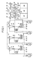
- Fig. 1 is a schematic view showing the entire arrangement of a milling system according to an embodiment of the invention;
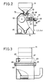
- Fig. 2 is a partially broken-away, front elevational view of a roll mill illustrated in Fig. 1;
- Fig. 3 is a partially broken-away, side elevational view of the roll mill illustrated in Fig. 2;
- Fig. 4 is a fragmentary side elevational view of a measuring device for measuring a milling degree of milled material, illustrated in Fig. 1;
- Fig. 5 is a view of the measuring device illustrated in Fig. 4; and
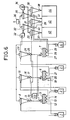
- Fig. 6 is a view similar to Fig. 1, but showing a modification of the invention.
- The invention will now be described, by way of mere example, with reference to the accompanying drawings.
- Referring first to Fig. 1, there is shown the entire arrangement of a milling system according to an embodiment of the invention. The milling system comprises main components which include four roll mills or
flour mills sieve sorters fourth roll mill 4. Each of the milling apparatuses includes theroll mill measuring device - The
first roll mill 1 communicates with acyclone 8, by means of pneumatic transportation. Thecyclone 8 has, at its bottom, an air-lock valve 9. Adirectional control valve 10 arranged downstream of the air-lock valve 9 communicates with the measuring device 11 for measuring a milling degree of milled material such that a part of milled particules is supplied to the measuring device 11. The measuring device 11 communicates with a supply port of thefirst sieve sorter 5. Thedirectional control valve 10 also communicates directly with thesieve sorter 5. - In the illustrated embodiment, the
sieve sorter 5 can sort and separate the milled particles in three stages dependent upon particle size of the milled particles. Specifically, thesieve sorter 5 has a large-particle discharge port 12, an intermediate-particle discharge port 13 and a small-particle discharge port 14. The large-particle discharge port 12, the intermediate-particle discharge port 13 and the small-particle discharge port 13 communicate respectively with a supply port of thefirst roll mill 1, a supply port of thesecond roll mill 2 and acyclone 15. - The
second roll mill 2 communicates with thecyclone 15, by means of pneumatic transportation. Thecyclone 15 has, at its bottom, an air-lock valve 16. Adirectional control valve 17 arranged downstream of the air-lock valve 16 communicates with themeasuring device 18 for measuring a milling degree of the milled material such that a part of the milled particles is suitably supplied to themeasuring device 18. Themeasuring device 18 communicates with a supply port of thesecond sieve sorter 6. Thedirectional control valve 17 also communicates directly with thesieve sorter 6. - The
sieve sorter 6 can sort and separate the milled particles in three stages dependent upon particle size of the milled particles. Specifically, thesieve sorter 6 has a large-particle discharge port 19, an intermediate-particle discharge port 20 and a small-particle discharge port 21. The large-particle discharge port 19, the intermediate-particle discharge port 20 and the small-particle discharge port 21 communicate respectively with the supply port of thesecond roll mill 2, a supply port of thethird roll mill 3 and acyclone 22. - The
third roll mill 3 communicates with acyclone 23, by means of pneumatic transportation. Thecyclone 23 has, its bottom, an air-lock valve 24. Adirectional control valve 25 arranged downstream of the air-lock valve 24 communicates with themeasuring device 26 for measuring a milling degree of the milled material such that a part of the milled particles is suitably supplied to themeasuring device 26. Themeasuring device 26 communicates with a supply port of the third sieve sorter 7. Thedirectional control valve 25 also communicates directly with the third sieve sorter 7. - The third sieve sorter 7 can sort and separate the milled particles in three stages dependent upon particle size of the milling particles. Specifically, the third sieve sorter 7 has a large-
particle discharge port 27, an intermediate-particle discharge port 28 and a small-particle discharge port 29. The large-particle discharge port 27, the intermediate-particle discharge port 28 and the small-particle discharge port 29 communicate respectively with a supply port of thefourth roll mill 4, acyclone 30 and acyclone 31. Thefourth roll mill 4 communicates with thecyclone 23, by means of pneumatic transportation. - The
cyclones cyclone 33 through ablower 32 such that exhaust air from thecyclones cyclone 33. Thecyclones cyclone 35 through ablower 34 such that exhaust air from thecyclones cyclone 35. Thecyclones bag filter 36 such that exhaust air from thecyclones cyclones lock valves lock valve 37 communicates with a supply port of apowder receiving tank 42 for accumulating the milled material thereinto. The air-lock valves powder receiving tank 43 for accumulating the milled material thereinto. Likewise, the air-lock valve 38 communicates with a supply port of apowder receiving tank 44 for accumulating the milled material thereinto. - The first through
fourth roll mills 1 through 4 will next be described with reference to Figs. 2 and 3. - Each of the first through
fourth roll mills 1 through 4 comprises a milling chamber within which a pair ofrolls rolls 63 is movable toward and away from theother roll 62 so that a gap between the pair ofrolls rolls - Associated with the
roll 63 is agap adjusting device 64 which comprises drive means or a reversibleelectric motor 65. Rotation of thereversible motor 65 is converted into reciprocal movement of a pair of adjusting shafts 70 (only one shown) through a pair of sprockets 66 (only one shown) and achain 67. The adjustingshafts 70 are connected to ashaft 68 for theroll 63 through a pair of blocks 77 (only one shown) which are arranged respectively within a pair of adjusting frames 69 (only one shown) fixedly mounted respectively to both side walls of theroll mill - Granular material to be milled is supplied to the
roll mill supply hopper 71 which is mounted to an upper portion of the roll mill. A feedingroll 72 and acontrol valve 73, which are arranged at an outlet port of thehopper 71, cooperate with each other to feed an appropriate amount of the granular material. - The milling chamber within the
roll mill discharge chute 74 for pneumatic transportation. The milling chamber has, at its bottom, a mainelectric motor 75 for rotatively driving the pair ofrolls - In the illustrated embodiment, the
gap adjusting device 64 comprises the reversibleelectric motor 65. However, it is needless to say that, in place of theelectric motor 65, cylinders or the like may be utilized which pneumatically or hydraulically control theshaft 68 for theroll 63. - The measuring
devices - The
roll mill cyclone directional control valve lock valve cyclone directional control valve electromagnetic solenoid 45. Milled granular material from thecyclone supply duct 46, and is supplied to the measuringdevice - The measuring
device image sensor 86 which is arranged in facing relation to thesupply duct 46. Theimage sensor 86 may be a CCD camera which is provided with a function of high-speed electronic shutter. Theimage sensor 86 obtains picture signals from the milled material which flow through thesupply duct 46, on the basis of projected areas of the milled material. Theimage sensor 86 catches milled particles under transportation thereof through thesupply duct 46, whereby the picture signals of the milled particles are treated as a number of picture elements, by an A/D and D/A converter 87 as illustrated in Fig. 5. The number of picture elements is converted into projected equivalent circles by control means or a central processing unit (CPU) 88, to obtain a particle size of the milled material. The particle size of the milled material is compared with a value which is set beforehand in theCPU 88. The comparison at theCPU 88 generates an output signal which is sent to drive means or adrive circuit 89. An output signal from thedrive circuit 89 is sent to thereversible motor 65 of thegap adjusting device 64. The output signal from thedrive circuit 89 is also sent to solenoids or the like which drive shutters for thetanks - In the illustrated embodiment, the measuring
devices directional control valves sieve sorters directional control valves sieve sorters respective cyclones respective sieve sorters devices - The operation of the milling system constructed as above will be described with reference to Fig. 1.
- Granular material to be milled such as wheat or the like is first supplied to the
first roll mill 1 and is milled thereby to form milled particles. The milled particles are fed to thecyclone 8 by pneumatic transportation The milled particles from thecyclone 8 are supplied to thesieve sorter 5 through the air-lock valve 9 and thedirectional control valve 10. Thesieve sorter 5 comprises a plurality of sieve screens different in mesh from each other, which are stacked with each other. The sieve screens are oscillated to sort and separate the milled particles into large particles, intermediate particles and small particles which are discharged respectively through the large-particle discharge port 12, the intermediate-particle discharge port 13 and the small-particle discharge port 14. The large particles are returned to the supply hopper of thefirst roll mill 1. The intermediate particles are fed to the supply hopper of thesecond roll mill 2. The small particles are supplied to thecyclone 15. - The milled particles supplied to the
second roll mill 2 is supplied to thecyclone 15, and are fed to thesecond sieve sorter 6 through the air-lock valve 16 and thedirectional control valve 17. Thesecond sieve sorter 6 also sorts and separates the milled particles into large, intermediate and small particles which are discharged respectively through the large-particle discharge port 19, the intermediate-particle discharge port 20 and the small-particle discharge port 21. The large particles are returned to the supply hopper of thesecond roll mill 2. The intermediate particles are supplied to the supply hopper of thethird roll mill 3. The small particles are supplied to thecyclone 22 where the small particles are sorted by air flow and are accumulated into thetank 42 as milled material, through the air-lock valve 37. - The milled particles, which are supplied to the
third roll mill 3 and are milled thereby, are supplied to thecyclone 23, and are fed to the third sieve sorter 7 through the air-lock valve 24 and thedirectional control valve 25. The third sieve sorter 7 also sorts and separates the milled particles into large, intermediate and small particles which are discharged respectively through the large-particle discharge port 27, the intermediate-particle discharge port 28 and the small-particle discharge port 29. The large particles are supplied to the supply hopper of thefourth roll mill 4. The intermediate particles are supplied to thecyclone 30 where the intermediate particles are sorted by air flow and are accumulated as milled material into thetank 44 through the air-lock valve 38. The small particles are supplied to thecyclone 31 where the small particles are sorted by air flow and are accumulated into thetank 43 as milled material, through the air-lock valve 39. Exhaust air from thecyclones cyclone 33 through theblower 32, and exhaust air from thecyclones blower 34, to thecyclone 35. At thecyclones tank 43 as milled material, through the air-lock valves cyclones bag filter 36. - The operation of the measuring
devices - The milled particles suitably supplied through the
supply duct 46 by thedirectional control valve image sensor 86. The output signal from theimage sensor 86 is sent to the A/D and D/A converter 87 where the projected areas of the milled particles are analyzed one by one as the number of picture elements. From the equation in which the number of picture elements = πr², theCPU 88 converts the number of picture elements into the particulate size of one grain. A desirable milling degree or a desirable particulate size is beforehand set in theCPU 88. An amount of distribution or a particulate-degree distribution of the milled particles for various particulate sizes on the basis of the converted particulate sizes of the individual milled particles is compared with a setting value or the aforesaid set milling degree. If the particulate sizes corresponding to a peak of the particulate-degree distribution are larger than the setting value, the milling degree of the milled particles is low. This means that the gap between the pair ofrolls CPU 88 issues the output signal to thedrive circuit 89 which gives the output signal to thereversible motor 65 such that the gap between the pair ofrolls rolls CPU 88 generates the output signal to thedrive circuit 89 which gives the output signal to thereversible motor 65 such that the gap between the pair ofrolls
Claims (20)
a roll mill (1, 2, 3) for milling the granular material into milled particles, the roll mill including a pair of rolls (62, 63) which are rotatably arranged in facing relation to each other, at least one of the pair of rolls (63) being movable toward and away from the other (62), and gap adjusting means (64) associated with said at least one roll for moving the same toward and away from the other roll to adjust a gap between said pair of rolls thereby adjusting a milling degree of the milled particles; and
measuring means (11, 18, 26; 111) arranged downstream of said roll mill (1, 2, 3) and connected to said gap adjusting means (64) thereof for measuring the milling degree of the milled particles to issue an output signal representative of the milling degree,
wherein said gap adjusting means (64) is operative in response to said output signal from said measuring means (11, 18, 26; 111) to move said at least one roll (63) toward and away from the other roll (62), thereby automatically adjusting the milling degree of the milled particles.
at least two, first and second roll mills (1, 2, 3) for milling the granular material into milled particles, each of said first and second roll mills including a pair of rolls (62, 63) which are rotatably arranged in facing relation to each other, at least one of said pair of rolls (63) being movable toward and away from the other (62), and gap adjusting means (64) associated with said at least one roll for moving the same toward and away from the other roll to adjust a gap between said pair of rolls thereby adjusting a milling degree of the milled particles;
at least one measuring means (11, 18, 26; 111) arranged downstream of said first and second roll mills (1, 2, 3) and connected to said gap adjusting means (64) thereof for measuring the milling degree of the milled particles sent from the respective first and second roll mills, to issue output signals representative of the respective milling degrees,
wherein said gap adjusting means (64) of each of said first and second roll mills (1, 2, 3) is operative in response to a corresponding one of said output signals from said measuring means (11, 18, 26; 111) to move the at least one roll (63) toward and away from the other roll (62), thereby automatically adjusting a corresponding one of the milling degrees of the milled particles.
Priority Applications (5)
| Application Number | Priority Date | Filing Date | Title |
|---|---|---|---|
| EP89313019A EP0433498B1 (en) | 1989-12-13 | 1989-12-13 | Milling apparatus and system therefor |
| DE68918701T DE68918701T2 (en) | 1989-12-13 | 1989-12-13 | Grinding device and system therefor. |
| AU46864/89A AU616087B2 (en) | 1989-12-13 | 1989-12-15 | Milling apparatus and system therefor |
| CA002005730A CA2005730C (en) | 1989-12-13 | 1989-12-15 | Milling apparatus and system therefor |
| US07/452,271 US5050808A (en) | 1989-12-13 | 1989-12-18 | Milling apparatus and system therefor |
Applications Claiming Priority (2)
| Application Number | Priority Date | Filing Date | Title |
|---|---|---|---|
| EP89313019A EP0433498B1 (en) | 1989-12-13 | 1989-12-13 | Milling apparatus and system therefor |
| CA002005730A CA2005730C (en) | 1989-12-13 | 1989-12-15 | Milling apparatus and system therefor |
Publications (2)
| Publication Number | Publication Date |
|---|---|
| EP0433498A1 true EP0433498A1 (en) | 1991-06-26 |
| EP0433498B1 EP0433498B1 (en) | 1994-10-05 |
Family
ID=25673837
Family Applications (1)
| Application Number | Title | Priority Date | Filing Date |
|---|---|---|---|
| EP89313019A Revoked EP0433498B1 (en) | 1989-12-13 | 1989-12-13 | Milling apparatus and system therefor |
Country Status (5)
| Country | Link |
|---|---|
| US (1) | US5050808A (en) |
| EP (1) | EP0433498B1 (en) |
| AU (1) | AU616087B2 (en) |
| CA (1) | CA2005730C (en) |
| DE (1) | DE68918701T2 (en) |
Cited By (19)
| Publication number | Priority date | Publication date | Assignee | Title |
|---|---|---|---|---|
| EP0615789A3 (en) * | 1990-09-14 | 1997-08-06 | Buehler Ag | Method for sorting bulk particles and device for that purpose. |
| WO1997041956A1 (en) * | 1996-05-03 | 1997-11-13 | Braibanti Golfetto S.P.A. | Method for automatically controlling grinding within a milling plant, and plant for implementing the method |
| WO2001003841A1 (en) * | 1999-07-08 | 2001-01-18 | Imeco Automazioni S.R.L. | System and self-moving device for the control of milling processes |
| WO2006000112A1 (en) * | 2004-06-25 | 2006-01-05 | Bühler AG | System and method for characterising grinding material in a roller mill |
| EP1690596A1 (en) * | 2005-02-15 | 2006-08-16 | Franzoi Metalmeccanica S.R.L. | Shredder for refuse materials |
| WO2006116882A1 (en) * | 2005-05-02 | 2006-11-09 | Bühler AG | System and method for characterisation of a particle flow |
| EA011849B1 (en) * | 2004-06-25 | 2009-06-30 | Бюлер Аг | System and method for characterisation of a particle flow |
| WO2010000811A3 (en) * | 2008-07-02 | 2010-02-25 | Bühler AG | Apparatus and method for producing flour and/or semolina |
| WO2011061420A1 (en) | 2009-11-20 | 2011-05-26 | Chopin Technologies | Method and device having a simplified construction for the reference grinding of wheat |
| KR101168024B1 (en) | 2012-01-18 | 2012-07-27 | (주)큰나무 | Crusher |
| CN103639010A (en) * | 2013-12-16 | 2014-03-19 | 柳州职业技术学院 | Novel flour mill |
| CN108325614A (en) * | 2018-05-04 | 2018-07-27 | 王小龙 | The adjustable crusher of discaling roll |
| WO2022178607A1 (en) * | 2021-02-23 | 2022-09-01 | Bunge Sa | Modular system for a grain cracker and a grain cracking system and method |
| US12319976B2 (en) | 2021-11-04 | 2025-06-03 | Suncoke Technology And Development Llc | Foundry coke products, and associated systems, devices, and methods |
| US12325828B2 (en) | 2012-12-28 | 2025-06-10 | Suncoke Technology And Development Llc | Exhaust flow modifier, duct intersection incorporating the same, and methods therefor |
| WO2025122901A1 (en) * | 2023-12-06 | 2025-06-12 | Suncoke Technology And Development Llc | Milling systems and methods for producing materials with a particular particle size distribution |
| US12410369B2 (en) | 2023-11-21 | 2025-09-09 | Suncoke Technology And Development Llc | Flat push hot car for foundry coke and associated systems and methods |
| US12553004B2 (en) | 2021-05-04 | 2026-02-17 | Suncoke Technology And Development Llc | Foundry coke products, and associated systems and methods |
| US12600915B2 (en) | 2020-05-03 | 2026-04-14 | Suncoke Technology And Development Llc | High-quality coke products |
Families Citing this family (15)
| Publication number | Priority date | Publication date | Assignee | Title |
|---|---|---|---|---|
| US5261285A (en) * | 1990-08-02 | 1993-11-16 | Hajime Industries Ltd. | Powder granule sample inspection apparatus |
| US5027491A (en) * | 1990-08-16 | 1991-07-02 | Mclanahan Corporation | Roller |
| WO1993019848A1 (en) * | 1992-04-06 | 1993-10-14 | Reeter Dan E | Method and apparatus for mixing, comminuting and/or separating recyclable materials |
| US5379948A (en) * | 1994-01-06 | 1995-01-10 | American Colloid Company | Method for milling clay without substantial generation of powder |
| JPH1033997A (en) * | 1996-07-22 | 1998-02-10 | Satake Eng Co Ltd | Detachment device |
| DE19845363A1 (en) | 1998-10-02 | 2000-04-27 | Kima Ges Fuer Echtzeitsysteme | On-line particle size measuring device |
| JP4692794B2 (en) * | 2000-06-07 | 2011-06-01 | 株式会社サタケ | Removal device |
| CN100363107C (en) * | 2002-12-02 | 2008-01-23 | 布勒公司 | Roll-type sheller for grain |
| US7279037B2 (en) * | 2004-02-12 | 2007-10-09 | Engelhard Corporation | Process and products of chinese kaolin |
| JP4483692B2 (en) * | 2005-05-09 | 2010-06-16 | 株式会社サタケ | De-rolling roll drive device in de-pulling machine |
| DE102008040095A1 (en) * | 2008-07-02 | 2010-01-07 | Bühler AG | Control system for grain processing plant |
| CN101829615B (en) * | 2010-03-31 | 2015-05-27 | 无锡市新科表面工程材料有限公司 | Rolling machine for grinding materials |
| EP3292912B1 (en) * | 2016-09-09 | 2019-12-25 | Loesche GmbH | Method for operating a multicyclone for separating fine and micro grain and multicyclone |
| CN112169976A (en) * | 2018-08-31 | 2021-01-05 | 兰秋霞 | Automatic concrete processing system for building construction |
| CN110270399A (en) * | 2019-07-01 | 2019-09-24 | 枣庄鑫金山智能机械股份有限公司 | A kind of sand making machine setting crushing rotary drum gap adjusting mechanism |
Citations (3)
| Publication number | Priority date | Publication date | Assignee | Title |
|---|---|---|---|---|
| CH528302A (en) * | 1971-08-11 | 1972-09-30 | Vnii Zerna I Produktov Ego Per | Laboratory flour mill |
| GB2040506A (en) * | 1979-01-23 | 1980-08-28 | Satake Eng Co Ltd | Automatic Control for a Hulling Machine |
| WO1986005416A1 (en) * | 1985-03-15 | 1986-09-25 | Gebrüder Bühler Ag | Process for the adjustment of the grinding rollers of a grain mill installation; also, a grain mill installation for carrying out the process |
Family Cites Families (10)
| Publication number | Priority date | Publication date | Assignee | Title |
|---|---|---|---|---|
| US2879004A (en) * | 1954-12-07 | 1959-03-24 | Safety Ind Inc | Centrifugal impact milling process of impact milling |
| US2984423A (en) * | 1956-08-23 | 1961-05-16 | Buehler Ag Geb | Control device for roller mill |
| DE1224935B (en) * | 1964-12-09 | 1966-09-15 | Stolberger Zink Ag | Process and system for the processing of lead-containing batteries |
| ZA747312B (en) * | 1973-11-17 | 1975-12-31 | Kloeckner Humboldt Deutz Ag | Method of determining and setting the width of the crushing gap and of measuring crushing tool wear in a a rotary crushing by aultrsonicmeans, and torary crusher for carrying out the method |
| US4133899A (en) * | 1976-03-16 | 1979-01-09 | Nabisco, Inc. | Farina milling process |
| DE2855715C3 (en) * | 1978-12-22 | 1982-05-19 | Gebrüder Bühler AG, 9240 Uzwil | Grain mill plant for the production of flour |
| US4338024A (en) * | 1980-05-02 | 1982-07-06 | International Remote Imaging Systems, Inc. | Flow analyzer and system for analysis of fluids with particles |
| CH653862A5 (en) * | 1981-09-16 | 1986-01-31 | Buehler Ag Geb | ROLLING MILL WITH AT LEAST FOUR ROLLS. |
| JPS6137629A (en) * | 1984-07-30 | 1986-02-22 | Asahi Breweries Ltd | Method and device for preventing clogging in light powder and granule processing equipment |
| US4817441A (en) * | 1988-05-02 | 1989-04-04 | O'donnell & Associates, Inc. | Process and apparatus for obtaining a gas sample |
-
1989
- 1989-12-13 DE DE68918701T patent/DE68918701T2/en not_active Revoked
- 1989-12-13 EP EP89313019A patent/EP0433498B1/en not_active Revoked
- 1989-12-15 CA CA002005730A patent/CA2005730C/en not_active Expired - Fee Related
- 1989-12-15 AU AU46864/89A patent/AU616087B2/en not_active Ceased
- 1989-12-18 US US07/452,271 patent/US5050808A/en not_active Expired - Lifetime
Patent Citations (3)
| Publication number | Priority date | Publication date | Assignee | Title |
|---|---|---|---|---|
| CH528302A (en) * | 1971-08-11 | 1972-09-30 | Vnii Zerna I Produktov Ego Per | Laboratory flour mill |
| GB2040506A (en) * | 1979-01-23 | 1980-08-28 | Satake Eng Co Ltd | Automatic Control for a Hulling Machine |
| WO1986005416A1 (en) * | 1985-03-15 | 1986-09-25 | Gebrüder Bühler Ag | Process for the adjustment of the grinding rollers of a grain mill installation; also, a grain mill installation for carrying out the process |
Cited By (31)
| Publication number | Priority date | Publication date | Assignee | Title |
|---|---|---|---|---|
| EP0615789A3 (en) * | 1990-09-14 | 1997-08-06 | Buehler Ag | Method for sorting bulk particles and device for that purpose. |
| US6012661A (en) * | 1996-05-02 | 2000-01-11 | Braibanti Golfetto S.P.A. | Method for automatically controlling grinding within a milling plant, and plant for implementing the method |
| WO1997041956A1 (en) * | 1996-05-03 | 1997-11-13 | Braibanti Golfetto S.P.A. | Method for automatically controlling grinding within a milling plant, and plant for implementing the method |
| WO2001003841A1 (en) * | 1999-07-08 | 2001-01-18 | Imeco Automazioni S.R.L. | System and self-moving device for the control of milling processes |
| WO2006000112A1 (en) * | 2004-06-25 | 2006-01-05 | Bühler AG | System and method for characterising grinding material in a roller mill |
| EA011313B1 (en) * | 2004-06-25 | 2009-02-27 | Бюлер Аг | System and method for characterising grinding stock rate in a roller mill and roller mill |
| EA011849B1 (en) * | 2004-06-25 | 2009-06-30 | Бюлер Аг | System and method for characterisation of a particle flow |
| EP1690596A1 (en) * | 2005-02-15 | 2006-08-16 | Franzoi Metalmeccanica S.R.L. | Shredder for refuse materials |
| WO2006116882A1 (en) * | 2005-05-02 | 2006-11-09 | Bühler AG | System and method for characterisation of a particle flow |
| RU2498854C2 (en) * | 2008-07-02 | 2013-11-20 | Бюлер Аг | Method of flour production from grain, roll mill, application of roll mill, zigzag sieving machine and its application |
| US10981177B2 (en) | 2008-07-02 | 2021-04-20 | Bühler AG | Apparatus and method for producing flour and/or semolina |
| WO2010000811A3 (en) * | 2008-07-02 | 2010-02-25 | Bühler AG | Apparatus and method for producing flour and/or semolina |
| US9067213B2 (en) | 2008-07-02 | 2015-06-30 | Buhler Ag | Method for producing flour and/or semolina |
| FR2953742A1 (en) * | 2009-11-20 | 2011-06-17 | Chopin Technologies | METHOD AND APPARATUS FOR SIMPLIFIED MANUFACTURING OF REFERENCE WHITE MILL |
| CN102834177A (en) * | 2009-11-20 | 2012-12-19 | 肖邦技术公司 | Method and device having a simplified construction for the reference grinding of wheat |
| WO2011061420A1 (en) | 2009-11-20 | 2011-05-26 | Chopin Technologies | Method and device having a simplified construction for the reference grinding of wheat |
| US9067210B2 (en) | 2009-11-20 | 2015-06-30 | Chopin Technologies | Method and device having a simplified constructions for the reference grinding of wheat |
| CN102834177B (en) * | 2009-11-20 | 2015-11-25 | 肖邦技术公司 | The simplified production method of standard wheat flour and equipment |
| KR101168024B1 (en) | 2012-01-18 | 2012-07-27 | (주)큰나무 | Crusher |
| US12325828B2 (en) | 2012-12-28 | 2025-06-10 | Suncoke Technology And Development Llc | Exhaust flow modifier, duct intersection incorporating the same, and methods therefor |
| CN103639010A (en) * | 2013-12-16 | 2014-03-19 | 柳州职业技术学院 | Novel flour mill |
| CN108325614B (en) * | 2018-05-04 | 2019-10-11 | 唐山冀东发展机械设备制造有限公司 | The adjustable crusher of discaling roll |
| CN108325614A (en) * | 2018-05-04 | 2018-07-27 | 王小龙 | The adjustable crusher of discaling roll |
| US12600915B2 (en) | 2020-05-03 | 2026-04-14 | Suncoke Technology And Development Llc | High-quality coke products |
| WO2022178607A1 (en) * | 2021-02-23 | 2022-09-01 | Bunge Sa | Modular system for a grain cracker and a grain cracking system and method |
| CN117460580A (en) * | 2021-02-23 | 2024-01-26 | 邦格公司 | Modular system for grain crusher and grain crushing system and method |
| US12553004B2 (en) | 2021-05-04 | 2026-02-17 | Suncoke Technology And Development Llc | Foundry coke products, and associated systems and methods |
| US12319976B2 (en) | 2021-11-04 | 2025-06-03 | Suncoke Technology And Development Llc | Foundry coke products, and associated systems, devices, and methods |
| US12331367B2 (en) | 2021-11-04 | 2025-06-17 | Suncoke Technology And Development Llc | Foundry coke products, and associated systems, devices, and methods |
| US12410369B2 (en) | 2023-11-21 | 2025-09-09 | Suncoke Technology And Development Llc | Flat push hot car for foundry coke and associated systems and methods |
| WO2025122901A1 (en) * | 2023-12-06 | 2025-06-12 | Suncoke Technology And Development Llc | Milling systems and methods for producing materials with a particular particle size distribution |
Also Published As
| Publication number | Publication date |
|---|---|
| EP0433498B1 (en) | 1994-10-05 |
| AU4686489A (en) | 1991-06-20 |
| AU616087B2 (en) | 1991-10-17 |
| DE68918701T2 (en) | 1995-02-09 |
| CA2005730C (en) | 1995-12-19 |
| US5050808A (en) | 1991-09-24 |
| DE68918701D1 (en) | 1994-11-10 |
| CA2005730A1 (en) | 1991-06-15 |
Similar Documents
| Publication | Publication Date | Title |
|---|---|---|
| US5050808A (en) | Milling apparatus and system therefor | |
| US9067213B2 (en) | Method for producing flour and/or semolina | |
| US10478860B2 (en) | Device and method for the flexible classification of polycrystalline silicon fragments | |
| JP5360374B2 (en) | Grain sorter | |
| US5733592A (en) | Method for cleaning and sorting bulk material | |
| US5699724A (en) | Cleaning and sorting bulk material | |
| US4634522A (en) | Arrangement in machines for separating materials having different aerodynamic properties | |
| CN113117857B (en) | Intelligent crushing integrated system for continuous graded recycled aggregate | |
| EP0615789B1 (en) | Method for sorting bulk particles and device for that purpose | |
| JP3382620B2 (en) | Control method of closed-circuit dry mill | |
| US20050189262A1 (en) | Apparatus and methods for controlling the separation of particulate material | |
| JP2002239465A (en) | Grain sealed wind sorter | |
| JP2710039B2 (en) | Grinding degree control device for crusher | |
| JPH02111448A (en) | Automatic adjusting device for degree of grinding by measuring projection area of powder | |
| KR950012300B1 (en) | Milling device and system | |
| CN108348923B (en) | Pneumatically connected cascade screeners and circulating grinding plants with pneumatically connected cascade screeners | |
| JP2556531Y2 (en) | Granular grain sorting equipment | |
| WO2006116882A1 (en) | System and method for characterisation of a particle flow | |
| JPS62213853A (en) | Crushing degree automatic controller of crusher | |
| JPH1066892A (en) | Crushed sand production equipment | |
| JP3704860B2 (en) | Kernel drying facility | |
| RU27797U1 (en) | TECHNOLOGICAL LINE FOR PRODUCING VARIETY FLOUR FROM GRAIN CROPS | |
| WO1997041956A1 (en) | Method for automatically controlling grinding within a milling plant, and plant for implementing the method | |
| JP2651423B2 (en) | Operation method of roll milling equipment | |
| US3080125A (en) | Process for manufacturing wheat flour |
Legal Events
| Date | Code | Title | Description |
|---|---|---|---|
| PUAI | Public reference made under article 153(3) epc to a published international application that has entered the european phase |
Free format text: ORIGINAL CODE: 0009012 |
|
| AK | Designated contracting states |
Kind code of ref document: A1 Designated state(s): CH DE GB IT LI NL |
|
| 17P | Request for examination filed |
Effective date: 19911202 |
|
| 17Q | First examination report despatched |
Effective date: 19930210 |
|
| GRAA | (expected) grant |
Free format text: ORIGINAL CODE: 0009210 |
|
| AK | Designated contracting states |
Kind code of ref document: B1 Designated state(s): CH DE GB IT LI NL |
|
| REF | Corresponds to: |
Ref document number: 68918701 Country of ref document: DE Date of ref document: 19941110 |
|
| ITF | It: translation for a ep patent filed | ||
| PLBI | Opposition filed |
Free format text: ORIGINAL CODE: 0009260 |
|
| 26 | Opposition filed |
Opponent name: BUEHLER AG Effective date: 19950608 |
|
| NLR1 | Nl: opposition has been filed with the epo |
Opponent name: BUEHLER AG |
|
| PLBF | Reply of patent proprietor to notice(s) of opposition |
Free format text: ORIGINAL CODE: EPIDOS OBSO |
|
| PLBF | Reply of patent proprietor to notice(s) of opposition |
Free format text: ORIGINAL CODE: EPIDOS OBSO |
|
| PLBF | Reply of patent proprietor to notice(s) of opposition |
Free format text: ORIGINAL CODE: EPIDOS OBSO |
|
| PGFP | Annual fee paid to national office [announced via postgrant information from national office to epo] |
Ref country code: GB Payment date: 19961204 Year of fee payment: 8 |
|
| PGFP | Annual fee paid to national office [announced via postgrant information from national office to epo] |
Ref country code: CH Payment date: 19961219 Year of fee payment: 8 |
|
| PGFP | Annual fee paid to national office [announced via postgrant information from national office to epo] |
Ref country code: DE Payment date: 19961223 Year of fee payment: 8 |
|
| PGFP | Annual fee paid to national office [announced via postgrant information from national office to epo] |
Ref country code: NL Payment date: 19961231 Year of fee payment: 8 |
|
| RDAH | Patent revoked |
Free format text: ORIGINAL CODE: EPIDOS REVO |
|
| RDAG | Patent revoked |
Free format text: ORIGINAL CODE: 0009271 |
|
| STAA | Information on the status of an ep patent application or granted ep patent |
Free format text: STATUS: PATENT REVOKED |
|
| REG | Reference to a national code |
Ref country code: CH Ref legal event code: PL |
|
| 27W | Patent revoked |
Effective date: 19970619 |
|
| GBPR | Gb: patent revoked under art. 102 of the ep convention designating the uk as contracting state |
Free format text: 970619 |
|
| NLR2 | Nl: decision of opposition |