EP0433492B1 - Ultrasonic device for the virtual reduction of the array partition of a connectable transducer array - Google Patents
Ultrasonic device for the virtual reduction of the array partition of a connectable transducer array Download PDFInfo
- Publication number
- EP0433492B1 EP0433492B1 EP89123788A EP89123788A EP0433492B1 EP 0433492 B1 EP0433492 B1 EP 0433492B1 EP 89123788 A EP89123788 A EP 89123788A EP 89123788 A EP89123788 A EP 89123788A EP 0433492 B1 EP0433492 B1 EP 0433492B1
- Authority
- EP
- European Patent Office
- Prior art keywords
- transmission
- reception
- channels
- group
- adders
- Prior art date
- Legal status (The legal status is an assumption and is not a legal conclusion. Google has not performed a legal analysis and makes no representation as to the accuracy of the status listed.)
- Expired - Lifetime
Links
Images

Classifications
-
- G—PHYSICS
- G01—MEASURING; TESTING
- G01S—RADIO DIRECTION-FINDING; RADIO NAVIGATION; DETERMINING DISTANCE OR VELOCITY BY USE OF RADIO WAVES; LOCATING OR PRESENCE-DETECTING BY USE OF THE REFLECTION OR RERADIATION OF RADIO WAVES; ANALOGOUS ARRANGEMENTS USING OTHER WAVES
- G01S7/00—Details of systems according to groups G01S13/00, G01S15/00, G01S17/00
- G01S7/52—Details of systems according to groups G01S13/00, G01S15/00, G01S17/00 of systems according to group G01S15/00
- G01S7/52017—Details of systems according to groups G01S13/00, G01S15/00, G01S17/00 of systems according to group G01S15/00 particularly adapted to short-range imaging
- G01S7/52046—Techniques for image enhancement involving transmitter or receiver
- G01S7/52047—Techniques for image enhancement involving transmitter or receiver for elimination of side lobes or of grating lobes; for increasing resolving power
-
- G—PHYSICS
- G10—MUSICAL INSTRUMENTS; ACOUSTICS
- G10K—SOUND-PRODUCING DEVICES; METHODS OR DEVICES FOR PROTECTING AGAINST, OR FOR DAMPING, NOISE OR OTHER ACOUSTIC WAVES IN GENERAL; ACOUSTICS NOT OTHERWISE PROVIDED FOR
- G10K11/00—Methods or devices for transmitting, conducting or directing sound in general; Methods or devices for protecting against, or for damping, noise or other acoustic waves in general
- G10K11/18—Methods or devices for transmitting, conducting or directing sound
- G10K11/26—Sound-focusing or directing, e.g. scanning
- G10K11/34—Sound-focusing or directing, e.g. scanning using electrical steering of transducer arrays, e.g. beam steering
- G10K11/341—Circuits therefor
- G10K11/345—Circuits therefor using energy switching from one active element to another
Definitions
- the invention relates to an ultrasound device with a first group of transmission and reception channels, each of which is assigned to an elementary converter in the active aperture of a connectable converter array, the central transmission location generated by a transmission channel and the central reception location queried by a reception channel being located on the assigned elementary converter .
- a fine array division is the basis for an image display with high resolution.
- very high-frequency arrays 7.5 MHz
- technological limits because elementary converters become very narrow, e.g. B. in manufacture, the number of elementary converters can not be increased arbitrarily in array systems.
- technological limits when manufacturing high-frequency arrays with operating frequencies greater than approx. 7 MHz because the elementary converters become very narrow.
- the result is that grating legs appear disruptively. Grating lobes arise due to the finite spatial quantization by the array division or, in another interpretation, by diffraction at the grid of the array division.
- the invention is therefore based on the object of increasing the dynamics of the point image function for a given array division.
- the device's ability to detect small differences in contrast should therefore be increased.
- a second group of transmission and / or reception channels is additionally present, each with a plurality of elementary converters via transmission and / or reception transfer means for simultaneously generating a central transmission and / or reception location lying between the elementary converters are connectable.
- central transmitting and receiving locations located on the transducers central transmitting and / or receiving locations lying virtually between elementary transducers are generated.
- the array division is thus virtually refined or the elementary transducer density the array appears to be almost doubled.
- Grating legs are less disruptive.
- the dynamics of the point spread function are increased, the device can recognize small differences in contrast more precisely.
- An advantageous embodiment is characterized by the characterizing features of claim 8. To generate the send and receive location on the assigned transducer, only this transducer itself is activated, as is also the case in the prior art cited at the beginning. The transmitting and receiving locations that are virtually between the physically present transducers are each generated by simultaneous activation of the transducers located adjacent to them. Alternately, one or two elementary converters are controlled or queried at the same time.
- a further advantageous embodiment is characterized by the features of claim 10.
- the change of the elementary converters that are controlled or queried at the same time is extended to two or three.
- a compensation of the different sensitivity, which is caused by the alternating activation of two or elementary converters, is less necessary here than in the variant in which one or two elementary converters are activated alternately.
- a converter array can be used unchanged with a division according to the current state of the art.
- the virtual generation of an array division that is almost twice as fine, the resolution in the image display is significantly improved.
- Another advantage is that converter arrays that are already available to the user can be connected to devices as proposed here. In any case, a significant gain in the dynamics of the point spread function compared to a device with a "small number of channels" is achieved.
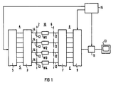
- the transmission side 4 is shown on the left of a dash-dotted line 2 and the reception side 8 of the ultrasound device is shown on the right of a dash-dotted line 6.
- An ultrasound applicator with a transducer array 10 can be connected to the transmitting and receiving sides 4 and 8.
- the transducer array 10 consists of elementary transducers W1, W2, W3 ... arranged in series one behind the other. The connection of the elementary transducers W1, W2, W3 ... with the ultrasound device takes place via connection channels 12.
- connection channels 12 are equal to the number of elementary transducers W1 ... in the active aperture.
- the active aperture In order to carry out a linear scan, the active aperture consists of a group of elementary transducers W1 ..., which is incremented via the array 10 for scanning along parallel scanning beams.
- an active aperture which comprises fewer transducer elements W1 ... than are present in the entire array is also incrementally advanced.
- the active aperture can also include all transducer elements W1 ... of the array 10, which are then controlled to carry out an electronic sector scan with electronic swiveling and / or electronic focusing.
- connection channels 12 are connected to outputs 14 of transmission transfer means 3.
- the transmission transfer means 3 are connected to transmission channels S, the number of which is almost twice as large as the number of connection channels 12.
- the transmission channels S pass on transmission pulses which are generated by a pulse generator 5.
- the pulse generator can, if necessary, shift the transmission pulses on the individual transmission channels S against one another in such a way that electronic swiveling and / or electronic focusing of the ultrasound scanning takes place in the examination area.
- the structure and function of the transmission transfer means 3 will be explained below with reference to FIGS. 2 and 3.
- the receiving side 8 is constructed similarly to the transmitting side 4.
- the connection channels 12 are connected to reception transfer means 7.
- the reception transfer means 7 are connected to reception channels E, the number of which is almost twice as large as the number of connection channels 12 or converter elements W1 ...
- the number of reception channels E is equal to the number of transmission channels S.
- the structure and function of the Receive transfer means 7 will be explained later with reference to FIGS 2 and 3.
- the reception channels E feed the echo signals to a reception circuit 9, which forms a reception signal from the echo signals from the elementary transducers W1 ... after a suitable delay.
- This received signal is representative of a focused scan along a scan line.
- the delays can also be chosen such that the scanning line has a predeterminable angle to the surface of the array 10, that is to say it is pivoted electronically.
- the received signal of the receiving circuit 9 is further processed in a subsequent signal processing circuit 11. There the signal is processed so that it can be displayed on a screen 13. A sectional image of the examination area as well as individually or additionally blood flow information can be displayed.
- a control unit 15 is provided to control the functions in the ultrasound device. It controls the processes on the transmitting and receiving sides 4 and 8 as well as the image display.
- the transmission channels S1, S2, S3 ... and the reception channels E1, E2, E3 ... of a first group are the elementary converters W1, W2, W3 ... assigned.
- the assignment is that the central sending and receiving location, that is, the origin of the main energy beam direction and the main direction of sensitivity on the elementary transducers W1, W2, W3 ...
- a transmission signal on the transmission channel S1 thus generates a central transmission location which is located on the converter W1.
- the reception signal which strikes the transducer W1 in the main sensitivity direction is essentially passed on to the reception channel E1.
- the central receiving location which is assigned to the receiving channel E1, is thus on the converter W1.
- the transmit and receive channels S2, S3 ... or E2, E3 ... are assigned to the elementary converters W2, W3 ... in the same way.
- E2 ... is a second group of transmission and reception channels S12, S23, S34 ... or E12, E23, E34 ... available.
- the transmission and reception channels of the second group S12 ... and E12 ... are each connected to neighboring elementary transducers W1 and W2 or W2 and W3 ... via the transmission transmission means 3 and reception transmission means 7. If several neighboring elementary transducers W1, W2 ... are excited at the same time, the resulting main energy beam direction results from the axis of symmetry to all the main energy beam directions of the individual transducers W1, W2, etc. If an even number of elementary transducers are excited simultaneously, the origin of the main energy beam direction lies between the Elementary converters, a central transmission location is virtually formed between the elementary converters W1, W2 ...
- the conditions for reception are analogous to sending. If several neighboring elementary transducers W1, W2 ... receive at the same time, the resulting main sensitivity direction results as the axis of symmetry of the main sensitivity directions of the individual transducers W1, W2 ... It is therefore possible to query an even number of elementary transducers W1, W2 ... at the same time. a central receiving location that is virtually located between the elementary transducers W1, W2.
- a connection channel 12 is connected to the output 14 of a transmit adder 16 connected.
- Each transmission channel of the first group S1, S2 ... is connected to an input 18 of a transmission adder 16.
- each transmission channel of the second group S12, S23 ... is connected to an input 18 of two adjacent transmission adders 16.
- reception adders 20 are provided, the outputs 22 of which are each connected to the reception channels of the second group E12, E23 ...
- Each receive adder 20 has two inputs 24, each of which can be connected to two adjacent elementary converters W1, W2 ... via the connection channels 12.
- the reception channels of the first group E1, E2 ... can be connected directly to the corresponding elementary converters W1, W2 ... via the connection channels 12.
- the active aperture of the transducer array 10 consists of n elementary transducers W1 to Wn
- the n transmission channels of the first group S1 to Sn and reception channels E1 to En n generate central transmitting and receiving locations which are located on the elementary transducers W1 to Wn.
- the elementary converters W1 to Wn virtually n-1 transmission and reception locations of n-1 transmission and reception channels of the second group S12 to S (n-1) n or E12 to E (n-1) n are generated.
- the total of 2n-1 central sending and receiving locations are alternately generated by the activation of one or two elementary converters W1 to Wn.
- amplitude attenuators 26 are inserted in the transmit and receive channels of the second group S12 ... or E12 ..., which channels the channels of the first and second Group S1 ... and E1 ... or S12 ... and E12 ... should match in terms of performance. It has been found that the weighting factor with which the amplitudes are weighted by the amplitude attenuators 26 can be between 0.5 and 1.
- FIG 3 again shows an ultrasound device with a transmitting side 4 and a receiving side 8, to which a transducer array 10 can be connected via connection channels 12.
- an active aperture is formed from elementary transducers arranged in series, which, however, are designated W0, W1, W2, W3 ... for reasons of clarity.
- the first group of transmit and receive channels S1, S2 ... or E1, E2 ... is each assigned to an elementary converter W1, W2 ...
- not only the assigned elementary converter but also adjacent elementary converters are each connected to the transmit and receive channels of the first group S1 ... or E1 ....
- the central send and receive location effected by each individual send and receive channel S1 ... or E1 ... is located on the assigned converter W1, W2 ...
- two neighboring elementary transducers W0 and W1, W1 and W2 etc. are each created, each with one transmitting and receiving channel of the second group S01, S12, .. . or E01, E12, ... connected.
- the second group of transmit and receive channels S01 ... or E01 can thus be connected to two adjacent elementary transducers W0 ... just like the second group of the exemplary embodiment according to FIG.
- the elementary converters W0 ... are each connected to an output 14 of a transmission adder 16 via control channels 12.
- the transmit channels of the first group S1 ... are each connected to an input 18 of three adjacent transmit adders 16.
- the transmission channels of the second group S01, S12 ... are each connected to an input 18 of two adjacent transmission adders 16.
- each receive channel E1 ... and E01 is connected to an output 22 of a receive adder 20.
- the receive adders are each connectable with the connection channels 12 of neighboring elementary transformers W0, W1 ... So z. B.
- the receive adder 20 for the receive channel E01 on the input side can be connected to the elementary converters W01 and W1, while the receive adder 20 for the receive channel E1 can be connected on the input side to the elementary converters W0, W1 and W2.
- two or three elementary converters W0, W1 ... are always controlled or queried at the same time.
- 2n-3 transmit and receive channels S1 ... and S01 ... or E1 ... and E01 ... are provided.
- n-2 transmission and reception channels of the first group S1 ... or E1 ... are assigned to the elementary converters W1, W2 ...
- n-1 transmitting and receiving channels of the second group S01 ... or E01 ... are provided.
- the values of the delays of the transmit and receive signals for the virtually generated transmit and receive locations lie between the values of the delay for the transmit and receive locations on the elementary converters.
- the virtual send and receive locations are served at different times than the send and receive locations located on the converters.
- the delay for pan and / or focusing is carried out here as for a converter array with a high number of elementary converters, in which the number of elementary converters is equal to the number of transmit and receive channels.
Abstract
Description
Die Erfindung betrifft ein Ultraschallgerät mit einer ersten Gruppe von Sende- und Empfangskanälen, die je einem Elementarwandler in der aktiven Apertur eines anschließbaren Wandlerarrays zugeordnet sind, wobei der von einem Sendekanal erzeugte zentrale Sendeort und der von einem Empfangskanal abgefragte zentrale Empfangsort auf den zugeordneten Elementarwandler liegt.The invention relates to an ultrasound device with a first group of transmission and reception channels, each of which is assigned to an elementary converter in the active aperture of a connectable converter array, the central transmission location generated by a transmission channel and the central reception location queried by a reception channel being located on the assigned elementary converter .
Ein Ultraschallgerät der eingangs genannten Art ist in der US-PS 4 409 982 beschrieben. Dort sind Sende- und Empfangskanäle vorgesehen, die je einem Elementarwandler in der aktiven Apertur eines anschließbaren Wandlerarrays zugeordnet sind. Der jeweilige zentrale Sende- und Empfangsort liegt auf dem zugeordneten Elementarwandler. Dazu ist jeweils ein Wandler über einen Analog-Multiplexer mit einem Sende- bzw. Empfangskanal verbunden. Der zentrale Sendeort ist identisch mit dem Ursprung der Hauptenergiestrahlrichtung eines Elementarwandlers, während der zentrale Empfangsort mit dem Ursprung der Hauptempfindlichkeitsrichtung eines Elementarwandlers identisch ist. Die Arrayteilung, also der Abstand der Elementarwandler auf dem Wandlerarray, gibt somit den Abstand der zentralen Sende- und Empfangsorte vor.An ultrasound device of the type mentioned at the outset is described in US Pat. No. 4,409,982. Transmit and receive channels are provided there, each of which is assigned to an elementary converter in the active aperture of a connectable converter array. The respective central sending and receiving location is on the assigned elementary converter. For this purpose, a converter is connected to a transmit or receive channel via an analog multiplexer. The central transmission location is identical to the origin of the main energy beam direction of an elementary converter, while the central reception location is identical to the origin of the main sensitivity direction of an elementary converter. The array division, i.e. the distance between the elementary converters on the converter array, thus specifies the distance between the central send and receive locations.
Simulationen und Messungen an handelsüblichen Wandlerarrys, insbesondere an "curved-arrays" mit in Abstrahlrichtung konvex gekrümmter Oberfläche, haben gezeigt, daß die Dynamik der Punktbildfunktion auf ca. 40 dB bis 50 dB beschränkt ist. Dies liegt in erster Linie an der relativ groben Teilung des Arrays, z. B. 0,75 mm Rasterweite (entspricht dem Abstand der zentralen Sende- und Empfangsorte) bei 3,5 MHz und 70 mm Krümmungsradius. Diese Dynamikbegrenzung setzt der Fähigkeit von Ultraschallgeräten zur Erkennung geringer Kontrastunterschiede eine Grenze. Es ist jedoch wünschenswert, die Arrayteilung so fein wie möglich zu machen. Denn es gilt, je feinteiliger das Wandlerarray ist, desto besser läßt sich ein elektronischer Schwenk oder eine elektronische Fokussierung durchführen. Eine feine Arrayteilung ist die Grundlage für eine Bilddarstellung mit hoher Auflösung. Aus Aufwandsgründen bei sehr hochfrequenten Arrays (7,5 MHz) und technologische Grenzen, weil Elementarwandler sehr schmal werden, z. B. bei der Herstellung, kann bei Arraysystemen die Zahl der Elementarwandler nicht beliebig vergrößert werden. Bei der Herstellung von hochfrequenten Arrays mit Betriebsfrequenzen größer als ca. 7 MHz gibt es technologische Grenzen, weil die Elementarwandler sehr schmal werden. Die Folge ist, daß Gratingkeulen störend in Erscheinung treten. Gratingkeulen entstehen aufgrund der endlich feinen räumlichen Quantisierung durch die Arrayteilung oder, in anderer Interpretation, durch Beugung am Gitterraster der Arrayteilung.Simulations and measurements on commercially available transducer arrays, in particular on "curved arrays" with a surface convexly curved in the direction of radiation, have shown that the dynamics of the point image function is limited to approximately 40 dB to 50 dB. This is primarily due to the relatively rough division of the array, e.g. B. 0.75 mm raster width (corresponds to the distance between the central send and receive locations) at 3.5 MHz and 70 mm radius of curvature. These Dynamic limitation places a limit on the ability of ultrasound devices to detect small differences in contrast. However, it is desirable to make the array division as fine as possible. Because the more finely divided the transducer array is, the easier it is to carry out an electronic swivel or an electronic focusing. A fine array division is the basis for an image display with high resolution. For reasons of effort with very high-frequency arrays (7.5 MHz) and technological limits, because elementary converters become very narrow, e.g. B. in manufacture, the number of elementary converters can not be increased arbitrarily in array systems. There are technological limits when manufacturing high-frequency arrays with operating frequencies greater than approx. 7 MHz because the elementary converters become very narrow. The result is that grating legs appear disruptively. Grating lobes arise due to the finite spatial quantization by the array division or, in another interpretation, by diffraction at the grid of the array division.
Der Erfindung liegt somit die Aufgabe zugrunde, bei gegebener Arrayteilung die Dynamik der Punktbildfunktion zu erhöhen. Es soll also die Fähigkeit des Geräts zur Erkennung geringer Kontrastunterschiede erhöht werden.The invention is therefore based on the object of increasing the dynamics of the point image function for a given array division. The device's ability to detect small differences in contrast should therefore be increased.
Diese Aufgabe wird erfindungsgemäß dadurch gelöst, daß zusätzlich eine zweite Gruppe von Sende- und/oder Empfangskanälen vorhanden ist, die jeweils mit mehreren Elementarwandlern über Sende- und/oder Empfangsübergabemittel zur Erzeugung eines virtuell zwischen den Elementarwandlern liegenden zentralen Sende- und/oder Empfangsortes gleichzeitig verbindbar sind.This object is achieved according to the invention in that a second group of transmission and / or reception channels is additionally present, each with a plurality of elementary converters via transmission and / or reception transfer means for simultaneously generating a central transmission and / or reception location lying between the elementary converters are connectable.
Dadurch werden zusätzlich zu den auf den Wandlern liegenden zentralen Sende- und Empfangsorte virtuell zwischen Elementarwandlern liegende zentrale Sende- und/oder Empfangsorte erzeugt. Die Arrayteilung wir somit virtuell verfeinert bzw. die Elementarwandlerdichte auf dem Array wird scheinbar nahezu verdoppelt. Gratingkeulen treten somit weniger störend in Erscheinung. Die Dynamik der Punktbildfunktion wird erhöht, das Gerät kann geringe Kontrastunterschiede genauer erkennen.As a result, in addition to the central transmitting and receiving locations located on the transducers, central transmitting and / or receiving locations lying virtually between elementary transducers are generated. The array division is thus virtually refined or the elementary transducer density the array appears to be almost doubled. Grating legs are less disruptive. The dynamics of the point spread function are increased, the device can recognize small differences in contrast more precisely.
Der größte Gewinn in der Dynamik der Punktbildfunktion wird erreicht, wenn sowohl virtuelle zentrale Sende- als auch virtuelle zentrale Empfangsorte zwischen den Elementarwandlern erzeugt werden. Dies erfordert die annähernde Verdoppelung der Sende- und Empfangskanäle.The greatest gain in the dynamics of the point spread function is achieved when both virtual central transmitting and virtual central receiving locations are generated between the elementary converters. This requires the transmit and receive channels to be almost doubled.
Eine aufwandsärmere Lösung ergibt sich, allerdings um den Preis eines geringeren Gewinns in der Dynamik der Punktbildfunktion, wenn entweder nur virtuelle zentrale Sendeorte oder virtuelle zentrale Empfangsorte erzeugt werden. Der Aufwand der Empfangs- bzw. Sendekanäle wird entsprechend verringert.A less expensive solution results, however, at the price of a lower gain in the dynamics of the point spread function if either only virtual central transmission locations or virtual central reception locations are generated. The effort of the receiving or transmitting channels is reduced accordingly.
Eine vorteilhafte Ausführungsform zeichnet sich durch die kennzeichnenden Merkmale des Anspruchs 8 aus. Zur Erzeugung des Sende- und Empfangsorts auf dem zugeordneten Wandler wird jeweils nur dieser Wandler selbst aktiviert, wie es auch im eingangs zitierten Stand der Technik geschieht. Die virtuell zwischen den physikalisch vorhandenen Wandlern liegenden Sende- und Empfangsorte werden jeweils durch gleichzeitige Aktivierung der dazu benachbart liegenden Wandler erzeugt. Im Wechsel werden somit gleichzeitig jeweils ein oder zwei Elementarwandler angesteuert bzw. abgefragt.An advantageous embodiment is characterized by the characterizing features of
Eine weitere vorteilhafte Ausgestaltung zeichnet sich durch die Merkmale des Anspruchs 10 aus. Hier ist der Wechsel der gleichzeitig angesteuerten bzw. abgefragten Elementarwandler auf zwei oder drei ausgedehnt. Ein Ausgleich der unterschiedlichen Empfindlichkeit, die durch die abwechselnde Akivierung von zwei bzw. Elementarwandlern verursacht ist, ist hier weniger nötig als bei der Variante, bei der abwechselnd ein oder zwei Elementarwandler aktiviert werden.A further advantageous embodiment is characterized by the features of
Bei den hier vorgeschlagenen Lösungen kann ein Wandlerarray unverändert mit einer Teilung nach dem heutigen Stand der Technik verwendet werden. Durch die virtuelle Erzeugung einer nahezu doppelt so feinen Arrayteilung wird die Auflösung in der Bilddarstellung deutlich verbessert. Dies stellt eine wesentliche Vereinfachung für die Wandlertechnologie, Kabel und Stecker dar. Ein weiterer Vorteil ist, schon beim Anwender vorhandene Wandlerarrays an Geräte, wie sie hier vorgeschlagen werden, anschließen zu können. In jedem Fall wird ein deutlicher Gewinn an Dynamik der Punktbildfunktion gegenüber einem Gerät mit "kleiner Kanalzahl" erreicht.In the solutions proposed here, a converter array can be used unchanged with a division according to the current state of the art. The virtual generation of an array division that is almost twice as fine, the resolution in the image display is significantly improved. This represents a significant simplification for converter technology, cables and connectors. Another advantage is that converter arrays that are already available to the user can be connected to devices as proposed here. In any case, a significant gain in the dynamics of the point spread function compared to a device with a "small number of channels" is achieved.
Zwei Ausführungsbeispiele der Erfindung werden im folgenden anhand von drei Figuren erläutert. Es zeigen:
- FIG 1
- ein Übersichtsbild eines Ultraschallgerätes,
- FIG 2
- die Sende- und Empangskanäle zur Erzeugung eines Ultraschallgerätes mit den Elementarwandlern eines anschließbaren Wandlerarrays, bei dem im Wechsel gleichzeitig ein bzw. zwei Elementarwandler angesteuert bzw. abgefragt werden und
- FIG 3
- die Sende- und Empfangskanäle zur Erzeugung eines Ultraschallgerätes mit den Elementarwandlern eines anschließbaren Wandlerarrays, bei dem im Wechsel gleichzeitig zwei bzw. drei Elementarwandler angesteuert bzw. abgefragt werden.
- FIG. 1
- an overview of an ultrasound device,
- FIG 2
- the transmit and receive channels for generating an ultrasound device with the elementary transducers of a connectable transducer array, in which one or two elementary transducers are alternately controlled or queried and
- FIG 3
- the transmit and receive channels for generating an ultrasound device with the elementary transducers of a connectable transducer array, in which two or three elementary transducers are alternately controlled or queried.
FIG 1 erläutert im allgemeiner Form den Aufbau eines Ultraschallgerätes, in dem die Erfindung verwirklicht ist. Dort ist links von einer strichpunktierten Linie 2 die Sendeseite 4 und rechts von einer strichpunktierten Linie 6 die Empfangsseite 8 des Ultraschallgerätes dargestellt. An die Sende- und Empfangsseite 4 bzw. 8 ist ein Ultraschallapplikator mit einem Wandlerarray 10 anschließbar. Das Wandlerarray 10 besteht aus in Reihe hintereinander angeordneten Elementarwandlern W1, W2, W3... Die Verbindung der Elementarwandler W1, W2, W3... mit dem Ultraschallgerät erfolgt über Anschlußkanäle 12.1 explains in general form the structure of an ultrasound device in which the invention is implemented. There the
Selbstverständlich genügt es, jeden Wandler W1... nur mit einem Anschlußkanal 12 zu verbinden, der dann im Ultraschallgerät sowohl mit der Sendeseite 4 als auch mit der Empfangsseite 8 verbunden ist. Die Anzahl der Anschlußkanäle 12 ist gleich der Anzahl der Elementarwandler W1... in der aktiven Apertur.Of course, it is sufficient to connect each transducer W1 ... only to one
Zur Durchführung eines Linearscans besteht die aktive Apertur aus einer Gruppe von Elementarwandlern W1..., die zur Abtastung entlang paraller Abtaststrahlen schrittweise über das Array 10 fortgeschaltet wird. Zur Durchführung eines Sektorscans mit einem in Abtastrichtung konvex gekrümmten Array 10 (curved array) wird ebenfalls eine aktive Apertur, die weniger Wandlerelemente W1... umfaßt als im gesamten Array vorhanden sind, schrittweise fortgeschaltet. Die aktive Apertur kann aber auch alle Wandlerelemente W1... des Array 10 umfassen, die dann zur Durchführung eines elektronischen Sektorscans mit elektronischem Schwenk und/oder elektronischer Fokussierung angesteuert werden.In order to carry out a linear scan, the active aperture consists of a group of elementary transducers W1 ..., which is incremented via the
Erfindungsgemäß sind die Anschlußkanäle 12 mit Ausgängen 14 von Sendeübergabemittel 3 verbunden. Eingangsseitig sind die Sendeübergabemittel 3 mit Sendekanälen S verbunden, deren Anzahl nahezu doppelt so groß ist, wie die Anzahl der Anschlußkanäle 12. Die Sendekanäle S leiten Sendeimpulse weiter, die von einem Impulserzeuger 5 erzeugt werden. Der Impulserzeuger kann die Sendeimpulse auf den einzelnen Sendekanälen S gegebenenfalls so gegeneinander verschieben, daß ein elektronischer Schwenk und/oder eine elektronische Fokussierung der Ultraschallabtastung im Untersuchungsgebiet erfolgt. Der Aufbau und die Funktion der Sendeübergabemittel 3 wird weiter unten anhand von FIG 2 und 3 erläutert.According to the invention, the
Ähnlich wie die Sendeseite 4 ist die Empfangsseite 8 aufgebaut. Auf der Empfangsseite 8 sind die Anschlußkanäle 12 mit Empfangsübergabemittel 7 verbunden. Ausgangsseitig sind die Empfangsübergabemittel 7 mit Empfangskanälen E verbunden, deren Anzahl nahezu doppelt so groß ist wie die Anzahl der Anschlußkanäle 12 bzw. Wandlerelemente W1... Hier ist die Anzahl der Empfangskanäle E gleich der Anzahl der Sendekanäle S. Der Aufbau und die Funktion der Empfangsübergabemittel 7 wird später anhand von FIG 2 und 3 erläutert.The receiving
Die Empfangskanäle E leiten die Echosignale einer Empfangsschaltung 9 zu, die aus den Echosignalen von den Elementarwandlern W1... nach geeigneter Verzögerung ein Empfangssignal bildet. Dieses Empfangssignal ist repräsentativ einer fokussierten Abtastung entlang einer Abtastzeile. Die Verzögerungen können auch so gewählt sein, daß die Abtastzeile einen vorgebbaren Winkel zur Oberfläche des Arrays 10 aufweist, also elektronisch geschwenkt werden. Das Empfangssignal der Empfangsschaltung 9 wird in einer nachfolgenden Signalverarbeitungsschaltung 11 weiter verarbeitet. Dort wird das Signal so aufbereitet, daß es auf einem Bildschirm 13 dargestellt werden kann. Es kann sowohl ein Schnittbild der Untersuchungsfläche, als auch einzeln oder zusätzlich Blutströmungsinformation zur Darstellung gelangen.The reception channels E feed the echo signals to a reception circuit 9, which forms a reception signal from the echo signals from the elementary transducers W1 ... after a suitable delay. This received signal is representative of a focused scan along a scan line. The delays can also be chosen such that the scanning line has a predeterminable angle to the surface of the
Zur Steuerung der Funktionen im Ultraschallgerät ist eine Steuereinheit 15 vorgesehen. Sie steuert sowohl die Vorgänge auf der Sende- und Empfangsseite 4 bzw. 8 als auch die Bilddarstellung.A
FIG 2 und 3 zeigen nun im einzelen zwei Ausführungsbeispiele der Sende- und Empfangsübergabemittel 3 bzw. 7. In FIG 2 sind die Sendekanäle S1, S2, S3... und die Empfangskanäle E1, E2, E3... einer ersten Gruppe den Elementarwandlern W1, W2, W3... zugeordnet. Die Zuordnung besteht darin, daß der zentrale Sende- und Empfangsort, also der Ursprung der Hauptenergiestrahlrichtung und der Hauptempfindlichkeitsrichtung auf den Elementarwandlern W1, W2, W3... liegt. In FIG 2 erzeugt somit ein Sendesignal auf dem Sendekanal S1 einen zentralen Sendeort, der auf dem Wandler W1 liegt. Beim Empfang wird im wesentlichen das Empfangssignal, das in der Hauptempfindlichkeitsrichtung auf den Wandler W1 auftrifft, an den Empfangskanal E1 weitergegeben. Somit liegt der zentrale Empfangsort, der dem Empfangskanal E1 zugeordnet ist, auf dem Wandler W1. Die Sende- und Empfangskanäle S2, S3... bzw. E2, E3... sind in gleicher Weise den Elementarwandlern W2, W3... zugeordnet.2 and 3 now show in detail two exemplary embodiments of the transmission and reception transfer means 3 and 7. In FIG. 2, the transmission channels S1, S2, S3 ... and the reception channels E1, E2, E3 ... of a first group are the elementary converters W1, W2, W3 ... assigned. The assignment is that the central sending and receiving location, that is, the origin of the main energy beam direction and the main direction of sensitivity on the elementary transducers W1, W2, W3 ... In FIG. 2, a transmission signal on the transmission channel S1 thus generates a central transmission location which is located on the converter W1. Upon reception, the reception signal which strikes the transducer W1 in the main sensitivity direction is essentially passed on to the reception channel E1. The central receiving location, which is assigned to the receiving channel E1, is thus on the converter W1. The transmit and receive channels S2, S3 ... or E2, E3 ... are assigned to the elementary converters W2, W3 ... in the same way.
Zusätzlich zur ersten Gruppe von Sende- und Empfangskanälen S1, S2... bzw. E1, E2... ist eine zweite Gruppe von Sende- und Empfangskanälen S12, S23, S34... bzw. E12, E23, E34... vorhanden. Die Sende- und Empfangskanäle der zweiten Gruppe S12... bzw. E12... sind jeweils mit benachbarten Elementarwandlern W1 und W2 bzw. W2 und W3... über die Sendeübergabemittel 3 bzw. Empfangsübergabemittel 7 verbunden. Werden mehrere benachbarte Elementarwandler W1, W2... gleichzeitig erregt, so ergibt sich die resultierende Hauptenergiestrahlrichtung aus der Symmetrieachse zu allen Hauptenergiestrahlrichtungen der Einzelwandler W1, W2, usw. Wird eine gerade Anzahl von Elementarwandlern gleichzeitig erregt, so liegt der Urprung der Hauptenergiestrahlrichtung zwischen den Elementarwandlern, es wird so ein virtuell zwischen den Elementarwandlern W1, W2... liegender zentraler Sendeort gebildet.In addition to the first group of transmission and reception channels S1, S2 ... or E1, E2 ... is a second group of transmission and reception channels S12, S23, S34 ... or E12, E23, E34 ... available. The transmission and reception channels of the second group S12 ... and E12 ... are each connected to neighboring elementary transducers W1 and W2 or W2 and W3 ... via the transmission transmission means 3 and reception transmission means 7. If several neighboring elementary transducers W1, W2 ... are excited at the same time, the resulting main energy beam direction results from the axis of symmetry to all the main energy beam directions of the individual transducers W1, W2, etc. If an even number of elementary transducers are excited simultaneously, the origin of the main energy beam direction lies between the Elementary converters, a central transmission location is virtually formed between the elementary converters W1, W2 ...
Analog zum Senden sind die Verhältnisse beim Empfang. Empfangen mehrere benachbarte Elementarwandler W1, W2... gleichzeitig, so ergibt sich die resultierende Hauptempfindlichkeitsrichtung als Symmetrieachse der Hauptempfindlichkeitsrichtungen der einzelnen Wandler W1, W2... Es kann also bei der gleichzeitigen Abfrage von einer geraden Anzahl von Elementarwandlern W1, W2... ein virtuell zwischen den Elementarwandlern W1, W2... liegender zentraler Empfangsort erzeugt werden.The conditions for reception are analogous to sending. If several neighboring elementary transducers W1, W2 ... receive at the same time, the resulting main sensitivity direction results as the axis of symmetry of the main sensitivity directions of the individual transducers W1, W2 ... It is therefore possible to query an even number of elementary transducers W1, W2 ... at the same time. a central receiving location that is virtually located between the elementary transducers W1, W2.
Um die einzelenen Elementarwandler W1, W2,... jeweils sowohl mit den Sendekanälen S1, S2... der ersten Gruppe als auch mit den Sendekanälen S12, S23... der zweiten Gruppe zu verbinden, ist jeweils ein Anschlußkanal 12 mit dem Ausgang 14 eines Sendeaddierers 16 verbunden. Die Sendeaddierer 16, die mit dem randständigen Wandler der Apertur, z. B. W1, verbunden sind, besitzen zwei Eingänge 18, während die übrigen Sendeaddierer 16 drei Eingänge 18 besitzen. Jeder Sendekanal der ersten Gruppe S1, S2... ist mit einem Eingang 18 eines Sendeaddierers 16 verbunden. Dagegen ist jeder Sendekanal der zweiten Gruppe S12, S23... mit jeweils einem Eingang 18 zweier benachbarter Sendeaddierer 16 verbunden.In order to connect the individual elementary converters W1, W2, ... each with both the transmission channels S1, S2 ... of the first group and with the transmission channels S12, S23 ... of the second group, a
Auf der Empfangsseite 8 sind Empfangsaddierer 20 vorgesehen, deren Ausgänge 22 jeweils mit den Empfangskanälen der zweiten Gruppe E12, E23... verbunden sind. Jeder Empfangsaddierer 20 besitzt zwei Eingänge 24, die jeweils über die Anschlußkanäle 12 mit zwei benachbarten Elementarwandlern W1, W2... verbindbar sind. Die Empfangskanäle der ersten Gruppe E1, E2... sind über die Anschlußkanäle 12 direkt mit den entsprechenden Elementarwandlern W1, W2... verbindbar.On the
Angenommen, die aktive Apertur des Wandlerarrays 10 besteht aus n Elementarwandlern W1 bis Wn, dann erzeugen die n Sendekanäle der ersten Gruppe S1 bis Sn und Empfangskanäle E1 bis En n zentrale Sende- bzw. Empfangsorte, die auf den Elementarwandlern W1 bis Wn liegen. Zwischen den Elementarwandlern W1 bis Wn werden virtuell n-1 Sende-und Empfangsorte von n-1 Sende- und Empfangskanäle der zweiten Gruppe S12 bis S(n-1)n bzw. E12 bis E(n-1)n erzeugt. Die insgesamt 2n-1 zentralen Sende- und Empfangsorte werden abwechselnd durch die Aktivierung von einem bzw. zwei Elementarwandlern W1 bis Wn erzeugt. Um nun dadurch hervorgerufene unterschiedliche Empfindlichkeiten zwischen den Sende- und Empfangskanälen auszugleichen, sind in den Sende- und Empfangskanälen der zweiten Gruppe S12... bzw. E12...Amplitudenabschwächer 26 eingefügt, die die Kanäle der ersten und zweiten Gruppe S1... und E1... bzw. S12... und E12... leistungsmäßig angleichen sollen. Es hat sich herausgestellt, daß der Gewichtungsfaktor, mit dem die Amplituden durch die Amplitudenabschwächer 26 gewichtet werden, zwischen 0,5 und 1 liegen kann.Assuming that the active aperture of the
Das Ausführungsbeispiel nach FIG 3 zeigt wiederum ein Ultraschallgerät mit einer Sendeseite 4 und einer Empfangsseite 8, an dem über Anschlußkanäle 12 ein Wandlerarray 10 angeschlossen werden kann. Hier wird ebenfalls wie in FIG 1 eine aktive Apertur aus in Reihe angeordneten Elementarwandlern, die hier jedoch aus Gründen der Anschaulichkeit mit W0, W1, W2, W3... bezeichnet sind, gebildet. Analog zu FIG 2 ist die erste Gruppe von Sende- und Empfangskanälen S1, S2... bzw. E1, E2... jeweils einem Elementarwandler W1, W2... zugeordnet. Jedoch sind hier nicht nur der zugeordnete Elementarwandler sondern zusätzlich benachbarte Elementarwandler jeweils mit den Sende- und Empfangskanälen der ersten Gruppe S1... bzw. E1... verbunden. Auch hier liegt der von jedem einzelnen Sende- und Empfangskanal S1... bzw. E1... bewirkte zentrale Sende- und Empfangsort auf dem zugeordneten Wandler W1, W2...The embodiment of FIG 3 again shows an ultrasound device with a transmitting
Zur Erzeugung der virtuell zwischen den physikalisch vorhandenen Elementarwandlern W0, W1... liegenden Sende- und Empfangsorte werden jeweils zwei benachbarte Elementarwandler W0 und W1, W1 und W2 usw. mit jeweils einem Sende- und Empfangskanal der zweiten Gruppe S01, S12,... bzw. E01, E12,... verbunden. Die zweite Gruppe der Sende- und Empfangskanäle S01... bzw. E01 ist also ebenso wie die zweite Gruppe des Ausführungsbeispiels nach FIG 2 mit jeweils mit zwei benachbarten Elementarwandlern W0... verbindbar.To generate the transmitting and receiving locations that are virtually between the physically existing elementary transducers W0, W1 ..., two neighboring elementary transducers W0 and W1, W1 and W2 etc. are each created, each with one transmitting and receiving channel of the second group S01, S12, .. . or E01, E12, ... connected. The second group of transmit and receive channels S01 ... or E01 can thus be connected to two adjacent elementary transducers W0 ... just like the second group of the exemplary embodiment according to FIG.
Um mit den Sendekanälen der ersten und zweiten Gruppe S1... bzw. S01... die Elementarwandler W0... entsprechend anzusteuern, sind die Elementarwandler W0... über Ansteuerkanäle 12 mit jeweils einem Ausgang 14 eines Sendeaddierers 16 verbunden. Die Sendeaddierer 16, die mit den randständigen Wandlern der Apertur, z. B. W0, verbunden sind, besitzen zwei Eingänge 18, die benachbarten Sendeaddierer 14 besitzen vier Eingänge 18 und die restlichen Sendeaddierer besitzen fünf Eingänge 18. Die Sendekanäle der ersten Gruppe S1... sind jeweils mit einem Eingang 18 dreier benachbarter Sendeaddierer 16 verbunden. Dagegen sind die Sendekanäle der zweiten Gruppe S01, S12... mit jeweils einem Eingang 18 von zwei benachbarten Sendeaddierern 16 verbunden.In order to control the elementary converters W0 ... accordingly with the transmission channels of the first and second group S1 ... or S01 ..., the elementary converters W0 ... are each connected to an
Auf der Empfansseite 8 ist jeder Empfangskanal E1... und E01 mit einem Ausgang 22 eines Empfangsaddierers 20 verbunden. Die Empfangsaddierer 20, die mit den Empfangskanälen der ersten Gruppe E1... verbunden sind, besitzen drei Eingänge 24. Die Empfangsaddierer 20, die mit den Empfangskanälen der zweiten Gruppe E01... verbunden sind, besitzen zwei Eingänge 24. Die Empfangsaddierer sind jeweils mit den Anschlußkanälen 12 benachbarter Elementarwandler W0, W1... verbindbar. So ist z. B. der Empfangsaddierer 20 für den Empfangskanal E01 auf der Eingangsseite mit den Elementarwandlern W01 und W1 verbindbar, während der Empfangsaddierer 20 für den Empfangskanal E1 auf der Eingangsseite mit den Elementarwandlern W0, W1 und W2 verbindbar ist.On the receive
Bei dem Ausführungsbeispiel nach FIG 3 sind gleichzeitig immer zwei oder drei Elementarwandler W0, W1... angesteuert bzw. werden abgefragt. Zur Aktivierung von n Elementarwandlern W0, W1... in der aktiven Apertur sind 2n-3 Sende- und Empfangskanäle S1... und S01... bzw. E1... und E01... vorgesehen. Dabei sind n-2 Sende- und Empfangskanäle der ersten Gruppe S1... bzw. E1... den Elementarwandlern W1, W2... zugeordnet. Zur Erzeugung von virtuell zwischen den Wandlerelementen W0, W1... liegenden zentralen Sende- und Empfangsorte sind n-1 Sende- und Empfangskanäle der zweiten Gruppe S01... bzw. E01... vorgesehen.In the embodiment according to FIG. 3, two or three elementary converters W0, W1 ... are always controlled or queried at the same time. To activate n elementary converters W0, W1 ... in the active aperture, 2n-3 transmit and receive channels S1 ... and S01 ... or E1 ... and E01 ... are provided. Here, n-2 transmission and reception channels of the first group S1 ... or E1 ... are assigned to the elementary converters W1, W2 ... In order to generate central transmitting and receiving locations which are virtually between the converter elements W0, W1 ..., n-1 transmitting and receiving channels of the second group S01 ... or E01 ... are provided.
Zum Ausgleich von Empfindlichkeitsunterschiede, die durch die gleichzeitige Aktivierung von abwechselnd zwei bzw. drei Elementarwandlern hervorgerufen werden, sind in den Sende- und denabschwächer 26 vorgesehen. Es hat sich herausgestellt, daß eine Absenkung der Sende- und Empfangsamplituden auf 0,6 bis 1 des ursprünglichen Wertes vorteilhaft ist.To compensate for differences in sensitivity, which are caused by the simultaneous activation of alternating two or three elementary converters, are in the transmit and provided the
In den beiden Ausführungsbeispielen nach FIG 2 und 3 liegen die Werte der Verzögerungen der Sende- und Empfangssignale für die virtuell erzeugten Sende- und Empfangsorte zwischen den Werten der Verzögerung für die Sende- und Empfangsorte auf den Elementarwandlern. Mit anderen Worten: Die virtuellen Sende- und Empfangsorte werden zeitlich verschieden zu den auf den Wandlern liegenden Sende- und Empfangsorten bedient. Die Verzögerung für Schwenk und/oder Fokussierung wird also hier wie für ein Wandlerarray mit hoher Elementarwandlerzahl durchgeführt, bei dem die Anzahl der Elementarwandler gleich ist der Anzahl der Sende-und Empfangskanäle.In the two exemplary embodiments according to FIGS. 2 and 3, the values of the delays of the transmit and receive signals for the virtually generated transmit and receive locations lie between the values of the delay for the transmit and receive locations on the elementary converters. In other words, the virtual send and receive locations are served at different times than the send and receive locations located on the converters. The delay for pan and / or focusing is carried out here as for a converter array with a high number of elementary converters, in which the number of elementary converters is equal to the number of transmit and receive channels.
Claims (11)
- Ultrasonic device with a first group of transmission and reception channels (S1... and E1...) which are in each case associated with an elementary transducer (W1...) in the active aperture of a connectable transducer array (10), whereby the central transmission site produced by a transmission channel (S1...) and the central reception site scanned by a reception channel (E1...) lie on the associated elementary transducer (W1...), characterized in that in addition a second group of transmission and/or reception channels (S01, S12... and E01, E12...) is present which can be simultaneously connected in each case to several elementary transducers (W0, W1, W2...) by way of transmission and/or reception transfer means (3, 16 and 7, 20) for the production of a central transmission and/or reception site lying virtually between the elementary transducers (W0, W1, W2...).
- Ultrasonic device according to claim 1, characterized in that the transmission and/or reception channels (S01, S12,... and E01, E12...) of the second group can in each case be connected to elementary transducers (W0, W1, W2...) arranged symmetrically to the virtual transmission and/or reception site by way of the transmission and/or reception transfer means (16 and 20).
- Ultrasonic device according to claim 2, characterized in that the transmission and/or reception channels (S01, S12,... and E01, E12,...) of the second group can in each case be connected to elementary transducers (W0, W1, W2,...) adjacent to the virtual transmission and/or reception site.
- Ultrasonic device according to one of claims 1 to 3, characterized in that the transmission and/or reception channels (S1.. and E1...) of the first group can in each case be connected to the associated transducer (W1...).
- Ultrasonic device according to one of claims 1 to 3, characterized in that by means of the transmission and/or reception transfer means (16 and 20) the transmission and/or reception channels (S1... and E1...) of the first group can in each case be connected to the associated elementary transducers (W0, W1, W2...) arranged symmetrically thereto.
- Ultrasonic device according to claim 5, characterized in that the transmission and/or reception channels (S1... and E1...) of the first group can in each case be connected to the associated and the adjacent elementary transducers (W0, W1, W2,...) by way of the transmission and/or reception transfer means (3, 16 and 7, 20).
- Ultrasonic device according to one of claims 1 to 6, characterized in that all transmission and/or reception transfer means (16 and 20) are transmission and reception adders.
- Ultrasonic device according to claim 4 and 7, characterized in that the elementary transducers (W1...) of the aperture can in each case be connected to an output (14) of a transmission adder (16), in that the transmission adders (16) for the outerlying elementary transducers (e.g. W1) in the aperture have two inputs (18) and for the remaining elementary transducers (e.g. W2) have three inputs (18), in that in each case the transmission channels (S1...) of the first group are connected to an input (14) of a transmission adder (16), in that the transmission channels (S12...) of the second group are in each case connected to one input (14) of two adjacent transmission adders (16), in that the elementary transducers W1... of the aperture can be connected in each case to the reception channels (E1...) of the first group, in that reception adders (20) are present, the outputs (22) of which are connected in each case to a reception channel (E12...) of the second group and in that the reception adders (20) have two inputs (24) which are in each case arranged with adjacent elementary transducers (W1, W2,..).
- Ultrasonic device according to claim 8, characterized in that amplitude attenuators (26) are arranged between the transmission channels of the second group (S12, S23...) and the appertaining transmission adders (16) and between the reception channels of the second group (E12, E23...) and the appertaining reception adders (20).
- Ultrasonic device according to claim 5 and 7, characterized in that the elementary transducers (W0, W1...) of the aperture can in each case be connected to an output (14) of a transmission adder (16), in that the transmission adders (16) for the outerlying elementary transducers (e.g. W0) in the aperture have two inputs (18), in that the transmission adders (16) for the elementary transducers (e.g. W1) arranged next to the outerlying elementary transducers (e.g. W0) have four inputs (18), in that the remaining transmission adders (16) have five inputs (18), in that in each case the transmission channels (S1...) of the first group are connected to the inputs (18) of three adjacent transmission adders (16), in that the transmission channels (S01...) of the second group are connected to the inputs of in each case two adjacent transmission adders (16), in that each reception channel (E01, E1, E12, Es...) is connected to the output of a reception adder (20), in that the reception adders (20) which are connected to the first group of reception channels (E1...) have three inputs (24), in that the reception adders (20) which are connected to the second group of reception channels (E01...) have two inputs (24) and in that in each case the inputs (24) can be connected to adjacent elementary transducers (W0, W1...).
- Ultrasonic device according to claim 10, characterized in that amplitude attenuators (26) are arranged between the transmission channels of the first group (S1, S2...) and the appertaining transmission adders (16) and between the reception channels (E1, E2...) and the appertaining reception adders (20).
Priority Applications (5)
| Application Number | Priority Date | Filing Date | Title |
|---|---|---|---|
| DE89123788T DE58907139D1 (en) | 1989-12-22 | 1989-12-22 | Ultrasonic device for virtual reduction of the array division of a connectable transducer array. |
| EP89123788A EP0433492B1 (en) | 1989-12-22 | 1989-12-22 | Ultrasonic device for the virtual reduction of the array partition of a connectable transducer array |
| AT89123788T ATE102362T1 (en) | 1989-12-22 | 1989-12-22 | ULTRASONIC DEVICE FOR VIRTUAL REDUCTION OF THE ARRAY DIVISION OF A CONNECTABLE TRANSDUCER ARRAY. |
| US07/626,443 US5128903A (en) | 1989-12-22 | 1990-12-12 | Ultrasound apparatus for the virtual diminution of the array division of a connectable transducer array |
| JP2413538A JP2722393B2 (en) | 1989-12-22 | 1990-12-21 | Ultrasonic device |
Applications Claiming Priority (1)
| Application Number | Priority Date | Filing Date | Title |
|---|---|---|---|
| EP89123788A EP0433492B1 (en) | 1989-12-22 | 1989-12-22 | Ultrasonic device for the virtual reduction of the array partition of a connectable transducer array |
Publications (2)
| Publication Number | Publication Date |
|---|---|
| EP0433492A1 EP0433492A1 (en) | 1991-06-26 |
| EP0433492B1 true EP0433492B1 (en) | 1994-03-02 |
Family
ID=8202270
Family Applications (1)
| Application Number | Title | Priority Date | Filing Date |
|---|---|---|---|
| EP89123788A Expired - Lifetime EP0433492B1 (en) | 1989-12-22 | 1989-12-22 | Ultrasonic device for the virtual reduction of the array partition of a connectable transducer array |
Country Status (5)
| Country | Link |
|---|---|
| US (1) | US5128903A (en) |
| EP (1) | EP0433492B1 (en) |
| JP (1) | JP2722393B2 (en) |
| AT (1) | ATE102362T1 (en) |
| DE (1) | DE58907139D1 (en) |
Families Citing this family (5)
| Publication number | Priority date | Publication date | Assignee | Title |
|---|---|---|---|---|
| US5501222A (en) * | 1994-05-13 | 1996-03-26 | Briggs; Keith A. | System for imaging a region |
| US5667373A (en) * | 1994-08-05 | 1997-09-16 | Acuson Corporation | Method and apparatus for coherent image formation |
| US6029116A (en) * | 1994-08-05 | 2000-02-22 | Acuson Corporation | Method and apparatus for a baseband processor of a receive beamformer system |
| US5928152A (en) * | 1994-08-05 | 1999-07-27 | Acuson Corporation | Method and apparatus for a baseband processor of a receive beamformer system |
| US5793701A (en) * | 1995-04-07 | 1998-08-11 | Acuson Corporation | Method and apparatus for coherent image formation |
Family Cites Families (5)
| Publication number | Priority date | Publication date | Assignee | Title |
|---|---|---|---|---|
| NL7907595A (en) * | 1979-10-15 | 1981-04-21 | Philips Nv | METHOD AND ARRANGEMENT OF RESEARCH WITH ULTRASONIC BUNDLES. |
| DE3020872A1 (en) * | 1980-06-02 | 1981-12-10 | Siemens AG, 1000 Berlin und 8000 München | DEVICE FOR ULTRASONIC SCANNING |
| US4409982A (en) * | 1980-10-20 | 1983-10-18 | Picker Corporation | Ultrasonic step scanning utilizing curvilinear transducer array |
| US4542653A (en) * | 1983-11-21 | 1985-09-24 | Advanced Technology Laboratories, Inc. | Apparatus and method for beamforming in an ultrasonic transducer array |
| DE3634504A1 (en) * | 1985-10-09 | 1987-04-16 | Hitachi Ltd | ULTRASONIC IMAGE DEVICE |
-
1989
- 1989-12-22 AT AT89123788T patent/ATE102362T1/en not_active IP Right Cessation
- 1989-12-22 DE DE89123788T patent/DE58907139D1/en not_active Expired - Fee Related
- 1989-12-22 EP EP89123788A patent/EP0433492B1/en not_active Expired - Lifetime
-
1990
- 1990-12-12 US US07/626,443 patent/US5128903A/en not_active Expired - Lifetime
- 1990-12-21 JP JP2413538A patent/JP2722393B2/en not_active Expired - Fee Related
Also Published As
| Publication number | Publication date |
|---|---|
| JPH04122877A (en) | 1992-04-23 |
| US5128903A (en) | 1992-07-07 |
| ATE102362T1 (en) | 1994-03-15 |
| JP2722393B2 (en) | 1998-03-04 |
| DE58907139D1 (en) | 1994-04-07 |
| EP0433492A1 (en) | 1991-06-26 |
Similar Documents
| Publication | Publication Date | Title |
|---|---|---|
| DE2643918C3 (en) | Ultrasonic scanning device | |
| DE2903045C2 (en) | Device for forming a directional characteristic of a transducer arrangement | |
| DE602004002806T2 (en) | Diagnostic ultrasound imaging device with 2D transducer with variable subarray patterns | |
| DE2424582C3 (en) | Ultrasonic wave transmitter and receiver | |
| DE102013105809B4 (en) | Multifunctional radar arrangement | |
| DE3025628C2 (en) | ||
| DE2333531C2 (en) | Directional emitter arrangement with a circuit device for adjusting the directional beam | |
| DE2841694C2 (en) | Method and arrangement for scanning and imaging by means of ultrasonic waves | |
| DE2908799A1 (en) | TRANSMIT-RECEIVE CONVERTER ARRANGEMENT FOR A RADIATION-CONTROLLED ULTRASOUND IMAGING SYSTEM | |
| DE2920826A1 (en) | ULTRASONIC IMAGING SYSTEM | |
| DE3121513A1 (en) | PULSE-CONTROLLED ULTRASONIC IMAGING DEVICE AND METHOD | |
| DE2618178A1 (en) | ULTRASONIC TRANSMITTER AND RECEIVER | |
| DE2920920A1 (en) | ULTRASONIC IMAGING DEVICE | |
| EP0170072A1 (en) | Phased-array apparatus | |
| DE102004038624A1 (en) | Control angle varied pattern for ultrasound imaging with a two-dimensional array | |
| DE2521463A1 (en) | DEVICE FOR RADIATING SOUND ENERGY | |
| DE3634504C2 (en) | ||
| DE2651786A1 (en) | METHOD AND DEVICE FOR CONTROLLING ULTRASONIC WAVES | |
| DE3038111C2 (en) | ||
| EP0171634A1 (en) | Method and device to delay an ultrasonic signal | |
| DE2530811A1 (en) | METHOD AND DEVICE FOR THE ELECTRONICALLY FOCUSED IMAGING OF AN OBJECT BY SOUND WAVES | |
| DE2749442A1 (en) | METHOD AND DEVICE FOR EXAMINATION OF A SAMPLE WITH ULTRASOUND | |
| DE3603042A1 (en) | ULTRASONIC DEVICE WITH DYNAMIC CHANGING OF THE RECEPTION FOCUS | |
| EP0433492B1 (en) | Ultrasonic device for the virtual reduction of the array partition of a connectable transducer array | |
| EP0150452B1 (en) | Transmit-receive arrangement for an ultrasonic imaging apparatus |
Legal Events
| Date | Code | Title | Description |
|---|---|---|---|
| PUAI | Public reference made under article 153(3) epc to a published international application that has entered the european phase |
Free format text: ORIGINAL CODE: 0009012 |
|
| 17P | Request for examination filed |
Effective date: 19901009 |
|
| AK | Designated contracting states |
Kind code of ref document: A1 Designated state(s): AT CH DE FR GB LI NL |
|
| 17Q | First examination report despatched |
Effective date: 19930726 |
|
| GRAA | (expected) grant |
Free format text: ORIGINAL CODE: 0009210 |
|
| AK | Designated contracting states |
Kind code of ref document: B1 Designated state(s): AT CH DE FR GB LI NL |
|
| REF | Corresponds to: |
Ref document number: 102362 Country of ref document: AT Date of ref document: 19940315 Kind code of ref document: T |
|
| REF | Corresponds to: |
Ref document number: 58907139 Country of ref document: DE Date of ref document: 19940407 |
|
| GBT | Gb: translation of ep patent filed (gb section 77(6)(a)/1977) |
Effective date: 19940526 |
|
| ET | Fr: translation filed | ||
| PLBE | No opposition filed within time limit |
Free format text: ORIGINAL CODE: 0009261 |
|
| STAA | Information on the status of an ep patent application or granted ep patent |
Free format text: STATUS: NO OPPOSITION FILED WITHIN TIME LIMIT |
|
| 26N | No opposition filed | ||
| PGFP | Annual fee paid to national office [announced via postgrant information from national office to epo] |
Ref country code: GB Payment date: 19951123 Year of fee payment: 7 |
|
| PGFP | Annual fee paid to national office [announced via postgrant information from national office to epo] |
Ref country code: AT Payment date: 19951129 Year of fee payment: 7 |
|
| PGFP | Annual fee paid to national office [announced via postgrant information from national office to epo] |
Ref country code: FR Payment date: 19951226 Year of fee payment: 7 |
|
| PGFP | Annual fee paid to national office [announced via postgrant information from national office to epo] |
Ref country code: NL Payment date: 19951230 Year of fee payment: 7 |
|
| PGFP | Annual fee paid to national office [announced via postgrant information from national office to epo] |
Ref country code: CH Payment date: 19960320 Year of fee payment: 7 |
|
| PG25 | Lapsed in a contracting state [announced via postgrant information from national office to epo] |
Ref country code: GB Effective date: 19961222 Ref country code: AT Effective date: 19961222 |
|
| PG25 | Lapsed in a contracting state [announced via postgrant information from national office to epo] |
Ref country code: LI Effective date: 19961231 Ref country code: CH Effective date: 19961231 |
|
| PG25 | Lapsed in a contracting state [announced via postgrant information from national office to epo] |
Ref country code: NL Effective date: 19970701 |
|
| GBPC | Gb: european patent ceased through non-payment of renewal fee |
Effective date: 19961222 |
|
| REG | Reference to a national code |
Ref country code: CH Ref legal event code: PL |
|
| PG25 | Lapsed in a contracting state [announced via postgrant information from national office to epo] |
Ref country code: FR Effective date: 19970829 |
|
| NLV4 | Nl: lapsed or anulled due to non-payment of the annual fee |
Effective date: 19970701 |
|
| REG | Reference to a national code |
Ref country code: FR Ref legal event code: ST |
|
| PGFP | Annual fee paid to national office [announced via postgrant information from national office to epo] |
Ref country code: DE Payment date: 20040216 Year of fee payment: 15 |
|
| PG25 | Lapsed in a contracting state [announced via postgrant information from national office to epo] |
Ref country code: DE Free format text: LAPSE BECAUSE OF NON-PAYMENT OF DUE FEES Effective date: 20050701 |